EP0934909A1 - Process for continuous drawing of preforms for manufacturing optical fibres - Google Patents
Process for continuous drawing of preforms for manufacturing optical fibres Download PDFInfo
- Publication number
- EP0934909A1 EP0934909A1 EP99400214A EP99400214A EP0934909A1 EP 0934909 A1 EP0934909 A1 EP 0934909A1 EP 99400214 A EP99400214 A EP 99400214A EP 99400214 A EP99400214 A EP 99400214A EP 0934909 A1 EP0934909 A1 EP 0934909A1
- Authority
- EP
- European Patent Office
- Prior art keywords
- axis
- preforms
- preform
- fiber
- fiberizing
- Prior art date
- Legal status (The legal status is an assumption and is not a legal conclusion. Google has not performed a legal analysis and makes no representation as to the accuracy of the status listed.)
- Granted
Links
- 238000000034 method Methods 0.000 title claims abstract description 13
- 238000004519 manufacturing process Methods 0.000 title claims abstract description 7
- 230000003287 optical effect Effects 0.000 title 1
- 239000013307 optical fiber Substances 0.000 claims abstract description 15
- 238000003466 welding Methods 0.000 claims abstract description 13
- 238000006073 displacement reaction Methods 0.000 claims abstract description 9
- 238000012681 fiber drawing Methods 0.000 claims description 25
- 206010061592 cardiac fibrillation Diseases 0.000 abstract 6
- 230000002600 fibrillogenic effect Effects 0.000 abstract 6
- 239000000835 fiber Substances 0.000 description 8
- 230000004927 fusion Effects 0.000 description 5
- 229910000679 solder Inorganic materials 0.000 description 4
- 238000005476 soldering Methods 0.000 description 3
- 238000011144 upstream manufacturing Methods 0.000 description 3
- 238000010438 heat treatment Methods 0.000 description 1
- 238000009434 installation Methods 0.000 description 1
Images
Classifications
-
- C—CHEMISTRY; METALLURGY
- C03—GLASS; MINERAL OR SLAG WOOL
- C03B—MANUFACTURE, SHAPING, OR SUPPLEMENTARY PROCESSES
- C03B37/00—Manufacture or treatment of flakes, fibres, or filaments from softened glass, minerals, or slags
- C03B37/01—Manufacture of glass fibres or filaments
- C03B37/02—Manufacture of glass fibres or filaments by drawing or extruding, e.g. direct drawing of molten glass from nozzles; Cooling fins therefor
- C03B37/025—Manufacture of glass fibres or filaments by drawing or extruding, e.g. direct drawing of molten glass from nozzles; Cooling fins therefor from reheated softened tubes, rods, fibres or filaments, e.g. drawing fibres from preforms
- C03B37/027—Fibres composed of different sorts of glass, e.g. glass optical fibres
- C03B37/02736—Means for supporting, rotating or feeding the tubes, rods, fibres or filaments to be drawn, e.g. fibre draw towers, preform alignment, butt-joining preforms or dummy parts during feeding
-
- C—CHEMISTRY; METALLURGY
- C03—GLASS; MINERAL OR SLAG WOOL
- C03B—MANUFACTURE, SHAPING, OR SUPPLEMENTARY PROCESSES
- C03B37/00—Manufacture or treatment of flakes, fibres, or filaments from softened glass, minerals, or slags
- C03B37/075—Manufacture of non-optical fibres or filaments consisting of different sorts of glass or characterised by shape, e.g. undulated fibres
Definitions
- the invention relates to a continuous fiber drawing process for preforms for the manufacture of an optical fiber, in which moves along a fiberizing axis a first preform which is fiber optic stretching through a fiber-drawing oven arranged in the axis fiberizing, and we move along the fiberizing axis a second preform which is welded end to end with the first preform to be stretched in optical fiber following the first preform.
- the preforms are in the form of heart stems intended for be recharged during their movement along the fiber axis before being stretched into optical fiber. Butt welding of the two core rods is made in a soldering station which is fixed with respect to the fiber-drawing axis and which comprises an oven or a torch annular as a heat source necessary for welding by fusion of the two ends of the preforms in contact with each other.
- the two heart rods are driven in displacement along the axis of fibering by rollers at the same speed of the order of 8 millimeters per minute.
- the displacement of the two preforms to a certain speed through the stationary soldering station is responsible for a heating of the preforms upstream and downstream of the two ends at solder.
- This excess heat propagates in the axial direction preforms and further helps to expand the area affected by the welding.
- this area gives birth to an optical fiber which often has attenuation parameters degraded and must be subtracted from the production of the process of fiberizing.
- the object of the invention is a fiberizing process which overcomes the disadvantages described above.
- the idea behind the invention is to weld the two preforms using a non-polluting and moving heat source along the fiber axis.
- the invention relates to a fiber-drawing process in continuous preforms for the manufacture of an optical fiber, in which one moves along a fiberizing axis a first preform which is stretched in optical fiber through a fiber-drawing oven arranged in the fiberizing axis, and one moves along the fiberizing axis a second preform which is welded end to end with the first preform to be stretched in optical fiber after the first preform, characterized in that the butt welding of the two preforms is achieved by moving a next power laser the fiber-drawing axis and by controlling its displacement to that of the two preforms to maintain a laser beam emitted by the laser of power, at the same height as the two ends to be welded.
- the laser beam is kept at the same height as the two ends of the preforms to be welded so that upstream and downstream of the weld zone, the lateral surface of the two preforms is not not exposed to the laser, and therefore is not polluted.
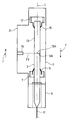
- a continuous fiberizing process of preforms for the manufacturing of an optical fiber is implemented, single figure, using a preform descent machine 1 to move in translation along a fiber-drawing axis L a first preform 3 fixed in a mandrel 5 secured to a first movable carriage 7 following the fiber axis.
- the first preform 3 is lowered by the first carriage 7 through a fiber-drawing oven 9 arranged in the fiber-drawing axis L to be heated and drawn into an optical fiber 11 received by a take-up reel not shown.
- a second preform 13 is moved in following translation the fiber-drawing axis L using the preform descent machine 1 in being fixed by a mandrel 15 secured to a second carriage 17 mobile along the fiber-drawing axis.
- the movement of the two carriages 7 and 17 in the direction of fibering indicated by the arrow f in the figure, is carried out at the same translation speed V.
- the installation of the second preform 13 in the preform lowering machine 1 and the tightening of the mandrel 15 of the second carriage 17 are made in such a way that the two preforms 3 and 13 are first separated from each other then arranged end to end, the contact faces being carefully polished.
- the second preform 13 is welded end to end to the first preform 3 and is moved in translation along the fiber drawing axis by the second carriage 17 to be heated in the fiber-drawing oven and stretched in optical fiber following the first preform.
- the mandrel 5 of the first carriage 7 is open to allow it to be offset from the axis of fiberizing L and being moved by the preform descent machine 1 in the opposite direction to the fiber drawing indicated by the arrow r in the figure.
- This first carriage is replaced in the fiber-drawing axis occupying the initial position of the second carriage 17 to allow setting place of a third preform placed end to end with the second preform and thus ensure continuous fiberizing of preforms.
- the butt welding of the two preforms 3 and 13 is produced by moving a power laser 19 along the axis of fiberizing L and by controlling its displacement to that of the two preforms to maintain a laser beam at the same height as the two ends 3A and 13A to be welded.
- a power laser 19 is guided in displacement parallel to the fiber drawing axis L by a guide rod 21 integral of the preform descent machine 1.
- the power laser 19 is moved in the fiber-drawing direction f using a conventional mechanism, and is slaved to the movement of the two preforms along the preform lowering machine 1 for maintaining a laser beam 23 at the same height as the two ends 3A and 13A of the preforms at solder. Controlling the movement of the power laser 19 moving the two preforms reduces the area affected by welding.
- the energy provided by the laser is focused on the two ends 3A and 13A of the preforms to be welded so that the lateral surface of the two preforms, upstream and downstream of the weld zone, is not exposed to the beam and is therefore not polluted.
- the laser of power 19 is switched off and moved by the classic mechanism previous in the opposite direction to fiber drawing, for example so simultaneous with the first carriage 7, to occupy a position initial at the same height as the two ends in contact with the second preform and the third preform installed in the preform lowering machine to replace the first preform.
- three power lasers are arranged in a plane perpendicular to the fiber axis by being distributed around this fiber axis at 120 degrees from each other. They move together parallel to the fiber-drawing axis and their movement is controlled by that of the two preforms to maintain three laser beams at the same height as the two ends in contact of the two preforms to be welded.
- the fusion of the two ends to be welded is achieved quickly and in a way homogeneous in the weld plane.
- the power laser is moved in alternating rotation around the axis fiberizing L at the same time as it is moved in translation parallel to this fiber axis.
- a flat support is arranged perpendicular to the axis of fiber drawing and is guided in translation parallel to the fiber drawing axis by a guide rod, a central opening allowing passage preforms through this planar support.
- the power laser is rotatably mounted on the planar support by describing a circle around the fiber-drawing axis, the laser beam being directed on the two ends of the two preforms to solder.
- the translational movement of the planar support is subject to displacement of the two preforms so that the laser beam is kept at the same height as the two ends of the preforms at solder.
- the rotational movement of the power laser is chosen in function of a number of alternating turns sufficient to carry the two fusion ends and weld the two preforms during their lowering by the preform lowering machine.
- the heat necessary for the fusion of the two ends in contact of the two preforms is brought continuously to the periphery of the two tips which allow a fast and homogeneous fusion with a single laser power.
Abstract
Description
L'invention se rapporte à un procédé de fibrage en continu de préformes pour la fabrication d'une fibre optique, dans lequel on déplace suivant un axe de fibrage une première préforme que l'on étire en fibre optique à travers un four de fibrage disposé dans l'axe de fibrage, et l'on déplace suivant l'axe de fibrage une deuxième préforme que l'on soude bout à bout avec la première préforme pour être étirée en fibre optique à la suite de la première préforme.The invention relates to a continuous fiber drawing process for preforms for the manufacture of an optical fiber, in which moves along a fiberizing axis a first preform which is fiber optic stretching through a fiber-drawing oven arranged in the axis fiberizing, and we move along the fiberizing axis a second preform which is welded end to end with the first preform to be stretched in optical fiber following the first preform.
Un procédé de ce type est connu notamment de la demande de brevet US 4 407 667 publiée le 4 octobre 1983 sous revendication d'une demande FR 80 17005 déposée le 31 juillet 1980. Les préformes se présentent sous la forme de tiges de coeur destinées à être rechargées au cours de leur déplacement suivant l'axe de fibrage avant d'être étirées en fibre optique. La soudure bout à bout des deux tiges de coeur est réalisée dans une station de soudage qui est fixe par rapport à l'axe de fibrage et qui comprend un four ou une torche annulaire comme source de chaleur nécessaire à la soudure par fusion des deux bouts des préformes en contact l'une avec l'autre. Les deux tiges de coeur sont entraínées en déplacement suivant l'axe de fibrage par des rouleaux à une même vitesse de l'ordre de 8 millimètres par minute.A process of this type is known in particular from the application for US Patent 4,407,667 published on October 4, 1983 under claim of an application FR 80 17005 filed on July 31, 1980. The preforms are in the form of heart stems intended for be recharged during their movement along the fiber axis before being stretched into optical fiber. Butt welding of the two core rods is made in a soldering station which is fixed with respect to the fiber-drawing axis and which comprises an oven or a torch annular as a heat source necessary for welding by fusion of the two ends of the preforms in contact with each other. The two heart rods are driven in displacement along the axis of fibering by rollers at the same speed of the order of 8 millimeters per minute.
Le procédé décrit dans la demande précédente se révèle non dépourvu d'inconvénients.The process described in the previous request turns out not devoid of disadvantages.
D'une part, le déplacement des deux préformes à une certaine vitesse à travers la station de soudage fixe est responsable d'un échauffement des préformes en amont et en aval des deux bouts à souder. Cet excédent de chaleur se propage dans la direction axiale des préformes et contribue encore à étendre la zone affectée par la soudure. Lors de l'étirage des préformes, cette zone donne naissance à une fibre optique qui présente souvent des paramètres d'atténuation dégradés et doit être soustraite de la production du procédé de fibrage.On the one hand, the displacement of the two preforms to a certain speed through the stationary soldering station is responsible for a heating of the preforms upstream and downstream of the two ends at solder. This excess heat propagates in the axial direction preforms and further helps to expand the area affected by the welding. When stretching the preforms, this area gives birth to an optical fiber which often has attenuation parameters degraded and must be subtracted from the production of the process of fiberizing.
D'autre part, l'utilisation d'un four ou d'une torche annulaire en tant que source de chaleur pose un problème de pollution de la surface latérale des préformes lors de leur passage à travers la station de soudage.On the other hand, the use of an oven or an annular torch in as a heat source poses a pollution problem of the lateral surface of the preforms as they pass through the soldering station.
Le but de l'invention est un procédé de fibrage qui pallie les inconvénients décrits précédemment.The object of the invention is a fiberizing process which overcomes the disadvantages described above.
L'idée à la base de l'invention est de souder les deux préformes en utilisant une source de chaleur non polluante et qui se déplace suivant l'axe de fibrage.The idea behind the invention is to weld the two preforms using a non-polluting and moving heat source along the fiber axis.
A cet effet, l'invention a pour objet un procédé de fibrage en continu de préformes pour la fabrication d'une fibre optique, dans lequel on déplace suivant un axe de fibrage une première préforme que l'on étire en fibre optique à travers un four de fibrage disposé dans l'axe de fibrage, et l'on déplace suivant l'axe de fibrage une deuxième préforme que l'on soude bout à bout avec la première préforme pour être étirée en fibre optique à la suite de la première préforme, caractérisé en ce que la soudure bout à bout des deux préformes est réalisée en déplaçant un laser de puissance suivant l'axe de fibrage et en asservissant son déplacement à celui des deux préformes pour maintenir un faisceau laser émis par le laser de puissance, à une même hauteur que les deux bouts à souder.To this end, the invention relates to a fiber-drawing process in continuous preforms for the manufacture of an optical fiber, in which one moves along a fiberizing axis a first preform which is stretched in optical fiber through a fiber-drawing oven arranged in the fiberizing axis, and one moves along the fiberizing axis a second preform which is welded end to end with the first preform to be stretched in optical fiber after the first preform, characterized in that the butt welding of the two preforms is achieved by moving a next power laser the fiber-drawing axis and by controlling its displacement to that of the two preforms to maintain a laser beam emitted by the laser of power, at the same height as the two ends to be welded.
En déplaçant le laser de puissance suivant l'axe de fibrage et en asservissant son déplacement à celui des deux préformes pour maintenir un faisceau laser à une même hauteur que les deux bouts à souder, on réduit considérablement la zone affectée par la soudure.By moving the power laser along the fiber axis and slaving its movement to that of the two preforms for maintain a laser beam at the same height as the two ends at welding, the area affected by the welding is considerably reduced.
Le faisceau laser est maintenu à la même hauteur que les deux bouts des préformes à souder de telle sorte que, en amont et en aval de la zone de soudure, la surface latérale des deux préformes n'est pas exposée au laser, et par conséquent n'est pas polluée.The laser beam is kept at the same height as the two ends of the preforms to be welded so that upstream and downstream of the weld zone, the lateral surface of the two preforms is not not exposed to the laser, and therefore is not polluted.
D'autres caractéristiques et avantages de l'invention apparaítront à la lecture de la description d'un mode de réalisation de l'invention illustré par la figure unique qui montre de façon schématique une unité de fibrage permettant la mise en oeuvre d'un procédé selon l'invention.Other characteristics and advantages of the invention will appear on reading the description of an embodiment of the invention illustrated by the single figure which schematically shows a fiberizing unit allowing the implementation of a method according to the invention.
Un procédé de fibrage en continu de préformes pour la
fabrication d'une fibre optique est mis en oeuvre, figure unique, à
l'aide d'une machine de descente préforme 1 pour déplacer en
translation suivant un axe de fibrage L une première préforme 3 fixée
dans un mandrin 5 solidaire d'un premier chariot 7 mobile suivant
l'axe de fibrage. La première préforme 3 est descendue par le premier
chariot 7 à travers un four de fibrage 9 disposé dans l'axe de fibrage L
pour être chauffée et étirée en une fibre optique 11 reçue par une
bobine réceptrice non représentée.A continuous fiberizing process of preforms for the
manufacturing of an optical fiber is implemented, single figure,
using a
Une deuxième préforme 13 est déplacée en translation suivant
l'axe de fibrage L à l'aide de la machine de descente préforme 1 en
étant fixée par un mandrin 15 solidaire d'un deuxième chariot 17
mobile suivant l'axe de fibrage.A
Le déplacement des deux chariots 7 et 17 dans le sens du
fibrage indiqué par la flèche f sur la figure, s'effectue à une même
vitesse de translation V. La mise en place de la deuxième préforme 13
dans la machine de descente préforme 1 et le serrage du mandrin 15
du deuxième chariot 17 sont réalisés de façon telle à ce que les deux
préformes 3 et 13 soient d'abord séparées l'une de l'autre puis
disposées bout à bout, les faces de contact étant soigneusement
polies.The movement of the two
La deuxième préforme 13 est soudée bout à bout à la première
préforme 3 et est déplacée en translation suivant l'axe de fibrage par
le deuxième chariot 17 pour être chauffée dans le four de fibrage et
étirée en fibre optique à la suite de la première préforme. A la fin du
fibrage de la première préforme 3, le mandrin 5 du premier chariot 7
est ouvert pour permettre à celui-ci d'être décalé par rapport à l'axe de
fibrage L et d'être déplacé par la machine de descente préforme 1
dans le sens opposé au fibrage indiqué par la flèche r sur la figure. Ce
premier chariot est replacé dans l'axe de fibrage en occupant la
position initiale du deuxième chariot 17 pour permettre la mise en
place d'une troisième préforme disposée bout à bout avec la
deuxième préforme et assurer ainsi un fibrage en continu des
préformes.The
Selon l'invention, la soudure bout à bout des deux préformes 3 et
13 est réalisée en déplaçant un laser de puissance 19 suivant l'axe de
fibrage L et en asservissant son déplacement à celui des deux
préformes pour maintenir un faisceau laser à une même hauteur que
les deux bouts 3A et 13A à souder.According to the invention, the butt welding of the two
Sur la figure, un laser de puissance 19 est guidé en déplacement
parallèlement à l'axe de fibrage L par une tige de guidage 21 solidaire
de la machine de descente préforme 1. Le laser de puissance 19 est
déplacé dans le sens de fibrage f à l'aide d'un mécanisme classique,
et est asservi au déplacement des deux préformes le long de la
machine de descente préforme 1 pour maintenir un faisceau laser 23
à une même hauteur que les deux bouts 3A et 13A des préformes à
souder. L'asservissement du déplacement du laser de puissance 19
au déplacement des deux préformes permet de réduire la zone
affectée par la soudure. L'énergie apportée par le laser est focalisée
sur les deux bouts 3A et 13A des préformes à souder de telle sorte
que la surface latérale des deux préformes, en amont et en aval de la
zone de soudure, n'est pas exposée au faisceau et n'est donc pas
polluée. In the figure, a
A la fin du fibrage de la première préforme 3, le laser de
puissance 19 est éteint et déplacé par le mécanisme classique
précédent dans le sens r opposé au fibrage, par exemple de façon
simultanée avec le premier chariot 7, pour occuper une position
initiale à une même hauteur que les deux bouts en contact de la
deuxième préforme et de la troisième préforme installée dans la
machine de descente préforme en remplacement de la première
préforme.At the end of the fiberizing of the
Dans une première variante de réalisation de l'invention, trois lasers de puissances sont disposés dans un plan perpendiculaire à l'axe de fibrage en étant distribués autour de cet axe de fibrage à 120 degrés les uns des autres. Ils se déplacent ensemble parallèlement à l'axe de fibrage et leur déplacement est asservi à celui des deux préformes pour maintenir trois faisceaux laser à la même hauteur que les deux bouts en contact des deux préformes à souder.In a first variant of the invention, three power lasers are arranged in a plane perpendicular to the fiber axis by being distributed around this fiber axis at 120 degrees from each other. They move together parallel to the fiber-drawing axis and their movement is controlled by that of the two preforms to maintain three laser beams at the same height as the two ends in contact of the two preforms to be welded.
Selon cette première variante de réalisation de l'invention, la fusion des deux bouts à souder est atteinte rapidement et d'une façon homogène dans le plan de soudure.According to this first alternative embodiment of the invention, the fusion of the two ends to be welded is achieved quickly and in a way homogeneous in the weld plane.
Dans une deuxième variante de réalisation de l'invention, le laser de puissance est déplacé en rotation altemative autour de l'axe de fibrage L en même temps qu'il est déplacé en translation parallèlement à cet axe de fibrage.In a second variant embodiment of the invention, the power laser is moved in alternating rotation around the axis fiberizing L at the same time as it is moved in translation parallel to this fiber axis.
Un support plan est disposé perpendiculairement à l'axe de fibrage et est guidé en translation parallèlement à l'axe de fibrage par une tige de guidage, une ouverture centrale permettant le passage des préformes à travers ce support plan.A flat support is arranged perpendicular to the axis of fiber drawing and is guided in translation parallel to the fiber drawing axis by a guide rod, a central opening allowing passage preforms through this planar support.
Le laser de puissance est monté mobile en rotation sur le support plan en décrivant un cercle autour de l'axe de fibrage, le faisceau laser étant dirigé sur les deux bouts des deux préformes à souder. The power laser is rotatably mounted on the planar support by describing a circle around the fiber-drawing axis, the laser beam being directed on the two ends of the two preforms to solder.
Le déplacement en translation du support plan est asservi au déplacement des deux préformes pour que le faisceau laser soit maintenu à une même hauteur que les deux bouts des préformes à souder.The translational movement of the planar support is subject to displacement of the two preforms so that the laser beam is kept at the same height as the two ends of the preforms at solder.
Le déplacement en rotation du laser de puissance est choisi en fonction d'un nombre de tours alternatifs suffisants pour porter les deux bouts à fusion et souder les deux préformes pendant leur descente par la machine de descente préforme.The rotational movement of the power laser is chosen in function of a number of alternating turns sufficient to carry the two fusion ends and weld the two preforms during their lowering by the preform lowering machine.
Selon cette deuxième variante de réalisation de l'invention, la chaleur nécessaire à la fusion des deux bouts en contact des deux préformes est apportée de façon continue à la périphérie des deux bouts ce qui permet une fusion rapide et homogène avec un seul laser de puissance.According to this second variant embodiment of the invention, the heat necessary for the fusion of the two ends in contact of the two preforms is brought continuously to the periphery of the two tips which allow a fast and homogeneous fusion with a single laser power.
Claims (3)
Applications Claiming Priority (2)
| Application Number | Priority Date | Filing Date | Title |
|---|---|---|---|
| FR9801336A FR2774372B1 (en) | 1998-02-05 | 1998-02-05 | CONTINUOUS FIBRATION PROCESS OF PREFORMS FOR THE MANUFACTURE OF OPTICAL FIBERS |
| FR9801336 | 1998-02-05 |
Publications (2)
| Publication Number | Publication Date |
|---|---|
| EP0934909A1 true EP0934909A1 (en) | 1999-08-11 |
| EP0934909B1 EP0934909B1 (en) | 2001-04-25 |
Family
ID=9522621
Family Applications (1)
| Application Number | Title | Priority Date | Filing Date |
|---|---|---|---|
| EP99400214A Expired - Lifetime EP0934909B1 (en) | 1998-02-05 | 1999-02-01 | Process for continuous drawing of preforms for manufacturing optical fibres |
Country Status (9)
| Country | Link |
|---|---|
| US (1) | US6098429A (en) |
| EP (1) | EP0934909B1 (en) |
| JP (1) | JPH11292560A (en) |
| KR (1) | KR19990072430A (en) |
| CN (1) | CN1147441C (en) |
| BR (1) | BR9900535A (en) |
| DE (1) | DE69900086T2 (en) |
| DK (1) | DK0934909T3 (en) |
| FR (1) | FR2774372B1 (en) |
Families Citing this family (20)
| Publication number | Priority date | Publication date | Assignee | Title |
|---|---|---|---|---|
| DE19963867C1 (en) * | 1999-12-30 | 2001-06-13 | Schott Glas | Apparatus for re-melting glass rods e.g., semi-finished products comprises a sleeve, a crucible located below the sleeve and having a run-off, a heater for heating the inside of the crucible and a run-off sleeve connected to the crucible |
| WO2001064591A1 (en) * | 2000-03-01 | 2001-09-07 | Heraeus Amersil, Inc. | Method, apparatus, and article of manufacture for determining an amount of energy needed to bring a quartz workpiece to a fusion weldable condition |
| KR100505940B1 (en) * | 2001-03-21 | 2005-08-05 | 광주과학기술원 | Method and apparatus for drawing a plastic optical fiber by using a preform |
| US20030081906A1 (en) * | 2001-10-26 | 2003-05-01 | Filhaber John F. | Direct bonding of optical components |
| US20030079503A1 (en) * | 2001-10-26 | 2003-05-01 | Cook Glen B. | Direct bonding of glass articles for drawing |
| US20030164006A1 (en) * | 2001-10-26 | 2003-09-04 | Buchanan Karl H. | Direct bonding of glass articles for drawing |
| US6836602B2 (en) | 2001-10-26 | 2004-12-28 | Corning Incorporated | Direct bonding of optical components |
| US20030188553A1 (en) * | 2002-04-08 | 2003-10-09 | Mann Larry G. | Direct bonding methods using lithium |
| US6791748B2 (en) | 2002-05-02 | 2004-09-14 | Corning Incorporated | Optical isolators and methods of manufacture |
| US6950235B2 (en) * | 2002-05-02 | 2005-09-27 | Corning Incorporated | Optical isolators and methods of manufacture |
| US20030230113A1 (en) * | 2002-06-12 | 2003-12-18 | Patrick Gedeon | Methods for manufacturing glass articles |
| US20040187525A1 (en) * | 2003-03-31 | 2004-09-30 | Coffey Calvin T. | Method and apparatus for making soot |
| US20050223748A1 (en) * | 2004-03-30 | 2005-10-13 | Ames Donald J | Method of joining optical fiber preforms and apparatus therefor |
| ATE430327T1 (en) * | 2004-05-24 | 2009-05-15 | Prysmian Spa | PROCESS AND APPARATUS FOR PRODUCING AN OPTICAL CABLE |
| JP2007039260A (en) * | 2005-08-01 | 2007-02-15 | Canon Inc | Method for manufacturing drawn glass member, method for manufacturing spacer, and method for manufacturing image display device |
| DE102005044947B4 (en) * | 2005-09-20 | 2007-10-04 | Heraeus Tenevo Gmbh | Welding method for joining components made of high-siliceous material, as well as apparatus for carrying out the method |
| DE102006033603B3 (en) * | 2006-07-18 | 2007-07-05 | Heraeus Tenevo Gmbh | Optical component manufacturing method, involves indirectly or directly attaching distal end of hollow cylinder to proximal end of another hollow cylinder before complete collapsing of annular gap |
| FR2914297B1 (en) * | 2007-03-27 | 2009-05-08 | Draka Comteq France | PROCESS FOR PRODUCING AN OPTICAL FIBER PREFORM |
| KR101955132B1 (en) * | 2014-08-13 | 2019-03-06 | 헤래우스 테네보 엘엘씨 | Quartz glass article and method for forming a quartz glass optical component |
| CN108585469B (en) * | 2018-07-26 | 2021-02-12 | 杭州富通通信技术股份有限公司 | Method for producing optical fiber |
Citations (3)
| Publication number | Priority date | Publication date | Assignee | Title |
|---|---|---|---|---|
| DE2932196A1 (en) * | 1979-08-08 | 1981-02-26 | Siemens Ag | Long optical waveguide fibres - made by drawing very long blank obtd. by butt welding several short blanks together |
| GB2081250A (en) * | 1980-07-31 | 1982-02-17 | Boscher Daniel | Method and apparatus for fabricating optical fibres |
| JPH09202639A (en) * | 1995-11-20 | 1997-08-05 | Kobe Steel Ltd | Device for continuously transferring optical fiber base material |
Family Cites Families (3)
| Publication number | Priority date | Publication date | Assignee | Title |
|---|---|---|---|---|
| DE151925C (en) * | ||||
| US3114621A (en) * | 1957-04-09 | 1963-12-17 | Kiraly Tibor | Apparatus for cutting off lengths of glass tubing |
| US3384567A (en) * | 1965-10-22 | 1968-05-21 | Gen Electric | Electrolyte guide member |
-
1998
- 1998-02-05 FR FR9801336A patent/FR2774372B1/en not_active Expired - Fee Related
-
1999
- 1999-02-01 DK DK99400214T patent/DK0934909T3/en active
- 1999-02-01 EP EP99400214A patent/EP0934909B1/en not_active Expired - Lifetime
- 1999-02-01 DE DE69900086T patent/DE69900086T2/en not_active Expired - Fee Related
- 1999-02-04 BR BR9900535-2A patent/BR9900535A/en not_active Application Discontinuation
- 1999-02-04 JP JP11027898A patent/JPH11292560A/en active Pending
- 1999-02-04 KR KR1019990003834A patent/KR19990072430A/en not_active Application Discontinuation
- 1999-02-04 US US09/244,625 patent/US6098429A/en not_active Expired - Fee Related
- 1999-02-04 CN CNB991029917A patent/CN1147441C/en not_active Expired - Fee Related
Patent Citations (3)
| Publication number | Priority date | Publication date | Assignee | Title |
|---|---|---|---|---|
| DE2932196A1 (en) * | 1979-08-08 | 1981-02-26 | Siemens Ag | Long optical waveguide fibres - made by drawing very long blank obtd. by butt welding several short blanks together |
| GB2081250A (en) * | 1980-07-31 | 1982-02-17 | Boscher Daniel | Method and apparatus for fabricating optical fibres |
| JPH09202639A (en) * | 1995-11-20 | 1997-08-05 | Kobe Steel Ltd | Device for continuously transferring optical fiber base material |
Non-Patent Citations (1)
| Title |
|---|
| PATENT ABSTRACTS OF JAPAN vol. 97, no. 12 25 December 1997 (1997-12-25) * |
Also Published As
| Publication number | Publication date |
|---|---|
| KR19990072430A (en) | 1999-09-27 |
| EP0934909B1 (en) | 2001-04-25 |
| CN1147441C (en) | 2004-04-28 |
| US6098429A (en) | 2000-08-08 |
| DE69900086T2 (en) | 2001-11-15 |
| CN1241541A (en) | 2000-01-19 |
| DE69900086D1 (en) | 2001-05-31 |
| FR2774372A1 (en) | 1999-08-06 |
| BR9900535A (en) | 2000-04-25 |
| JPH11292560A (en) | 1999-10-26 |
| DK0934909T3 (en) | 2001-08-13 |
| FR2774372B1 (en) | 2000-03-03 |
Similar Documents
| Publication | Publication Date | Title |
|---|---|---|
| EP0934909B1 (en) | Process for continuous drawing of preforms for manufacturing optical fibres | |
| EP0950643B1 (en) | Soldering the ends of optical preforms together by means of a plasma torch | |
| JPH0444242B2 (en) | ||
| US4969255A (en) | Apparatus for producing heat exchanger tubes | |
| TW201805100A (en) | Laser processing apparatus and method | |
| NL9202128A (en) | METHOD AND APPARATUS FOR WELDING WORKPIECES FROM SUPER ALLOYS | |
| LU80792A1 (en) | DISPSITIVE AND METHOD FOR PERFORMING PERFORATIONS ON THE SURFACE OF ROLLING MILLS | |
| KR920018501A (en) | Symmetric fusion splicing and flame polishing apparatus and method thereof | |
| EP0025585A1 (en) | Method and apparatus for welding optical fibres | |
| FR2647042A1 (en) | BEAM GUIDING DEVICE FOR MACHINING LASER PARTS | |
| JPH05115993A (en) | Laser beam machine | |
| EP1960148B1 (en) | Automatic welding device of the mig/mag type | |
| EP0599737B1 (en) | Build-up procedure on a work piece by plasma with transferred arc | |
| EP1065174B1 (en) | Plasma burner, method for making an optical preform and apparatus used therefor | |
| EP0928780B1 (en) | Apparatus for butt-welding optical fibre preforms | |
| FR2884741A1 (en) | METHOD FOR WELDING PIPELINE TYPE METAL PIPING AND ITS IMPLEMENTATION DEVICE | |
| EP0593337B1 (en) | Apparatus for the fabrication of thermoplastic filament windings | |
| US20230278139A1 (en) | Welding method and laser device | |
| FR2587502A1 (en) | Apparatus enabling optical fibres to be melted and drawn, especially for the manufacture of couplers | |
| FR2812227A1 (en) | Laser welding of a pipeline, uses multiple laser beams delivered through optic fibers to focussing head, supplied by generator and source unit running alongside pipe | |
| EP0922519B1 (en) | Method of cutting by geometrically and thermally and/or mechanically deforming a saw wire or saw blade, and sawing machine | |
| EP1249301A1 (en) | Device and associated process of so called laser welding bi-layer | |
| BE827882A (en) | APPARATUS FOR LASER WELDING OF A PIPOLINE | |
| SU1536645A1 (en) | Laser welding apparatus | |
| FR2742370A1 (en) | METAL STRIP SPLICE PROCESS AND MACHINE FOR ITS IMPLEMENTATION |
Legal Events
| Date | Code | Title | Description |
|---|---|---|---|
| PUAI | Public reference made under article 153(3) epc to a published international application that has entered the european phase |
Free format text: ORIGINAL CODE: 0009012 |
|
| AK | Designated contracting states |
Kind code of ref document: A1 Designated state(s): DE DK FI GB IT NL SE |
|
| AX | Request for extension of the european patent |
Free format text: AL;LT;LV;MK;RO;SI |
|
| 17P | Request for examination filed |
Effective date: 20000211 |
|
| AKX | Designation fees paid |
Free format text: DE DK FI GB IT NL SE |
|
| GRAG | Despatch of communication of intention to grant |
Free format text: ORIGINAL CODE: EPIDOS AGRA |
|
| 17Q | First examination report despatched |
Effective date: 20000523 |
|
| GRAG | Despatch of communication of intention to grant |
Free format text: ORIGINAL CODE: EPIDOS AGRA |
|
| GRAH | Despatch of communication of intention to grant a patent |
Free format text: ORIGINAL CODE: EPIDOS IGRA |
|
| GRAH | Despatch of communication of intention to grant a patent |
Free format text: ORIGINAL CODE: EPIDOS IGRA |
|
| GRAA | (expected) grant |
Free format text: ORIGINAL CODE: 0009210 |
|
| AK | Designated contracting states |
Kind code of ref document: B1 Designated state(s): DE DK FI GB IT NL SE |
|
| PG25 | Lapsed in a contracting state [announced via postgrant information from national office to epo] |
Ref country code: FI Free format text: LAPSE BECAUSE OF FAILURE TO SUBMIT A TRANSLATION OF THE DESCRIPTION OR TO PAY THE FEE WITHIN THE PRESCRIBED TIME-LIMIT Effective date: 20010425 |
|
| ITF | It: translation for a ep patent filed |
Owner name: JACOBACCI & PERANI S.P.A. |
|
| GBT | Gb: translation of ep patent filed (gb section 77(6)(a)/1977) |
Effective date: 20010427 |
|
| REF | Corresponds to: |
Ref document number: 69900086 Country of ref document: DE Date of ref document: 20010531 |
|
| PG25 | Lapsed in a contracting state [announced via postgrant information from national office to epo] |
Ref country code: SE Free format text: LAPSE BECAUSE OF FAILURE TO SUBMIT A TRANSLATION OF THE DESCRIPTION OR TO PAY THE FEE WITHIN THE PRESCRIBED TIME-LIMIT Effective date: 20010725 |
|
| REG | Reference to a national code |
Ref country code: DK Ref legal event code: T3 |
|
| REG | Reference to a national code |
Ref country code: GB Ref legal event code: IF02 |
|
| PG25 | Lapsed in a contracting state [announced via postgrant information from national office to epo] |
Ref country code: DK Free format text: LAPSE BECAUSE OF NON-PAYMENT OF DUE FEES Effective date: 20020228 |
|
| PLBE | No opposition filed within time limit |
Free format text: ORIGINAL CODE: 0009261 |
|
| STAA | Information on the status of an ep patent application or granted ep patent |
Free format text: STATUS: NO OPPOSITION FILED WITHIN TIME LIMIT |
|
| 26N | No opposition filed | ||
| REG | Reference to a national code |
Ref country code: DK Ref legal event code: EBP |
|
| PG25 | Lapsed in a contracting state [announced via postgrant information from national office to epo] |
Ref country code: NL Free format text: LAPSE BECAUSE OF NON-PAYMENT OF DUE FEES Effective date: 20030901 |
|
| NLV4 | Nl: lapsed or anulled due to non-payment of the annual fee |
Effective date: 20030901 |
|
| PGFP | Annual fee paid to national office [announced via postgrant information from national office to epo] |
Ref country code: GB Payment date: 20070216 Year of fee payment: 9 Ref country code: DE Payment date: 20070216 Year of fee payment: 9 |
|
| PGFP | Annual fee paid to national office [announced via postgrant information from national office to epo] |
Ref country code: IT Payment date: 20070622 Year of fee payment: 9 |
|
| GBPC | Gb: european patent ceased through non-payment of renewal fee |
Effective date: 20080201 |
|
| PG25 | Lapsed in a contracting state [announced via postgrant information from national office to epo] |
Ref country code: DE Free format text: LAPSE BECAUSE OF NON-PAYMENT OF DUE FEES Effective date: 20080902 |
|
| PG25 | Lapsed in a contracting state [announced via postgrant information from national office to epo] |
Ref country code: GB Free format text: LAPSE BECAUSE OF NON-PAYMENT OF DUE FEES Effective date: 20080201 |
|
| PG25 | Lapsed in a contracting state [announced via postgrant information from national office to epo] |
Ref country code: IT Free format text: LAPSE BECAUSE OF NON-PAYMENT OF DUE FEES Effective date: 20080201 |