EP0934874B1 - Aircraft undercarriage door latching assembly - Google Patents
Aircraft undercarriage door latching assembly Download PDFInfo
- Publication number
- EP0934874B1 EP0934874B1 EP99102097A EP99102097A EP0934874B1 EP 0934874 B1 EP0934874 B1 EP 0934874B1 EP 99102097 A EP99102097 A EP 99102097A EP 99102097 A EP99102097 A EP 99102097A EP 0934874 B1 EP0934874 B1 EP 0934874B1
- Authority
- EP
- European Patent Office
- Prior art keywords
- piston
- fluid
- actuating means
- catch member
- assembly
- Prior art date
- Legal status (The legal status is an assumption and is not a legal conclusion. Google has not performed a legal analysis and makes no representation as to the accuracy of the status listed.)
- Expired - Lifetime
Links
Images

Classifications
-
- B—PERFORMING OPERATIONS; TRANSPORTING
- B64—AIRCRAFT; AVIATION; COSMONAUTICS
- B64C—AEROPLANES; HELICOPTERS
- B64C25/00—Alighting gear
- B64C25/02—Undercarriages
- B64C25/08—Undercarriages non-fixed, e.g. jettisonable
- B64C25/10—Undercarriages non-fixed, e.g. jettisonable retractable, foldable, or the like
- B64C25/18—Operating mechanisms
- B64C25/26—Control or locking systems therefor
-
- Y—GENERAL TAGGING OF NEW TECHNOLOGICAL DEVELOPMENTS; GENERAL TAGGING OF CROSS-SECTIONAL TECHNOLOGIES SPANNING OVER SEVERAL SECTIONS OF THE IPC; TECHNICAL SUBJECTS COVERED BY FORMER USPC CROSS-REFERENCE ART COLLECTIONS [XRACs] AND DIGESTS
- Y10—TECHNICAL SUBJECTS COVERED BY FORMER USPC
- Y10S—TECHNICAL SUBJECTS COVERED BY FORMER USPC CROSS-REFERENCE ART COLLECTIONS [XRACs] AND DIGESTS
- Y10S292/00—Closure fasteners
- Y10S292/12—Closure operators
-
- Y—GENERAL TAGGING OF NEW TECHNOLOGICAL DEVELOPMENTS; GENERAL TAGGING OF CROSS-SECTIONAL TECHNOLOGIES SPANNING OVER SEVERAL SECTIONS OF THE IPC; TECHNICAL SUBJECTS COVERED BY FORMER USPC CROSS-REFERENCE ART COLLECTIONS [XRACs] AND DIGESTS
- Y10—TECHNICAL SUBJECTS COVERED BY FORMER USPC
- Y10S—TECHNICAL SUBJECTS COVERED BY FORMER USPC CROSS-REFERENCE ART COLLECTIONS [XRACs] AND DIGESTS
- Y10S292/00—Closure fasteners
- Y10S292/13—Cow proof latches
-
- Y—GENERAL TAGGING OF NEW TECHNOLOGICAL DEVELOPMENTS; GENERAL TAGGING OF CROSS-SECTIONAL TECHNOLOGIES SPANNING OVER SEVERAL SECTIONS OF THE IPC; TECHNICAL SUBJECTS COVERED BY FORMER USPC CROSS-REFERENCE ART COLLECTIONS [XRACs] AND DIGESTS
- Y10—TECHNICAL SUBJECTS COVERED BY FORMER USPC
- Y10T—TECHNICAL SUBJECTS COVERED BY FORMER US CLASSIFICATION
- Y10T292/00—Closure fasteners
- Y10T292/08—Bolts
- Y10T292/087—Loops
- Y10T292/0874—Spring-arm catch
-
- Y—GENERAL TAGGING OF NEW TECHNOLOGICAL DEVELOPMENTS; GENERAL TAGGING OF CROSS-SECTIONAL TECHNOLOGIES SPANNING OVER SEVERAL SECTIONS OF THE IPC; TECHNICAL SUBJECTS COVERED BY FORMER USPC CROSS-REFERENCE ART COLLECTIONS [XRACs] AND DIGESTS
- Y10—TECHNICAL SUBJECTS COVERED BY FORMER USPC
- Y10T—TECHNICAL SUBJECTS COVERED BY FORMER US CLASSIFICATION
- Y10T292/00—Closure fasteners
- Y10T292/08—Bolts
- Y10T292/0894—Spring arm
Definitions
- This invention relates to an assembly for retaining a catch member in a first condition and for releasing the catch member when desired for movement to a second condition. More particularly but not exclusively the invention has been designed for application as a so called uplock assembly for the latching and unlatching of a door assembly associated with the deployment and stowing of an undercarriage of an aircraft, although the invention may otherwise be applied for example to an uplock assembly for the retention and release of an undercarriage of an aircraft.
- a door covering an undercarriage well is opened to permit the undercarriage to be deployed.
- the door is usually open (although on some types of aircraft the undercarriage well doors are closed when the undercarriage is deployed) and an uplock assembly thereof unlatched.
- a usually hydraulic actuator is operated to close the undercarriage well door until a catch member of the door co-operates with a latch of an uplock assembly to prevent the unintentional opening of the door during flight.
- the uplock assembly needs to be released to permit the door to open by e.g. hydraulically aided means and/or with the aid of gravity, and the undercarriage to be lowered.
- Known uplock assemblies are generally of a complex construction requiring complex components comprising springs, cams and levers. Not only are such known assemblies unduly heavy and complex, but they are not entirely reliable. It is known for undercarriage well doors to become jammed thus preventing the undercarriage to be lowered and making landing perilous.
- Jamming can occur due to for example unfavourable operating conditions such as icy conditions.
- An assembly for retaining a catch member according to the preamble of claim 1 is known from Document GB 1499149.
- An uplock arrangement for retaining an aircraft undercarriage is disclosed in GB 2161202A but in this arrangement, in the event of icing it is necessary to utilise a mechanically operated override to release the uplock.
- an assembly for retaining a catch member in a first condition and for releasing the catch member for movement to a second condition comprising a latch member pivotable about a first pivotal axis and having a formation adapted to co-operate with the catch member to retain the catch member when the latch member is in a latched position, and a rocker member pivotable about a second pivotal axis, the latch member and the rocker member interacting to retain the latch member in its latched position, the assembly further comprising actuating means to move the rocker member about the second pivotal axis to allow the latch member to pivot about the first pivotal axis to an unlatched position to release the catch member, characterised in that the latch member and the rocker member are interconnected by a resilient biasing means, the resilient biasing means including first and second relatively movable parts with a spring acting between them and a stop means which locks the first and second relatively movable parts upon operation of the actuating means resulting in
- a lighter, less complex and therefore more reliable assembly particularly but not exclusively suited for use as an uplock assembly may be provided.
- the actuating means positively moves the rocker member so that there is no reliance on gravity to achieve this.
- the resilient biasing means will move the latch member to release the catch member in response to movement of the rocker member, in the event that the latch member is frozen or otherwise unintentionally retained in its latched position, the actuating means movement can be transmitted to the latch member, via the resilient biasing means when the stop means lock, as the resilient biasing means when locked, acts as a strut, positively to move the latch member to release the catch member.
- the spring is a compression spring which is increasingly compressed until the stop means operates.
- the resilient biasing means is connected to the rocker member at one side of the second pivotal axis and the actuating means is operated at an opposite side of the first pivotal axis
- the rocker member comprising an abutment located on the same side of the second pivotal axis as the point of connection of the resilient biasing means, which abutment co-operates with a part of the latch member to prevent the latch member rotating about the first pivotal axis. beyond the latched position when the catch member is retained, and the abutment being movable when the actuating means is actuated to permit the latch member to pivot about the first pivotal axis to release the catch member.
- rocker member may act as a lever.
- the actuating means may be fluid operated, the assembly comprising main valve means operable to permit fluid to act to move the actuating means in a first direction to release the catch member for movement to the second condition and also preferably the main valve means is operable to permit fluid to act to move the actuating means in a second direction as the catch member is returned towards the first condition.
- the actuating means may be thus driveable e.g. by fluid operated means in a second direction opposite to the first direction, if desired the actuating means may be moved in the second direction by the rocker member as the catch member is moved to towards the first condition e.g. by some power operated means, such as a further actuator
- the actuating means may be carried by a piston of a piston and cylinder arrangement, fluid acting on the piston to move the piston and hence the actuating means in the first and/or second direction, and the piston carrying an operating part which is operable to operate a check valve to open the check valve as the actuating means moves in the first direction to permit fluid to flow simultaneously to a further actuator which may be operable to move the catch member from the first to the second condition wherein the catch member is released and may be operable to move the catch member from the second to the first retained condition.
- the assembly may be for retaining a catch member in a first condition and for releasing the catch member for movement to a second condition wherein the catch member comprises a part of a door assembly of an aircraft or part of an undercarriage of an aircraft.
- the assembly may be used in combination with a fluid sequencing means for operation of the assembly, the fluid sequencing means comprising a piston and cylinder arrangement, the piston carrying the actuating means, a main valve means to supply fluid to the cylinder to move the piston and hence the actuating means when the main valve means is in a first operating condition, and the piston carrying an operating part which is operable to operate a check valve to open the check valve as the actuating means moves in a first direction to permit fluid to flow simultaneously to a further actuator.
- the fluid sequencing means comprising a piston and cylinder arrangement, the piston carrying the actuating means, a main valve means to supply fluid to the cylinder to move the piston and hence the actuating means when the main valve means is in a first operating condition, and the piston carrying an operating part which is operable to operate a check valve to open the check valve as the actuating means moves in a first direction to permit fluid to flow simultaneously to a further actuator.
- a piston of the further actuator may be moved in a first direction by fluid acting on one side of the piston when the main valve means is in the first operating condition, and fluid from the one side of the piston being able to pass back past the check valve when the piston is moved in a second direction opposite to the first direction.
- the further actuator may be so called double acting so that the piston of the further actuator is moved in the second direction when fluid acts upon an opposite side of the piston to the one side when the main valve means is in a second operating condition.
- an assembly 10 is shown for retaining a catch member 11 in a first latched condition as shown in full lines in figure 1 and for releasing the catch member 11 for movement to a second unlatched condition.
- the catch member 11 comprises a part of an undercarriage well door of an aircraft, a latch member 12 of the assembly 10 being operable when in the latched position shown, to retain the door in a closed condition.
- the latch member 12 is pivotable about a first fixed pivotal axis B and has a formation 14 of generally hook configuration adapted to co-operate with the catch member 11 to retain the catch member 11 when the latch member 12 is in the latched position, and a rocker member 16 pivotable about a second fixed pivotal axis A.
- the latch member 12 and the rocker member 16 are interconnected by a resilient biasing means 18 which acts by pulling the latch member 12 and the rocker member 16 towards one another to retain the latch member 12 in its latched position and the rocker member 16 in the position shown.
- the latch member 12 is unable to rotate clockwise further as a nib part 17 thereof is abutted by an abutment part 19 carried on the rocker member 16, and anti-clockwise movement of the latch member 12 about axis B is resisted by the catch member 11.
- the resilient biasing means 18 acts between a connection point C of the rocker member 16 which is located between the second pivot axis A and the abutment part 19, and a connection point D of the latch member 12 which is located on an opposite side of the first pivot axis B to the hook formation 14.
- the abutment part 19 of the rocker member 16 comprises a roller so that as the nib part 17 and abutment part 19 of the rocker members 16 relatively move, there is no frictional resistance between them.
- the assembly 10 further comprises an actuating means 25 which may be operated to move the rocker member 16 anticlockwise about the second pivotal axis A against the force of the resilient biasing means 18.
- an actuating means 25 which may be operated to move the rocker member 16 anticlockwise about the second pivotal axis A against the force of the resilient biasing means 18.
- the resilient biasing means 18 comprises in this example, first 26 and second 27 relatively movable parts with a spring 28 acting between them.
- the first part 26 (connected at D to the latch member 12) is slideable within the second part 27 (connected at C to the rocker member 16) such that as the rocker member 16 moves away from the latch member 12, the spring 28 is increasingly compressed between the two parts 26,27.
- a stop 30 of the first part 26 will engage a shoulder 31 of the second part 27 for a purpose hereinafter explained. When the stop 30 and shoulder 31 are engaged, they provide a stop means which locks the first and second relatively movable parts 26, 27 together against further extension.
- the resilient biasing means 18 is pivotally connected to the rocker member 16 at C on an opposite side of the pivotal axis A to where the actuating means 25 operates.
- the rocker member 16 thus comprises a lever part 32 on which the actuating means 25 bears, the actuating means 25 being carried at an end of a piston 36 which is received in a cylinder 37 to which pressurised fluid, preferably hydraulic fluid may be supplied as hereinafter explained, to move the piston 36 in the cylinder 37 to act upon the lever part 32 of the rocker member 16 to move the rocker member 16 to release the catch member 11.
- Hydraulic fluid may be fed to the cylinder 37 from a main valve means 40 which is shown in figure 2, along a supply line 41 when a spool of the main valve means 40 in the position indicated at I.
- fluid pumped to the main valve means 40 will flow through the main valve means 40, along line 41 and to a port 42 of the housing 22 of the assembly 10, which inlet 42 connects with the cylinder 37 through a cavity 44 which contains a check valve 45.
- the fluid will thus act on one side S1 of the piston 36. nearly immediately in response to movement of the rocker member 16.
- the resilient biasing means 18 will act as a rigid strut positively to cause movement of the latch member 12 to release the catch member 11 before the further actuator 55 operates.
- Fluid expelled from the one side of the piston 53 will be fed along line 51 to port 50 where the fluid will act on the check valve 45 which will still be operated upon by the operating part 47 carried by the actuating means 25.
- fluid may flow past the check valve 45 to port 42 of the housing 22 from where the fluid may flow back to the main valve means 40 and hence to tank 59.
- the catch member 11 will engage an upper jaw part 65 of the latch member 12 to move the latch member 12 back to the position shown in figure 1.
- the catch member 11 may act on the latch member 12 which will cause rocker member 16 movement, which will result in the rocker member 16 urging the actuating means 25 in a second direction opposite to the first direction.
- the actuating means 25 may be moved as indicated above to move the rocker member 16 anti clockwise about axis A to release the catch member 11.
- the piston 36 carries an operating part 47 via a linkage 48, so that the operating part 47 moves with and parallel to the piston 36.
- the operating part 47 is adapted to operate on the check valve 45 in cavity 44 to move the check valve against a spring to an open position in which the fluid entering port 42 may flow past the check valve 45 into a passage 49 and to another port 50 of the housing 22 of the assembly 10. From there the fluid flows along a line 51 to one side of a piston 53 of a further actuator 55, to effect a movement of the piston 53, outwardly of its cylinder 54 as seen in the drawings.
- the piston 53 of the further actuator 55 is connected by a mechanical linkage (not shown) to the undercarriage well door having the catch member 11 so that when the catch member 11 is released, the door may be opened by the further actuator 55.
- the further actuator 55 is a so called double actuating actuator and fluid expelled from the opposite side of the piston 53 flows via a return line 58 through the main valve means 40 to a reservoir 59 from where the fluid may be drawn by a pump 60 for use, as does excess fluid from the cylinder 37 of the actuating means which flows to a port 62 in communication with line 58.
- the relative movement between the two parts 26,27 of the resilient biasing means 18 is restricted by the engagement of stop 30 and shoulder 31.
- the stop 30 and shoulder 31 engage before the operating part 47 operates on the check valve 45 so that the further actuator 55 does not commence premature movement of the catch member 11.
- piston 36 movement will move operating part 47 out of operating engagement with the check valve 45, although excess fluid fed to port 50, if of sufficient pressure, may open check valve 45 against its spring to permit excess fluid from the further activator 55 to return to tank 59 along line 41.
- latch member 12 and rocker member 16 need not be of the configurations described but alternative configurations are no doubt possible.
- the arrangement shown and described above does however provide for a greater force to be available to release the catch member 11 which is an essential safety feature where the invention is applied to operate an aircraft uplock assembly.
- the hydraulic circuit in which the assembly 10 is provided my be of an alternative configuration and may have additional components such as one way/check valves, filters and the like which are not shown or described herein or indeed need not be a hydraulic circuit as described but may be another fluid circuit.
- the circuit shown and described has been found to be virtually immune from pressure spikes which can occur in a complex aircraft system for example.
Description
- This invention relates to an assembly for retaining a catch member in a first condition and for releasing the catch member when desired for movement to a second condition. More particularly but not exclusively the invention has been designed for application as a so called uplock assembly for the latching and unlatching of a door assembly associated with the deployment and stowing of an undercarriage of an aircraft, although the invention may otherwise be applied for example to an uplock assembly for the retention and release of an undercarriage of an aircraft.
- When an aircraft is landing, a door covering an undercarriage well is opened to permit the undercarriage to be deployed. When the undercarriage is deployed, the door is usually open (although on some types of aircraft the undercarriage well doors are closed when the undercarriage is deployed) and an uplock assembly thereof unlatched. When the aircraft is flying, the undercarriage is retracted into an undercarriage well for stowage and when an indication is given that the undercarriage is fully stowed, a usually hydraulic actuator is operated to close the undercarriage well door until a catch member of the door co-operates with a latch of an uplock assembly to prevent the unintentional opening of the door during flight.
- To land, the uplock assembly needs to be released to permit the door to open by e.g. hydraulically aided means and/or with the aid of gravity, and the undercarriage to be lowered.
- Known uplock assemblies are generally of a complex construction requiring complex components comprising springs, cams and levers. Not only are such known assemblies unduly heavy and complex, but they are not entirely reliable. It is known for undercarriage well doors to become jammed thus preventing the undercarriage to be lowered and making landing perilous.
- Jamming can occur due to for example unfavourable operating conditions such as icy conditions.
- An assembly for retaining a catch member according to the preamble of
claim 1 is known from Document GB 1499149. An uplock arrangement for retaining an aircraft undercarriage is disclosed in GB 2161202A but in this arrangement, in the event of icing it is necessary to utilise a mechanically operated override to release the uplock. - According to one aspect of the present invention we provide an assembly for retaining a catch member in a first condition and for releasing the catch member for movement to a second condition, the assembly comprising a latch member pivotable about a first pivotal axis and having a formation adapted to co-operate with the catch member to retain the catch member when the latch member is in a latched position, and a rocker member pivotable about a second pivotal axis, the latch member and the rocker member interacting to retain the latch member in its latched position, the assembly further comprising actuating means to move the rocker member about the second pivotal axis to allow the latch member to pivot about the first pivotal axis to an unlatched position to release the catch member, characterised in that the latch member and the rocker member are interconnected by a resilient biasing means, the resilient biasing means including first and second relatively movable parts with a spring acting between them and a stop means which locks the first and second relatively movable parts upon operation of the actuating means resulting in a movement of the rocker member about the second pivotal axis beyond a threshold position.
- Thus utilising the invention, a lighter, less complex and therefore more reliable assembly particularly but not exclusively suited for use as an uplock assembly may be provided. When it is desired to release the catch member the actuating means positively moves the rocker member so that there is no reliance on gravity to achieve this. Furthermore although usually the resilient biasing means will move the latch member to release the catch member in response to movement of the rocker member, in the event that the latch member is frozen or otherwise unintentionally retained in its latched position, the actuating means movement can be transmitted to the latch member, via the resilient biasing means when the stop means lock, as the resilient biasing means when locked, acts as a strut, positively to move the latch member to release the catch member.
- Thus the possibilities of the catch member being unintentionally retained in the first condition are substantially reduced.
- Most conveniently the spring is a compression spring which is increasingly compressed until the stop means operates.
- In any event, preferably the resilient biasing means is connected to the rocker member at one side of the second pivotal axis and the actuating means is operated at an opposite side of the first pivotal axis, the rocker member comprising an abutment located on the same side of the second pivotal axis as the point of connection of the resilient biasing means, which abutment co-operates with a part of the latch member to prevent the latch member rotating about the first pivotal axis. beyond the latched position when the catch member is retained, and the abutment being movable when the actuating means is actuated to permit the latch member to pivot about the first pivotal axis to release the catch member.
- Thus the rocker member may act as a lever.
- The actuating means may be fluid operated, the assembly comprising main valve means operable to permit fluid to act to move the actuating means in a first direction to release the catch member for movement to the second condition and also preferably the main valve means is operable to permit fluid to act to move the actuating means in a second direction as the catch member is returned towards the first condition.
- Although preferably the actuating means may be thus driveable e.g. by fluid operated means in a second direction opposite to the first direction, if desired the actuating means may be moved in the second direction by the rocker member as the catch member is moved to towards the first condition e.g. by some power operated means, such as a further actuator
- For example, the actuating means may be carried by a piston of a piston and cylinder arrangement, fluid acting on the piston to move the piston and hence the actuating means in the first and/or second direction, and the piston carrying an operating part which is operable to operate a check valve to open the check valve as the actuating means moves in the first direction to permit fluid to flow simultaneously to a further actuator which may be operable to move the catch member from the first to the second condition wherein the catch member is released and may be operable to move the catch member from the second to the first retained condition.
- As mentioned above the assembly may be for retaining a catch member in a first condition and for releasing the catch member for movement to a second condition wherein the catch member comprises a part of a door assembly of an aircraft or part of an undercarriage of an aircraft.
- The assembly may be used in combination with a fluid sequencing means for operation of the assembly, the fluid sequencing means comprising a piston and cylinder arrangement, the piston carrying the actuating means, a main valve means to supply fluid to the cylinder to move the piston and hence the actuating means when the main valve means is in a first operating condition, and the piston carrying an operating part which is operable to operate a check valve to open the check valve as the actuating means moves in a first direction to permit fluid to flow simultaneously to a further actuator.
- A piston of the further actuator may be moved in a first direction by fluid acting on one side of the piston when the main valve means is in the first operating condition, and fluid from the one side of the piston being able to pass back past the check valve when the piston is moved in a second direction opposite to the first direction.
- The further actuator may be so called double acting so that the piston of the further actuator is moved in the second direction when fluid acts upon an opposite side of the piston to the one side when the main valve means is in a second operating condition.
- The invention will now be described with reference to the accompanying drawings in which:-
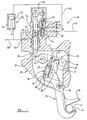
- FIGURE 1 is an illustrative cross sectional view through an assembly in accordance with the invention;
- FIGURE 2 is an illustrative view of the assembly of figure 1 in a fluid circuit.
-
- Referring to the drawings, an
assembly 10 is shown for retaining acatch member 11 in a first latched condition as shown in full lines in figure 1 and for releasing thecatch member 11 for movement to a second unlatched condition. - In this example, the
catch member 11 comprises a part of an undercarriage well door of an aircraft, alatch member 12 of theassembly 10 being operable when in the latched position shown, to retain the door in a closed condition. - The
latch member 12 is pivotable about a first fixed pivotal axis B and has aformation 14 of generally hook configuration adapted to co-operate with thecatch member 11 to retain thecatch member 11 when thelatch member 12 is in the latched position, and arocker member 16 pivotable about a second fixed pivotal axis A. Thelatch member 12 and therocker member 16 are interconnected by a resilient biasing means 18 which acts by pulling thelatch member 12 and therocker member 16 towards one another to retain thelatch member 12 in its latched position and therocker member 16 in the position shown. - Thus the
latch member 12 is unable to rotate clockwise further as anib part 17 thereof is abutted by anabutment part 19 carried on therocker member 16, and anti-clockwise movement of thelatch member 12 about axis B is resisted by thecatch member 11. The resilient biasing means 18 acts between a connection point C of therocker member 16 which is located between the second pivot axis A and theabutment part 19, and a connection point D of thelatch member 12 which is located on an opposite side of the first pivot axis B to thehook formation 14. - It can be seen in the drawings that the
abutment part 19 of therocker member 16 comprises a roller so that as thenib part 17 andabutment part 19 of therocker members 16 relatively move, there is no frictional resistance between them. When thelatch member 12 is in the latched position shown, movement of therocker member 16 clockwise about its pivotal axis A is resisted by astop 21 carried on therocker member 16, which engages a top surface of thenib part 17. - The
assembly 10 further comprises anactuating means 25 which may be operated to move therocker member 16 anticlockwise about the second pivotal axis A against the force of the resilient biasing means 18. By virtue of the points of connection C, D of the resilient biasing means 18, such movement of therocker member 16 will thus result in thelatch member 12 pivoting about the first pivotal axis B clockwise to an unlatched position to release thecatch member 11. This is achieved as theabutment part 19 of therocker member 16 will be moved upwardly away from thenib part 17 of thelatch member 12, whichnib part 17 will thus tend to move into the space previously occupied by theabutment part 19. Clockwise movement of thenib part 17 is arrested as thenib part 17 engages a pin P provided by thehousing 22, at which position thecatch member 11 will be released. - The resilient biasing means 18 comprises in this example, first 26 and second 27 relatively movable parts with a
spring 28 acting between them. The first part 26 (connected at D to the latch member 12) is slideable within the second part 27 (connected at C to the rocker member 16) such that as therocker member 16 moves away from thelatch member 12, thespring 28 is increasingly compressed between the twoparts rocker member 16 anticlockwise about the second axis A exceeds a threshold position, a stop 30 of thefirst part 26 will engage ashoulder 31 of thesecond part 27 for a purpose hereinafter explained. When the stop 30 andshoulder 31 are engaged, they provide a stop means which locks the first and second relativelymovable parts - The resilient biasing means 18 is pivotally connected to the
rocker member 16 at C on an opposite side of the pivotal axis A to where the actuating means 25 operates. Therocker member 16 thus comprises alever part 32 on which the actuating means 25 bears, the actuating means 25 being carried at an end of apiston 36 which is received in acylinder 37 to which pressurised fluid, preferably hydraulic fluid may be supplied as hereinafter explained, to move thepiston 36 in thecylinder 37 to act upon thelever part 32 of therocker member 16 to move therocker member 16 to release thecatch member 11. - Hydraulic fluid may be fed to the
cylinder 37 from a main valve means 40 which is shown in figure 2, along asupply line 41 when a spool of the main valve means 40 in the position indicated at I. Thus fluid pumped to the main valve means 40 will flow through the main valve means 40, alongline 41 and to aport 42 of thehousing 22 of theassembly 10, whichinlet 42 connects with thecylinder 37 through acavity 44 which contains acheck valve 45. The fluid will thus act on one side S1 of thepiston 36.
nearly immediately in response to movement of therocker member 16. In the event that thelatch member 12 is frozen or otherwise jammed in its first condition as seen in figure 1, when the stop 30 andshoulder 31 engage, the resilient biasing means 18 will act as a rigid strut positively to cause movement of thelatch member 12 to release thecatch member 11 before thefurther actuator 55 operates. - When it is desired to close the undercarriage well door, the main valve means 40 is moved to the position shown at II in figure 2. Fluid will then flow along the "return"
line 58 which thus acts as a supply line to deliver pressurised fluid to thefurther actuator 55, and as a result thepiston 53 thereof moves to move thecatch member 11 back towards its first condition shown in figure 1. - Fluid expelled from the one side of the
piston 53 will be fed alongline 51 toport 50 where the fluid will act on thecheck valve 45 which will still be operated upon by theoperating part 47 carried by theactuating means 25. Thus fluid may flow past thecheck valve 45 toport 42 of thehousing 22 from where the fluid may flow back to the main valve means 40 and hence to tank 59. - As the
catch member 11 approaches its first condition, thecatch member 11 will engage anupper jaw part 65 of thelatch member 12 to move thelatch member 12 back to the position shown in figure 1. - Fluid which will simultaneously be fed to
port 62 from theline 58, will act on the underside S2 ofpiston 36 to move the actuating means 25 clear of therocker member 16 to permit the rocker member andlatch member 12 to be moved back to the positions shown in Figure 1. - Alternatively or additionally by virtue of the resilient biasing means 18 the
catch member 11 may act on thelatch member 12 which will causerocker member 16 movement, which will result in therocker member 16 urging the actuating means 25 in a second direction opposite to the first direction. In each - Thus when the spool of the main valve means 40 is in the position I, the actuating means 25 may be moved as indicated above to move the
rocker member 16 anti clockwise about axis A to release thecatch member 11. - The
piston 36 carries anoperating part 47 via alinkage 48, so that theoperating part 47 moves with and parallel to thepiston 36. - When the actuating means 25 and thus the
rocker member 16 have moved a threshold amount, theoperating part 47 is adapted to operate on thecheck valve 45 incavity 44 to move the check valve against a spring to an open position in which thefluid entering port 42 may flow past thecheck valve 45 into apassage 49 and to anotherport 50 of thehousing 22 of theassembly 10. From there the fluid flows along aline 51 to one side of apiston 53 of afurther actuator 55, to effect a movement of thepiston 53, outwardly of itscylinder 54 as seen in the drawings. - The
piston 53 of thefurther actuator 55 is connected by a mechanical linkage (not shown) to the undercarriage well door having thecatch member 11 so that when thecatch member 11 is released, the door may be opened by thefurther actuator 55. - The
further actuator 55 is a so called double actuating actuator and fluid expelled from the opposite side of thepiston 53 flows via areturn line 58 through the main valve means 40 to areservoir 59 from where the fluid may be drawn by apump 60 for use, as does excess fluid from thecylinder 37 of the actuating means which flows to aport 62 in communication withline 58. - As mentioned above, the relative movement between the two
parts shoulder 31. Preferably the stop 30 andshoulder 31 engage before the operatingpart 47 operates on thecheck valve 45 so that thefurther actuator 55 does not commence premature movement of thecatch member 11. It will be appreciated that normally the force exerted by thespring 28 of the resilient biasing means 18 will be sufficient to cause thelatch member 12 to move case,piston 36 movement will move operatingpart 47 out of operating engagement with thecheck valve 45, although excess fluid fed toport 50, if of sufficient pressure, may opencheck valve 45 against its spring to permit excess fluid from thefurther activator 55 to return totank 59 alongline 41. - Various other modifications are possible without departing from the scope of the invention.
- For example, the
latch member 12 androcker member 16 need not be of the configurations described but alternative configurations are no doubt possible. The arrangement shown and described above does however provide for a greater force to be available to release thecatch member 11 which is an essential safety feature where the invention is applied to operate an aircraft uplock assembly. - If desired some means other than
further actuator 55 may be employed to move thecatch member 11 in which case further actuator 55, operatingpart 47 etc. need not be provided. However the arrangement described provides for the safe and reliable hydraulic sequencing of the movement of thecatch member 11 and the operation of the latchingassembly 10. - The hydraulic circuit in which the
assembly 10 is provided my be of an alternative configuration and may have additional components such as one way/check valves, filters and the like which are not shown or described herein or indeed need not be a hydraulic circuit as described but may be another fluid circuit. However, the circuit shown and described has been found to be virtually immune from pressure spikes which can occur in a complex aircraft system for example. - Although the invention has been described in relation to an uplock assembly and fluid sequencing means for an undercarriage well door, the invention has other applications such as to an uplock for an undercarriage itself for example only.
Claims (13)
- An assembly (10) for retaining a catch member (11) in a first condition and for releasing the catch member (11) for movement to a second condition, the assembly including a latch member (12) pivotable about a first pivotal axis (B) and having a formation (14) adapted to co-operate with the catch member (11) to retain the catch member (11) when the latch member (12) is in a latched position, and a rocker member (16) pivotable about a second pivotal axis (A), the latch member (12) and the rocker member (16) interacting to retain the latch member (12) in its latched position, the assembly (10) further including actuating means (25) to move the rocker member (16) about the second pivotal axis (A) to allow the latch member (12) to be pivoted about the first pivotal axis (B) to an unlatched position to release the catch member (11) characterised in that the latch member (12) and the rocker member (16) are interconnected by a resilient biasing means (18), the resilient biasing means (18) including first (26) and second (27) relatively movable parts with a spring (28) acting between them and there being a stop means (30, 31) which locks the first and second relatively movable parts (26, 27) upon operation of the actuating means (25) resulting in a movement of the rocker member (16) about the second pivotal axis (A) beyond a threshold position.
- An assembly according to claim 1 characterised in that the spring (28) is a compression spring which is increasingly compressed until the stop means (30, 31) operates.
- An assembly according to claim 1 or claim 2 characterised in that the resilient biasing means (18) is connected to the rocker member (16) at one side of the second pivotal axis (A) and the actuating means (25) is operated at an opposite side of the first pivotal axis (A), the rocker member (16) comprising an abutment (19) located on the same side of the second pivotal axis (A) as the point of connection (C) of the resilient biasing means (18), which abutment (19) co-operates with a part (17) of the latch member (12) to prevent the latch member (12) rotating about the first pivotal axis (B) beyond the latched position when the catch member (11) is retained, and the abutment (19) being movable when the actuating means (25) is actuated to permit the latch member (12) to pivot about the first pivotal axis (B) to release the catch member (11).
- An assembly according to any one of the preceding claims characterised in that the actuating means (25) is fluid operated, the assembly (10) comprising main valve means (40) operable to permit fluid to act to move the actuating means (25) in a first direction to release the catch member (11) for movement to the second condition.
- An assembly according to claim 4 characterised in that the main valve means (40) is operable to permit fluid to act to move the actuating means (25) in a second direction by the rocker member (16) when the catch member (11) is returned towards the first condition.
- An assembly according to claim 4 or claim 5 characterised in that the actuating means (25) is carried by a piston of a piston (36) and cylinder (37) arrangement, fluid acting on the piston (36) to move the piston (36) and hence the actuating means (25) in at least the first direction.
- An assembly according to claim 6 characterised in that the piston (36) carries an operating part (47) which is operable to operate a check valve (45) to open the check valve (45) as the actuating means (25) moves in the first direction to permit fluid to flow simultaneously to a further actuator (55).
- An assembly according to claim 7 characterised in that the further actuator (55) is operable to move the catch member (11) from the first to the second condition when the catch member (11) is released.
- An assembly according to claim 7 or claim 8 characterised in that the further actuator (55) is operable to move the catch member (11) from the second to the first retained condition.
- An assembly according to any one of the preceding claims characterised in that the catch member (11) comprises a part of a door assembly of an aircraft or a part of an undercarriage of an aircraft.
- A combination of an assembly according to any one of the preceding claims and a fluid sequencing means for operation of the assembly, the fluid sequencing means including a piston (36) and cylinder (37) arrangement, the piston (36) carrying the actuating means (25), a main valve (40) means to supply fluid to the cylinder (37) to move the piston (36) and hence the actuating means (25) when the main valve means (40) is in a first operating condition, and the piston (36) carrying an operating part (47) which is operable to operate a check valve (45) to open the check valve (45) as the actuating means (25) moves in a first direction to permit fluid to flow simultaneously to a further actuator (55).
- A combination according to claim 11 characterised in that a piston (53) of the further actuator (55) is moved in a first direction by fluid acting on one side of the piston (53) when the main valve means (40) is in the first operating condition, and fluid from the one side of the piston (53) being able to pass back past the main valve means (40) when the piston (53) is moved in a second direction opposite to the first direction.
- A combination according to claim 12 characterised in that the piston (53) of the further actuator (55) is moved in the second direction when fluid acts upon an opposite side of the piston (53) to the one side when the main valve means (40) is in a second operating condition.
Applications Claiming Priority (2)
| Application Number | Priority Date | Filing Date | Title |
|---|---|---|---|
| GBGB9802458.1A GB9802458D0 (en) | 1998-02-06 | 1998-02-06 | Uplock assembly |
| GB9802458 | 1998-02-06 |
Publications (3)
| Publication Number | Publication Date |
|---|---|
| EP0934874A2 EP0934874A2 (en) | 1999-08-11 |
| EP0934874A3 EP0934874A3 (en) | 1999-10-27 |
| EP0934874B1 true EP0934874B1 (en) | 2003-04-16 |
Family
ID=10826510
Family Applications (1)
| Application Number | Title | Priority Date | Filing Date |
|---|---|---|---|
| EP99102097A Expired - Lifetime EP0934874B1 (en) | 1998-02-06 | 1999-02-02 | Aircraft undercarriage door latching assembly |
Country Status (6)
| Country | Link |
|---|---|
| US (1) | US6168113B1 (en) |
| EP (1) | EP0934874B1 (en) |
| CA (1) | CA2260672A1 (en) |
| DE (1) | DE69906840T2 (en) |
| ES (1) | ES2197531T3 (en) |
| GB (1) | GB9802458D0 (en) |
Families Citing this family (27)
| Publication number | Priority date | Publication date | Assignee | Title |
|---|---|---|---|---|
| DE10020825B4 (en) * | 2000-04-28 | 2006-08-24 | Eurocopter Deutschland Gmbh | Method and device for closing a door of an aircraft |
| US6315336B1 (en) * | 2000-05-30 | 2001-11-13 | Summit Manufacturing, Inc. | Motorized self-cleaning oven latch |
| FR2836668B1 (en) * | 2002-03-04 | 2004-12-03 | Messier Bugatti | ATTACHMENT DEVICE, IN PARTICULAR FOR ATTACHING AN AIRCRAFT LANDING GEAR OR AN AIRCRAFT LANDING GEAR HATCH, AND METHOD FOR OPERATING THE SAID DEVICE |
| FR2836669B1 (en) * | 2002-03-04 | 2004-12-03 | Messier Bugatti | HANGING DEVICE, IN PARTICULAR FOR HANGING AN AIRCRAFT LANDING GEAR OR AN AIRCRAFT LANDING GEAR |
| AU2003902273A0 (en) | 2003-05-12 | 2003-05-29 | Freund, Carlos Alfredo | Barrier release system |
| GB2408066A (en) * | 2003-11-13 | 2005-05-18 | Messier Dowty Ltd | Latch comprising emergency release actuator |
| WO2006081664A1 (en) * | 2005-02-03 | 2006-08-10 | Héroux-Devtek Inc. | Alternative uplock release assembly |
| US8136272B2 (en) * | 2005-07-13 | 2012-03-20 | Harnischfeger Technologies, Inc. | Dipper door latch with locking mechanism |
| US8590180B2 (en) | 2005-07-13 | 2013-11-26 | Harnischfeger Technologies, Inc. | Dipper door latch with locking mechanism |
| US20070107269A1 (en) * | 2005-07-13 | 2007-05-17 | Harnischfeger Technologies, Inc. | Dipper door latch with locking mechanism |
| GB2460088B (en) * | 2008-05-16 | 2012-05-09 | Ge Aviat Systems Ltd | Locking assembly |
| US9211946B2 (en) | 2011-10-01 | 2015-12-15 | The Boeing Company | Wing fold system with latch pins through multiple mating lugs |
| US9290260B2 (en) | 2011-10-01 | 2016-03-22 | The Boeing Company | Wing fold controller |
| US9296469B2 (en) | 2011-10-01 | 2016-03-29 | The Boeing Company | Horizontal folding wingtip |
| US9499252B2 (en) | 2011-10-01 | 2016-11-22 | The Boeing Company | Wing fold controller |
| FR2982240B1 (en) * | 2011-11-09 | 2013-12-13 | Messier Bugatti Dowty | METHOD FOR DEPLOYING AIRCRAFT AIRCRAFT LIGHTERS IN EMERGENCY MODE. |
| GB2494782B (en) | 2012-09-17 | 2013-09-18 | Messier Dowty Ltd | Landing gear assembly |
| US9469392B2 (en) | 2012-10-30 | 2016-10-18 | The Boeing Company | Wing fold system rotating latch |
| US9415857B2 (en) | 2012-10-30 | 2016-08-16 | The Boeing Company | Wing fold system |
| GB2518604A (en) | 2013-09-18 | 2015-04-01 | Airbus Operations Ltd | Drive system for aircraft landing gear |
| GB2528966A (en) * | 2014-08-07 | 2016-02-10 | Airbus Operations Ltd | Landing gear drive system |
| EP3135581B1 (en) * | 2015-08-25 | 2018-03-21 | Safran Landing Systems UK Limited | Aircraft landing gear assembly |
| KR102658525B1 (en) * | 2016-10-06 | 2024-04-18 | 삼성전자주식회사 | Unmanned aerial vehicle and operating method thereof |
| CN106428518B (en) * | 2016-11-29 | 2018-08-07 | 四川凌峰航空液压机械有限公司 | Hatch door uplock turnover device |
| US11498662B2 (en) * | 2019-10-09 | 2022-11-15 | Goodrich Corporation | Electrically operated landing gear lock system |
| US11511852B2 (en) | 2020-07-27 | 2022-11-29 | Goodrich Corporation | Mechanically operated landing gear uplock systems and methods |
| EP3945019A1 (en) * | 2020-07-27 | 2022-02-02 | Goodrich Corporation | Mechanically operated landing gear uplock systems and methods |
Family Cites Families (8)
| Publication number | Priority date | Publication date | Assignee | Title |
|---|---|---|---|---|
| FR2036686B1 (en) * | 1969-01-31 | 1974-02-22 | Messier Hispano Sa | |
| FR2061559B2 (en) * | 1969-06-27 | 1974-06-14 | Messier Hispano Sa | |
| FR2270143B1 (en) * | 1974-05-07 | 1976-10-15 | Messier Hispano Sa | |
| US4058331A (en) * | 1976-10-29 | 1977-11-15 | The United States Of America As Represented By The Secretary Of The Air Force | Remotely actuated two stage structural latch |
| US4159137A (en) * | 1977-12-05 | 1979-06-26 | Tridair Industries | Adjustable multipivot panel latch |
| GB2161202A (en) | 1984-07-05 | 1986-01-08 | Dowty Rotol Ltd | Locking means for retractable devices |
| US4927996A (en) * | 1988-05-23 | 1990-05-22 | Robertshaw Controls Company | Cooking apparatus, door latching construction therefor and methods of making the same |
| US5022691A (en) * | 1990-08-17 | 1991-06-11 | Whiting Roll-Up Door Mfg. Corp. | Side lock for a roll-up door |
-
1998
- 1998-02-06 GB GBGB9802458.1A patent/GB9802458D0/en not_active Ceased
-
1999
- 1999-02-02 ES ES99102097T patent/ES2197531T3/en not_active Expired - Lifetime
- 1999-02-02 DE DE69906840T patent/DE69906840T2/en not_active Expired - Fee Related
- 1999-02-02 EP EP99102097A patent/EP0934874B1/en not_active Expired - Lifetime
- 1999-02-04 CA CA002260672A patent/CA2260672A1/en not_active Abandoned
- 1999-02-04 US US09/243,984 patent/US6168113B1/en not_active Expired - Lifetime
Also Published As
| Publication number | Publication date |
|---|---|
| CA2260672A1 (en) | 1999-08-06 |
| US6168113B1 (en) | 2001-01-02 |
| GB9802458D0 (en) | 1998-04-01 |
| DE69906840T2 (en) | 2003-11-13 |
| EP0934874A2 (en) | 1999-08-11 |
| EP0934874A3 (en) | 1999-10-27 |
| DE69906840D1 (en) | 2003-05-22 |
| ES2197531T3 (en) | 2004-01-01 |
Similar Documents
| Publication | Publication Date | Title |
|---|---|---|
| EP0934874B1 (en) | Aircraft undercarriage door latching assembly | |
| US8814094B2 (en) | Locking mechanism with bi-modal actuator | |
| US5735557A (en) | Lock mechanism | |
| CA2337337C (en) | Multi-line back pressure control system | |
| CN108884784B (en) | Thrust reverser actuation | |
| DE60211421T2 (en) | Hydraulic actuation system for use with a cargo door of an aircraft with a cam lock | |
| US20110010915A1 (en) | Safety Locking Device | |
| EP1914163B1 (en) | Architecture of a hydraulic system for manoeuvring aircraft landing gear | |
| US9689139B2 (en) | Quick coupler | |
| US5431085A (en) | Thrust reverser actuator | |
| US4573649A (en) | Integrated alternate gear extension and ground-crew door opening/closing system for an aircraft | |
| US6792844B1 (en) | Hydraulic system for aircraft landing gear | |
| EP3594508B1 (en) | Hydraulic circuit for supplying a cylinder, in particular used to manoeuvre a hold door of an aircraft | |
| US5040747A (en) | Gripping and locking arrangement for aircraft flap doors or undercarriages | |
| CN112520020A (en) | Logic coordination valve for controlling upper lock of landing gear door | |
| US2351284A (en) | Aircraft construction | |
| CN109515694B (en) | Control system for automatically preventing non-instruction opening of landing gear cabin door | |
| US4282909A (en) | Aerial refueling device | |
| US7350873B2 (en) | Backboard bar with adjusting closure | |
| US20220034061A1 (en) | I-lock coupler | |
| JP2603369Y2 (en) | Sliding control device for cargo boxes in freight vehicles | |
| US11136940B2 (en) | Hydraulic thrust reverser actuation system | |
| DE10228978B4 (en) | Locking and locking system for doors or flaps | |
| US11858650B2 (en) | Manually actuated hydraulic circuit for ram air turbine (RAT) restow | |
| CN214084739U (en) | Trigger type coordination valve for upper position lock of cabin door |
Legal Events
| Date | Code | Title | Description |
|---|---|---|---|
| PUAI | Public reference made under article 153(3) epc to a published international application that has entered the european phase |
Free format text: ORIGINAL CODE: 0009012 |
|
| AK | Designated contracting states |
Kind code of ref document: A2 Designated state(s): DE ES FR GB IT |
|
| AX | Request for extension of the european patent |
Free format text: AL;LT;LV;MK;RO;SI |
|
| PUAL | Search report despatched |
Free format text: ORIGINAL CODE: 0009013 |
|
| AK | Designated contracting states |
Kind code of ref document: A3 Designated state(s): AT BE CH CY DE DK ES FI FR GB GR IE IT LI LU MC NL PT SE |
|
| AX | Request for extension of the european patent |
Free format text: AL;LT;LV;MK;RO;SI |
|
| RIC1 | Information provided on ipc code assigned before grant |
Free format text: 6B 64C 25/26 A, 6E 05C 3/24 B |
|
| 17P | Request for examination filed |
Effective date: 19991019 |
|
| AKX | Designation fees paid |
Free format text: DE ES FR GB IT |
|
| 17Q | First examination report despatched |
Effective date: 20010508 |
|
| GRAH | Despatch of communication of intention to grant a patent |
Free format text: ORIGINAL CODE: EPIDOS IGRA |
|
| GRAH | Despatch of communication of intention to grant a patent |
Free format text: ORIGINAL CODE: EPIDOS IGRA |
|
| GRAA | (expected) grant |
Free format text: ORIGINAL CODE: 0009210 |
|
| AK | Designated contracting states |
Designated state(s): DE ES FR GB IT |
|
| REG | Reference to a national code |
Ref country code: GB Ref legal event code: FG4D |
|
| REF | Corresponds to: |
Ref document number: 69906840 Country of ref document: DE Date of ref document: 20030522 Kind code of ref document: P |
|
| ET | Fr: translation filed | ||
| REG | Reference to a national code |
Ref country code: ES Ref legal event code: FG2A Ref document number: 2197531 Country of ref document: ES Kind code of ref document: T3 |
|
| PLBE | No opposition filed within time limit |
Free format text: ORIGINAL CODE: 0009261 |
|
| STAA | Information on the status of an ep patent application or granted ep patent |
Free format text: STATUS: NO OPPOSITION FILED WITHIN TIME LIMIT |
|
| 26N | No opposition filed |
Effective date: 20040119 |
|
| PGFP | Annual fee paid to national office [announced via postgrant information from national office to epo] |
Ref country code: FR Payment date: 20060202 Year of fee payment: 8 |
|
| PGFP | Annual fee paid to national office [announced via postgrant information from national office to epo] |
Ref country code: ES Payment date: 20060215 Year of fee payment: 8 |
|
| PGFP | Annual fee paid to national office [announced via postgrant information from national office to epo] |
Ref country code: IT Payment date: 20060228 Year of fee payment: 8 Ref country code: DE Payment date: 20060228 Year of fee payment: 8 |
|
| GBPC | Gb: european patent ceased through non-payment of renewal fee |
Effective date: 20070202 |
|
| REG | Reference to a national code |
Ref country code: FR Ref legal event code: ST Effective date: 20071030 |
|
| PG25 | Lapsed in a contracting state [announced via postgrant information from national office to epo] |
Ref country code: DE Free format text: LAPSE BECAUSE OF NON-PAYMENT OF DUE FEES Effective date: 20070901 |
|
| PG25 | Lapsed in a contracting state [announced via postgrant information from national office to epo] |
Ref country code: GB Free format text: LAPSE BECAUSE OF NON-PAYMENT OF DUE FEES Effective date: 20070202 Ref country code: FR Free format text: LAPSE BECAUSE OF NON-PAYMENT OF DUE FEES Effective date: 20070228 |
|
| REG | Reference to a national code |
Ref country code: ES Ref legal event code: FD2A Effective date: 20070203 |
|
| PG25 | Lapsed in a contracting state [announced via postgrant information from national office to epo] |
Ref country code: ES Free format text: LAPSE BECAUSE OF NON-PAYMENT OF DUE FEES Effective date: 20070203 |
|
| PGFP | Annual fee paid to national office [announced via postgrant information from national office to epo] |
Ref country code: GB Payment date: 20060109 Year of fee payment: 8 |
|
| PG25 | Lapsed in a contracting state [announced via postgrant information from national office to epo] |
Ref country code: IT Free format text: LAPSE BECAUSE OF NON-PAYMENT OF DUE FEES Effective date: 20070202 |