EP0934716A2 - Mechanism for chair - Google Patents
Mechanism for chair Download PDFInfo
- Publication number
- EP0934716A2 EP0934716A2 EP99300780A EP99300780A EP0934716A2 EP 0934716 A2 EP0934716 A2 EP 0934716A2 EP 99300780 A EP99300780 A EP 99300780A EP 99300780 A EP99300780 A EP 99300780A EP 0934716 A2 EP0934716 A2 EP 0934716A2
- Authority
- EP
- European Patent Office
- Prior art keywords
- spring
- mechanism according
- support
- seat
- chair
- Prior art date
- Legal status (The legal status is an assumption and is not a legal conclusion. Google has not performed a legal analysis and makes no representation as to the accuracy of the status listed.)
- Granted
Links
- 230000006835 compression Effects 0.000 claims abstract description 12
- 238000007906 compression Methods 0.000 claims abstract description 12
- 230000000694 effects Effects 0.000 claims description 6
- 230000002441 reversible effect Effects 0.000 claims description 3
- 229910000831 Steel Inorganic materials 0.000 claims description 2
- 239000010959 steel Substances 0.000 claims description 2
- 230000001419 dependent effect Effects 0.000 claims 2
- 230000000750 progressive effect Effects 0.000 description 2
- 208000027418 Wounds and injury Diseases 0.000 description 1
- 230000001944 accentuation Effects 0.000 description 1
- 238000013459 approach Methods 0.000 description 1
- 230000006378 damage Effects 0.000 description 1
- 208000014674 injury Diseases 0.000 description 1
- 239000002184 metal Substances 0.000 description 1
Images


Classifications
-
- A—HUMAN NECESSITIES
- A47—FURNITURE; DOMESTIC ARTICLES OR APPLIANCES; COFFEE MILLS; SPICE MILLS; SUCTION CLEANERS IN GENERAL
- A47C—CHAIRS; SOFAS; BEDS
- A47C1/00—Chairs adapted for special purposes
- A47C1/02—Reclining or easy chairs
- A47C1/031—Reclining or easy chairs having coupled concurrently adjustable supporting parts
- A47C1/032—Reclining or easy chairs having coupled concurrently adjustable supporting parts the parts being movably-coupled seat and back-rest
- A47C1/03294—Reclining or easy chairs having coupled concurrently adjustable supporting parts the parts being movably-coupled seat and back-rest slidingly movable in the base frame, e.g. by rollers
-
- A—HUMAN NECESSITIES
- A47—FURNITURE; DOMESTIC ARTICLES OR APPLIANCES; COFFEE MILLS; SPICE MILLS; SUCTION CLEANERS IN GENERAL
- A47C—CHAIRS; SOFAS; BEDS
- A47C1/00—Chairs adapted for special purposes
- A47C1/02—Reclining or easy chairs
- A47C1/031—Reclining or easy chairs having coupled concurrently adjustable supporting parts
- A47C1/032—Reclining or easy chairs having coupled concurrently adjustable supporting parts the parts being movably-coupled seat and back-rest
- A47C1/03205—Reclining or easy chairs having coupled concurrently adjustable supporting parts the parts being movably-coupled seat and back-rest having adjustable and lockable inclination
- A47C1/03238—Reclining or easy chairs having coupled concurrently adjustable supporting parts the parts being movably-coupled seat and back-rest having adjustable and lockable inclination by means of peg-and-notch or pawl-and-ratchet mechanism
-
- A—HUMAN NECESSITIES
- A47—FURNITURE; DOMESTIC ARTICLES OR APPLIANCES; COFFEE MILLS; SPICE MILLS; SUCTION CLEANERS IN GENERAL
- A47C—CHAIRS; SOFAS; BEDS
- A47C1/00—Chairs adapted for special purposes
- A47C1/02—Reclining or easy chairs
- A47C1/031—Reclining or easy chairs having coupled concurrently adjustable supporting parts
- A47C1/032—Reclining or easy chairs having coupled concurrently adjustable supporting parts the parts being movably-coupled seat and back-rest
- A47C1/03255—Reclining or easy chairs having coupled concurrently adjustable supporting parts the parts being movably-coupled seat and back-rest with a central column, e.g. rocking office chairs
-
- A—HUMAN NECESSITIES
- A47—FURNITURE; DOMESTIC ARTICLES OR APPLIANCES; COFFEE MILLS; SPICE MILLS; SUCTION CLEANERS IN GENERAL
- A47C—CHAIRS; SOFAS; BEDS
- A47C1/00—Chairs adapted for special purposes
- A47C1/02—Reclining or easy chairs
- A47C1/031—Reclining or easy chairs having coupled concurrently adjustable supporting parts
- A47C1/032—Reclining or easy chairs having coupled concurrently adjustable supporting parts the parts being movably-coupled seat and back-rest
- A47C1/03261—Reclining or easy chairs having coupled concurrently adjustable supporting parts the parts being movably-coupled seat and back-rest characterised by elastic means
- A47C1/03272—Reclining or easy chairs having coupled concurrently adjustable supporting parts the parts being movably-coupled seat and back-rest characterised by elastic means with coil springs
Definitions
- This invention relates to a mechanism for a chair of the kind having a base part, and a seat part mounted on the base part so as to be of adjustable inclination against a spring force relative to the horizontal.
- the inclination to the horizontal of the seat may be adjustable against a spring force, by means of a mechanism, between forwardly and rearwardly inclined limits.
- the back may be movable forwardly and rearwardly relative to the seat and it is known to use a so called synchro mechanism which synchronises adjustment of the vertical rake of the back with tilting of the seat, whereby the back moves through a greater angle than the seat, say in accordance with a ratio of 3:2.
- Adjustment of the seat angle and the rake of the back is effected with the user seated on the chair.
- the user leans backwards to cause his of her weight to move the back and the seat against the resistance of the spring force. It is desirable that the spring resistance should be adequate to achieve slow controlled movement but without requiring excessive effort. It is therefore usual to provide an adjustment control to adjust the spring force to suit the weight of the user.
- one object of the invention is to provide a mechanism for a chair which is simple and convenient to operate and comfortable in use.
- an adjustable mechanism for a chair which chair has a base part, and a seat mounted on the base part so as to be of adjustable inclination relative to the horizontal, said mechanism including a spring arrangement disposed in compression to provide a spring force applied in a direction between the base part and the seat part so as to resist said adjustment movement of the seat part, and an adjustment control operable to adjust the disposition of the spring arrangement with reference to extent of compression thereof and also the said direction thereof.
- adjustment of the disposition of the direction of spring force application involves a change in inclination thereof, and this may be attained by lateral movement of one end of the spring arrangement relative to an opposite end thereof.
- the spring arrangement is mounted, or held captive, at said opposite ends thereof between pivotally interconnected upper and lower supports, said lateral movement being effected by adjustment of the relative angular disposition of the lower support relative to the upper support.
- the lower support has a free end region which is engageable with a fulcrum member about which the lower support pivots during movement of the upper and lower supports towards and away from each other, and the said adjustment of the relative angular disposition of the upper and lower supports is effected by adjustment of the position of the fulcrum member.
- the fulcrum member comprises in combination at least one fixed fulcrum element and at least one positionally adjustable fulcrum element arranged such that the said free end region of the lower spring support engages the (or each) fixed element at an initial phase of movement and subsequently engages the (or each) positionally adjustable fulcrum element.
- the fulcrum member and the coacting end region of the lower spring support may take any suitable form but are preferably shaped to accommodate easy, controlled relative movement.
- one or more shaped, e.g. curved projections or rollers or the like may be used for the fulcrum member, and the end region of the lower spring support may comprise one or more curved and/or angled faces.
- the above mentioned arrangement whereby the lower spring support initially contacts one or more fixed fulcrum elements and then contacts one or more positionally adjustable fulcrum elements is preferably achieved by arranging the respective elements in mutually displaced positions and incorporating a linkage which effects movement of the fulcrum member relative to the coacting end region of the lower spring support.
- This linkage may incorporate a cam follower engageable with a cam slot.
- the cam follower may comprise an axle on the said base part, and the cam slot may be provided on the seat part, although other arrangements are also possible.
- the said spring arrangement may comprise a helical coil spring or any other suitable spring arrangement including leaf springs, rubber springs, gas cylinders.
- the chair may also include a back part and this may be connected to the mechanism so that it moves with tilting of the seat part in accordance with any suitable desired relationship.
- a synchro arrangement may be used whereby the back is capable of rearward movement through a greater angle than the seat in accordance with a predetermined ratio (say 3:2), although other arrangements are also possible.
- the back part may be rigidly mounted on the above mentioned upper spring support. This may be achieved via a rigid L-shaped plate member and one limb of this may be firmly anchored within a slot or other means in the upper support.
- the upper spring support may comprise a body part with an attached rearwardly projecting rigid elongate support member which provides support for the back. With this arrangement the back can be adequately supported without requiring a massive structure for the said body part.
- a mechanism for a chair which has a base part, and a seat mounted on the base part so as to be of adjustable inclination relative to the horizontal, said mechanism including a spring arrangement disposed in compression between upper and lower spring supports respectively connected between the base part and the seat part, and a back part supported on the upper spring support, wherein the upper spring support comprises a body part with an attached rearwardly projecting rigid elongate support member which provides support for the back part.
- the elongate support member may comprise a U-shaped steel bar.
- a locking mechanism is preferably provided for holding the seat part relative to the base part in a selected angular relationship and this may comprise at least one tooth member engageable between teeth of a rack or ratchet member.
- a spring may be provided and this may be of reversible effect, preferably under the action of a manual control, whereby in one mode it acts to urge the (or each) tooth member into locking engagement with the rack or ratchet, and in a further mode it acts to urge the (or each) tooth member out of engagement with the rack or ratchet such that disengagement, i.e. unlocking, is possible after removal of transverse force.
- a locking mechanism suitable for use with a mechanism of the kind described above, comprising at least one tooth member engageable between teeth of at least one rack or ratchet member, a spring arrangement operable in two modes respectively to urge the (or each) tooth member into engagement with the (or each) rack or ratchet and to urge the (or each) tooth member out of such engagement on release of retaining force acting on the (or each) said tooth member transversely thereto along the (or each) rack or ratchet, and a control for switching between said modes.
- Fig. 1 shows an office chair having a seat part 1, a base part 2, and a back part 3, all interconnected via a mechanism 4.
- the base part comprises a vertical central support pillar 5 attached at its lower end to a five-arm wheeled floor-engaging structure 6. At its upper end the pillar 5 is attached to a bottom part 7 of the mechanism 4 beneath the seat part 1.
- the pillar 5 contains a gas cylinder height adjusting mechanism which is operated by a manual control (not shown) comprising a cam on a shaft which engages with a valve at the end of the gas cylinder on operation of the shaft by means of a control knob or lever.
- the seat part 1 comprises a padded seat structure on a frame which is attached to a top part 8 of the mechanism 4.
- the back part 3 comprises a padded back structure which is adjustably attached to an upstanding arm of a rigid L-shaped plate member 9 which is attached to an intermediate part 10 of the mechanism.
- this is formed from a number of pivotally interconnected rigid structures, namely the above mentioned bottom and top parts 7, 8, and upper and lower sections 11,12 of the mentioned intermediate part 10.
- the bottom part 7 comprises an upwardly open shell which is mounted rigidly at a central position offset towards a forward end thereof on the top of the pillar 5.
- a front axle 13 is mounted horizontally across the forward end of the bottom part 7 and projects freely at opposite ends.
- a main pivot axle 14 is mounted horizontally across the central region of the bottom part 7.
- the rearward end of the bottom part 7 is open and has two upwardly directed fixed projections 15 with curved top surfaces.
- a forked structure 16 having two rearwardly directed arms 17 with upwardly directed projections 18 with upwardly curved top sections generally of like shape to the fixed projections 15.
- the forked structure 16 can be moved forwardly and rearwardly with the projections 18 on the structure 16 running respectively alongside the fixed projections 15. This movement is effected by rotation of a horizontal square section shaft 19 extending through the bottom part and terminating at one end in a manual control lever 20.
- the arrangement is such that rotation of the shaft 19 with the lever 20 causes the forked structure 16 to move stepwise and to retain its position in one such step when rotation of the shaft 19 is arrested.
- the top part 8 comprises a downwardly open tray or shell which has on opposite sides two downwardly projecting fixtures 21 with mutually aligned generally L-shaped cam slots 22 which run downwardly and forwardly through a curved path. These fixtures 21 are engaged by the opposite projecting ends of the forward axle 13 on the bottom part 7.
- transverse pivot shaft 23 mounted horizontally across the top part 8 (in downwardly projecting features).
- the intermediate part 10 has an upper downwardly open shell section 11 with upwardly directed features 24 at opposite sides with mutually aligned holes therethrough. By means of these features 24, this upper shell section 11 is pivotally mounted on the pivot shaft 23 at the rearward end of the top part 8.
- the lower intermediate section 12 is an upwardly open shell which is pivotally mounted at its rearward end to the rearward end of the upper section 11.
- the lower section 12 At its forward end the lower section 12 has two forwardly projecting arms 26 with downwardly facing ramp surfaces 27 which engage the projections 15, 18 of the bottom part 7 in a manner yet to be described.
- a powerful spring 28 which acts to pivot the sections 11, 12 apart.
- This may comprise a helical coil spring, or any other suitable spring arrangement.
- the upper section 11 has a rearwardly opening slot 29 into which extends the bottom forwardly directed limb 30 of the L-shaped back support 9, such limb 30 being held securely in position by means of fixing bolts engaging holes in the limb 30 and the upper section 11.
- a rigid U-shaped metal rod structure 31 projects rearwardly from the upper section 11 and is mounted at its free ends on the section 11 to provide rigid support for the chair back.
- a ratchet locking mechanism which retains the seat part in a desired angular disposition relative to the horizontal by locking the upper section 11 of the intermediate part 10 in a selected angular position relative to the bottom part 7.
- This locking mechanism comprises a fork 32 on the bottom part 7 which projects rearwardly and supports a tooth member 33 which is engageable with a toothed ratchet 34 mounted at the rear end of the upper intermediate section 11.
- the fork 32 is mounted on a horizontal square section shaft 35 via a cam bush 35a, which shaft projects at one side and terminates in a manual control lever 36.
- the shaft 35 can be rotated between release and locking positions at which the tooth member 33 is respectively free to separate from, and is held in fixed engagement with, the ratchet teeth 34 in a manner described in more detail hereinafter.
- the top part 8 With the tooth member 33 released from the ratchet 34, the top part 8 is free to tilt relative to the horizontal between respective limit positions at which it is inclined at an angle downwards to the front, and at an angle downwards to the rear.
- Movement of the top part 8 occurs under the action of the weight of a person seated on the chair, by shifting his or her weight forwards or rearwards.
- the chair back 3 pivots forwardly and rearwardly in synchronism with tilting of the seat in accordance with a predetermined ratio of relative angular movement (typically 3:2 although any other suitable ratio including 1:1 can be used), this being achieved by pivotting of the upper section 11 with the U-Bar 31 on the pivot bearing 25 on the main pivot axle 14.
- Tilting of the seat rearwardly occurs against the resistance of the springs 28 held captive between the upper and lower sections 11,12 of the intermediate part 10. That is, as the seat tilts rearwardly the springs 28 are compressed to a greater extent.
- top part 8 and the upper and lower sections 11,12 of the intermediate part 10 are pivotally interconnected with each other and with the fixed bottom part 7 by means of a number of pivotal joints, namely:
- the forward axle 13 is at the uppermost and rearmost ends of the cam slots 22, and the ramp surfaces 27 engage the projections 15 in the region of the leading ends of the ramp surfaces.
- the top part 8 pivots about the front axle 13.
- the upper section 11 of the intermediate part 10 pivots about the main axle 14 and the rear axle 23, and at the same time the U-Bar 31 and the upper section 11 pivot on the pivot bearing 25 on the main axle 14 so as to permit the chair back 3 to pivot rearwardly through a greater angle than the pivoting of the seat 1.
- the movable projections 18 are rearwardly displaced relative to the fixed projections 15 whereby initially the ramp surfaces 26 engage the fixed projections 15. After movement of the front axle 13 along the cams 22 the ramp surfaces 27 then engage the movable projections 18.
- the spring tension is pre-set to suit the weight of the person using the chair by adjusting the movable projections 18 with the cam 19a on shaft 19. As these projections 18 are moved rearwardly they have a greater deflecting effect on the ramp surfaces 27 whereby the lower section 12 moves upwardly to compress the spring 28 more readily during the tilting movement of the seat.
- the shape of the projections 15, 18 and ramp surfaces 27 is important to facilitate easy movement and thus these parts will be suitably curved, or otherwise shaped, and the projections may comprise rollers or other structures.
- this utilises a reversible spring bias on the forked tooth carrier 32.
- the tooth member 33 With the shaft 35 rotated in one direction to the locking position the tooth member 33 is strongly spring urged towards the ratchet teeth 34 so that the tooth member 33 engages horizontally a gap between two teeth and thereby prevents relative vertical movement of the ratchet and the tooth member.
- the tooth member 33 With the shaft 35 rotated in the opposite direction the tooth member 33 is weakly spring urged away from the ratchet 34 whereby the tooth member 33 remains trapped between the ratchet teeth whilst a person is sitting on the chair with his or her weight applied rearwardly, but the tooth member 33 moves away from the ratchet 34 when the person shifts his or her weight forwardly to allow tilting to take place.
- the adjustment shaft 35 can be fixed in the locking position.
- adjustment of spring tension can be effected easily by a person seated on the chair without causing discomfort or risk of strain to the person.
- Adjustment of tilt angle can also be effected in a particularly easy, comfortable and strain-free manner, particularly having regard to the ease of use of the locking mechanism and due to the described geometry which ensures that the spring resistance does not increase unduly whilst the person on the chair shifts his or her weight and adjusts the tilt angle.
- the various structural parts of the tilt mechanism can be readily and inexpensively manufactured particularly having regard to the effect of the rearwardly projecting U-shaped member 31 which gives support without requiring a massive costing for the upper section 11.
- the pillar 5 need not be vertical or offset but may be disposed in any suitable manner.
- the initial free movement to transfer contact from the projections 15 to the projections 18 can be achieved with a linkage other than the cam slot 22 e.g. by a rearward slot or otherwise.
- pivots E and D may be coincident.
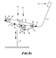
- fulcrum projections 15 and 18 are respectively fixed and adjustable. If desired, these may be both fully adjustable.
Landscapes
- Health & Medical Sciences (AREA)
- Dentistry (AREA)
- General Health & Medical Sciences (AREA)
- Chairs Characterized By Structure (AREA)
- Chairs For Special Purposes, Such As Reclining Chairs (AREA)
Abstract
Description
- Fig. 1
- is a diagrammatic view of a chair incorporating one form of a mechanism according to the invention;
- Fig. 2
- is an exploded perspective view of the mechanism;
- Figs. 3 & 4
- are diagrammatic sketches showing the chair in two extremes of tilt; and
- Fig. 4a
- is a view similar to Fig. 4 showing different positions of fulcrum elements.
Claims (20)
- An adjustable mechanism (4) for a chair, which chair has a base part (2), and a seat (1) mounted on the base part so as to be of adjustable inclination relative to the horizontal, said mechanism (4) including a spring arrangement (11, 12, 28) disposed in compression to provide a spring force applied in a direction between the base part and the seat part so as to resist said adjustment movement of the seat part, and an adjustment control (20) operable to adjust the disposition of the spring arrangement with reference to extent of compression thereof and also the said direction thereof.
- A mechanism according to claim 1 wherein adjustment of the disposition of the direction of spring force application involves a change in inclination thereof.
- A mechanism according to claim 2 wherein adjustment of the disposition of the direction of spring force application is attained by lateral movement of one end of the spring arrangement (28) relative to an opposite end thereof.
- A mechanism according to claim 3 wherein the spring arrangement (28) is mounted at said opposite ends thereof between pivotally interconnected upper and lower supports (11, 12), said lateral movement being effected by adjustment of the relative angular disposition of the lower support (12) relative to the upper support (11).
- A mechanism according to claim 4 wherein the lower support (12) has a free end region which is engageable with a fulcrum member (15, 18) about which the lower support (12) pivots during movement of the upper and lower supports towards and away from each other, and the said adjustment of the relative angular disposition of the upper and lower supports (11, 12) is effected by adjustment of the position of the fulcrum member (15, 18).
- A mechanism according to claim 5 wherein the fulcrum member comprises in combination at least one fixed fulcrum element (15) and at least one positionally adjustable fulcrum element (18) arranged such that the said free end region of the lower spring support engages the (or each) fixed element at an initial phase of movement and subsequently engages the (or each) positionally adjustable fulcrum element.
- A mechanism according to claim 5 or 6 wherein the fulcrum member (15, 18) comprises one or more curved projections or rollers, and the end region (26) of the lower spring support (12) comprises one or more curved or angled faces (27).
- A mechanism according to any one of claims 5 to 7 wherein a linkage (13, 22) is provided to effect movement of the fulcrum member (15, 18) relative to the end region (26) of the lower spring support (12).
- A mechanism according to claim 8 wherein the linkage (13, 22) comprises a cam follower (13) engageable with a cam slot (22).
- A mechanism according to claim 9 wherein the cam follower (13) comprises an axle on the base part and the cam slot (22) is provided on the seat part.
- A chair incorporating a mechanism according to any one of claims 1 to 10 further including a back part (3) connected to the mechanism (4) so as to move with tilting of the seat part (1).
- A chair according to claim 11 wherein the back part (3) is connected to the mechanism (4) with a synchro arrangement whereby the back is capable of rearward movement through a greater angle than the seat.
- A chair according to claim 11 or 12 when dependent on claim 4 wherein the back part (3) is rigidly mounted on the said upper spring support (11) via a rigid L-shaped plate member (9).
- A chair according to claim 11 or 12, when dependent on claim 4, or claim 13, wherein the upper spring support (11) comprises a body part with an attached rearwardly projecting rigid elongate support member (31) which provides support for the back.
- A mechanism for a chair which has a base part (2) , and a seat (1) mounted on the base part so as to be of adjustable inclination relative to the horizontal, said mechanism including a spring arrangement (28) disposed in compression between upper and lower spring supports (11, 12) respectively connected between the base part and the seat part, and a back part (3) supported on the upper spring support (11), wherein the upper spring support (11) comprises a body part with an attached rearwardly projecting rigid elongate support member (31) which provides support for the back part.
- A mechanism according to claim 15 wherein the elongate support member comprises a U-shaped steel bar (31).
- A mechanism according to claim 15 or 16 wherein a locking mechanism is provided for holding the seat part relative to the base part in a selected angular relationship.
- A mechanism according to claim 17 wherein the locking mechanism comprises at least one tooth member (33) engageable between teeth of a rack or ratchet member (34).
- A mechanism according to claim 18 further including a spring of reversible effect whereby in one mode it acts to urge the (or each) tooth member into locking engagement with the rack or ratchet, and in a further mode it acts to urge the (or each) tooth member out of engagement with the rack or ratchet.
- A locking mechanism, suitable for use with a mechanism according to claim 17, comprising at least one tooth member engageable between teeth of at least one rack or ratchet member, a spring arrangement operable in two modes respectively to urge the (or each) tooth member into engagement with the (or each) rack or ratchet and to urge the (or each) tooth member out of such engagement on release of retaining force acting on the (or each) said tooth member transversely thereto along the (or each) rack or ratchet, and a control for switching between said modes.
Applications Claiming Priority (2)
| Application Number | Priority Date | Filing Date | Title |
|---|---|---|---|
| GBGB9802447.4A GB9802447D0 (en) | 1998-02-04 | 1998-02-04 | Mechanism for chair |
| GB9802447 | 1998-02-04 |
Publications (3)
| Publication Number | Publication Date |
|---|---|
| EP0934716A2 true EP0934716A2 (en) | 1999-08-11 |
| EP0934716A3 EP0934716A3 (en) | 2001-10-04 |
| EP0934716B1 EP0934716B1 (en) | 2005-07-27 |
Family
ID=10826501
Family Applications (1)
| Application Number | Title | Priority Date | Filing Date |
|---|---|---|---|
| EP99300780A Expired - Lifetime EP0934716B1 (en) | 1998-02-04 | 1999-02-03 | Mechanism for chair |
Country Status (5)
| Country | Link |
|---|---|
| US (1) | US6238000B1 (en) |
| EP (1) | EP0934716B1 (en) |
| CA (1) | CA2260728C (en) |
| DE (1) | DE69926274D1 (en) |
| GB (2) | GB9802447D0 (en) |
Cited By (8)
| Publication number | Priority date | Publication date | Assignee | Title |
|---|---|---|---|---|
| EP1060694A1 (en) * | 1999-06-17 | 2000-12-20 | König + Neurath AG | Chair, particularly office-chair |
| WO2002091880A1 (en) | 2001-05-12 | 2002-11-21 | Röder Haworth Büro-Sitzmöbel Gmbh | Office chair |
| WO2003030688A1 (en) * | 2000-10-06 | 2003-04-17 | Ghsp, Inc. | Chair control |
| WO2006103000A1 (en) * | 2005-03-26 | 2006-10-05 | Armin Sander | Seat in particular office chair |
| WO2006114250A1 (en) | 2005-04-28 | 2006-11-02 | Imarc S.P.A. | Device for adjusting the reclinning force in office chair mechanisms |
| EP2250940A2 (en) * | 2009-05-13 | 2010-11-17 | Bock-1 GmbH & Co. KG | Synchronisation mechanism |
| CN103237479A (en) * | 2010-12-03 | 2013-08-07 | 伊马克公司 | Office chair mechanism provided with device for adjusting swivel force |
| ITVE20130034A1 (en) * | 2013-07-03 | 2015-01-04 | Imarc Spa | DEVICE FOR QUICK ASSEMBLY OF A BACKREST ON A MECHANISM FOR OFFICE CHAIRS |
Families Citing this family (28)
| Publication number | Priority date | Publication date | Assignee | Title |
|---|---|---|---|---|
| DE10125994A1 (en) * | 2001-05-18 | 2002-11-21 | Bock 1 Gmbh & Co | Synchronous mechanism for a correlated movement of the seat backrest of an office chair |
| JP4137536B2 (en) * | 2002-07-03 | 2008-08-20 | コクヨ株式会社 | Chair |
| CN1984583A (en) * | 2004-06-14 | 2007-06-20 | 维特拉专利股份公司 | Seat with synchronous mechanism |
| DE102005017143B4 (en) * | 2005-04-13 | 2007-06-21 | Bock 1 Gmbh & Co. Kg | Device for seat tilt adjustment of a chair |
| US8061775B2 (en) * | 2005-06-20 | 2011-11-22 | Humanscale Corporation | Seating apparatus with reclining movement |
| DE102009009287A1 (en) * | 2009-02-17 | 2010-09-09 | Uhlenbrock, Christel | Seating furniture, in particular office swivel chair |
| US8272692B1 (en) * | 2009-10-26 | 2012-09-25 | Epperson Ronald B | Office chair having tiltable seat and back |
| WO2012000139A1 (en) * | 2010-07-02 | 2012-01-05 | Chen Qiankui | Chair chassis with adjusting leaning force |
| EP2630894A4 (en) * | 2010-10-19 | 2014-11-12 | Okamura Corp | Chair with armrest |
| DE202012002288U1 (en) * | 2012-03-08 | 2012-05-11 | Walter Knoll Ag & Co. Kg | functional chair |
| US9504326B1 (en) | 2012-04-10 | 2016-11-29 | Humanscale Corporation | Reclining chair |
| US9198514B2 (en) | 2012-05-23 | 2015-12-01 | Hni Technologies Inc. | Chair with pivot function and method of making |
| USD707995S1 (en) | 2012-05-23 | 2014-07-01 | Hni Technologies Inc. | Chair |
| DE202014100062U1 (en) * | 2014-01-08 | 2015-04-10 | Innotec Motion GmbH | Seating furniture with springy backrest |
| US10244869B2 (en) * | 2014-09-23 | 2019-04-02 | Stadium Holding, Inc. | Stadium chair |
| CA2981528C (en) | 2015-04-13 | 2025-09-23 | Steelcase Inc. | Seating arrangement |
| US11259637B2 (en) | 2015-04-13 | 2022-03-01 | Steelcase Inc. | Seating arrangement |
| US10194750B2 (en) | 2015-04-13 | 2019-02-05 | Steelcase Inc. | Seating arrangement |
| US9713381B2 (en) | 2015-06-11 | 2017-07-25 | Davis Furniture Industries, Inc. | Chair |
| DE102015111946A1 (en) * | 2015-07-22 | 2017-01-26 | Bock 1 Gmbh & Co. Kg | Mechanics for an office chair |
| KR101895679B1 (en) * | 2016-10-07 | 2018-09-05 | 세종대학교산학협력단 | Passive self-standable wheel chair with weight compensation unit |
| TWI685317B (en) * | 2016-10-07 | 2020-02-21 | 堡勝企業股份有限公司 | Chair back cushion adjustment device and chair with chair back cushion adjustment device |
| CN110022723B (en) * | 2016-12-21 | 2022-08-23 | 国誉株式会社 | Chair (Ref. TM. chair) |
| DE102017010338A1 (en) * | 2017-07-20 | 2019-01-24 | Angela Eberhardt | ERGONOMIC SWIVEL CHAMBER MECHANICS |
| IT201700112144A1 (en) * | 2017-10-06 | 2019-04-06 | Co Fe Mo Ind S R L | OSCILLATION SYSTEM FOR CHAIRS |
| KR101896602B1 (en) * | 2018-03-29 | 2018-09-10 | 이순종 | Active seat with standing and sitting assistance functions |
| EP4268676A3 (en) | 2019-02-21 | 2024-02-07 | Steelcase Inc. | Body support assembly and methods for the use and assembly thereof |
| US11357329B2 (en) | 2019-12-13 | 2022-06-14 | Steelcase Inc. | Body support assembly and methods for the use and assembly thereof |
Family Cites Families (30)
| Publication number | Priority date | Publication date | Assignee | Title |
|---|---|---|---|---|
| GB1371641A (en) | 1971-11-23 | 1974-10-23 | Parnall & Sons Ltd | Chairs |
| US4012158A (en) | 1975-09-15 | 1977-03-15 | Harper Henry J | Adjustable seat-back mechanism |
| US4451084A (en) | 1981-12-14 | 1984-05-29 | Simmons Universal Corporation | Backrest height adjustment for office chair |
| DE3537203A1 (en) * | 1984-10-24 | 1986-04-24 | Klöber GmbH & Co, 7770 Überlingen | Work chair with inclination mechanism for seat and back |
| DE3527783A1 (en) | 1985-08-02 | 1987-02-12 | Froescher August Gmbh Co Kg | ADJUSTING DEVICE FOR THE STEP-BY-STEP LOCKING HEIGHT ADJUSTMENT OF BACKRESTS ON WORK CHAIRS |
| US4639039A (en) | 1985-09-10 | 1987-01-27 | Milsco Manufacturing Company | Height adjustment mechanism for chair backrest |
| US4749230A (en) | 1987-04-23 | 1988-06-07 | Tornero Lino E | Height adjusting device for chair backrest |
| US5026117A (en) * | 1987-11-10 | 1991-06-25 | Steelcase Inc. | Controller for seating and the like |
| US4930840A (en) | 1989-07-03 | 1990-06-05 | Tornero Lino E | Hinged height adjusting device |
| DE8914098U1 (en) * | 1989-11-30 | 1990-03-08 | Wilhelm Link GmbH & Co KG Stahlrohrmöbel, 7475 Meßstetten | Chair, especially office chair |
| US5037158A (en) | 1990-01-16 | 1991-08-06 | Westinghouse Electric Corporation | Height adjustment mechanism for chair back |
| US5375912A (en) * | 1990-08-10 | 1994-12-27 | Stulik; Edward L. | Reclining chair |
| JPH0716457B2 (en) * | 1991-06-26 | 1995-03-01 | 株式会社岡村製作所 | Chair backrest tilt cushion |
| JP2919131B2 (en) * | 1991-10-22 | 1999-07-12 | 株式会社イトーキクレビオ | Chair tilt control device |
| DE4208648C1 (en) * | 1992-03-18 | 1993-05-27 | Roeder Gmbh Sitzmoebelwerke, 6000 Frankfurt, De | |
| IT228484Y1 (en) | 1992-09-09 | 1998-02-19 | Cofemo Spa | DEVICE FOR POSITIONING IN HEIGHT OF THE CHAIR BACK |
| DE4312113C1 (en) * | 1993-04-14 | 1994-10-27 | Mauser Waldeck Ag | Seating |
| US5582460A (en) | 1993-06-11 | 1996-12-10 | Hon Industries Inc. | Pivotable and height-adjustable chair back rest assembly and blow-molded back rest therefor |
| US5547253A (en) | 1994-08-11 | 1996-08-20 | Schwartz, Deceased; Edward M. | Sit/stand adjustable, tower chair |
| DE4436145A1 (en) * | 1994-10-11 | 1996-04-18 | Kusch Co Sitzmoebel | Seating |
| IT239565Y1 (en) | 1995-03-21 | 2001-03-05 | Miotto Internat Company | HEIGHT ADJUSTMENT DEVICE FOR A CHAIR BACKREST |
| FR2732870B1 (en) | 1995-04-11 | 1998-04-30 | Thomas Frederique Chantal | INTERCHANGEABILITY DEVICE FOR A CHAIR BACKREST DECOR OR ANY OTHER FURNITURE |
| DE29508082U1 (en) | 1995-05-17 | 1995-09-14 | Martin Bock Kunststoffverarbeitung, 92353 Postbauer-Heng | Chair, in particular office chair, with a height-adjustable backrest construction |
| US5597204A (en) | 1995-08-04 | 1997-01-28 | Herman Miller, Inc. | Height adjustment device |
| US5586809A (en) | 1995-08-04 | 1996-12-24 | Herman Miller, Inc. | Height adjustment mechanism for a chair backrest |
| US5649741A (en) | 1996-02-16 | 1997-07-22 | Northfield Metal Products Ltd. | Adjusting mechanism |
| US5695249A (en) | 1996-06-24 | 1997-12-09 | Lotfi; Mehdian | Height adjustment mechanism for chair components |
| US5918935A (en) * | 1997-06-03 | 1999-07-06 | Stulik; Edward L. | Reclining chair |
| US5853222A (en) | 1997-06-06 | 1998-12-29 | Haworth, Inc. | Height-adjustable chair back |
| US5951107A (en) | 1998-10-28 | 1999-09-14 | Tornero; Lino E. | Height adjusting device with audible feedback |
-
1998
- 1998-02-04 GB GBGB9802447.4A patent/GB9802447D0/en not_active Ceased
-
1999
- 1999-02-03 EP EP99300780A patent/EP0934716B1/en not_active Expired - Lifetime
- 1999-02-03 US US09/243,438 patent/US6238000B1/en not_active Expired - Fee Related
- 1999-02-03 CA CA002260728A patent/CA2260728C/en not_active Expired - Fee Related
- 1999-02-03 DE DE69926274T patent/DE69926274D1/en not_active Expired - Lifetime
- 1999-02-03 GB GB9902355A patent/GB2333955B/en not_active Expired - Fee Related
Cited By (17)
| Publication number | Priority date | Publication date | Assignee | Title |
|---|---|---|---|---|
| EP1060694A1 (en) * | 1999-06-17 | 2000-12-20 | König + Neurath AG | Chair, particularly office-chair |
| WO2003030688A1 (en) * | 2000-10-06 | 2003-04-17 | Ghsp, Inc. | Chair control |
| US6588843B1 (en) | 2000-10-06 | 2003-07-08 | Ghsp, Incorporated | Chair control |
| WO2002091880A1 (en) | 2001-05-12 | 2002-11-21 | Röder Haworth Büro-Sitzmöbel Gmbh | Office chair |
| DE10123231A1 (en) * | 2001-05-12 | 2002-12-05 | Roeder Haworth Buero Sitzmoebe | office chair |
| DE10123231C2 (en) * | 2001-05-12 | 2003-05-15 | Roeder Haworth Buero Sitzmoebe | office chair |
| US7566097B2 (en) | 2005-03-26 | 2009-07-28 | Armin Sander | Chair, in particular office chair |
| WO2006103000A1 (en) * | 2005-03-26 | 2006-10-05 | Armin Sander | Seat in particular office chair |
| WO2006114250A1 (en) | 2005-04-28 | 2006-11-02 | Imarc S.P.A. | Device for adjusting the reclinning force in office chair mechanisms |
| EP2250940A2 (en) * | 2009-05-13 | 2010-11-17 | Bock-1 GmbH & Co. KG | Synchronisation mechanism |
| US8550557B2 (en) | 2009-05-13 | 2013-10-08 | Bock 1 Gmbh & Co. Kg | Synchronous mechanism |
| CN103237479A (en) * | 2010-12-03 | 2013-08-07 | 伊马克公司 | Office chair mechanism provided with device for adjusting swivel force |
| CN103237479B (en) * | 2010-12-03 | 2016-03-23 | 伊马克公司 | Be provided with the office chair mechanism of the device for adjusting revolving force |
| ITVE20130034A1 (en) * | 2013-07-03 | 2015-01-04 | Imarc Spa | DEVICE FOR QUICK ASSEMBLY OF A BACKREST ON A MECHANISM FOR OFFICE CHAIRS |
| WO2015000904A1 (en) * | 2013-07-03 | 2015-01-08 | Imarc S.P.A. | Device for quickly mounting a back rest on a mechanism for office chairs |
| CN105338858A (en) * | 2013-07-03 | 2016-02-17 | 伊马克公司 | Device for quickly mounting a back rest on a mechanism for office chairs |
| US9433296B2 (en) | 2013-07-03 | 2016-09-06 | Imarc S.P.A. | Device for quickly mounting a back rest on a mechanism for office chairs |
Also Published As
| Publication number | Publication date |
|---|---|
| EP0934716B1 (en) | 2005-07-27 |
| GB2333955B (en) | 2002-03-13 |
| EP0934716A3 (en) | 2001-10-04 |
| GB9802447D0 (en) | 1998-04-01 |
| GB9902355D0 (en) | 1999-03-24 |
| CA2260728A1 (en) | 1999-08-04 |
| CA2260728C (en) | 2008-07-22 |
| US6238000B1 (en) | 2001-05-29 |
| DE69926274D1 (en) | 2005-09-01 |
| GB2333955A (en) | 1999-08-11 |
Similar Documents
| Publication | Publication Date | Title |
|---|---|---|
| EP0934716B1 (en) | Mechanism for chair | |
| EP0614633B1 (en) | Adjustbale backrest for a chair | |
| JP4141050B2 (en) | Chairs, especially office chairs | |
| CN100427012C (en) | Seat assembly and method for self-adjusting seat assembly by user | |
| US6709058B1 (en) | Ergonomic chair | |
| US4039223A (en) | Chair having a tiltable back-rest and two pivotal leg supports | |
| CA2394954C (en) | Ergonomic chair | |
| US6585320B2 (en) | Tilt control mechanism for a tilt back chair | |
| US5267777A (en) | Resilient chair support | |
| CA2087981A1 (en) | Work chair, more particularly an office chair | |
| US6447063B1 (en) | Chair seat tilt mechanism | |
| EP1353584B1 (en) | Chairs | |
| US20050140183A1 (en) | Reclining chair with foot and leg rest | |
| EP1467642B1 (en) | Mobile joint with several stable positions, suitable for use in furniture | |
| US5388889A (en) | Torque control mechanism for chairs | |
| JP3998222B2 (en) | Chair support mechanism | |
| JP2797273B2 (en) | Chair with backrest | |
| JPS6345966Y2 (en) | ||
| JPH0729876Y2 (en) | Backrest locking device in chair | |
| JP2001095641A (en) | Chair |
Legal Events
| Date | Code | Title | Description |
|---|---|---|---|
| PUAI | Public reference made under article 153(3) epc to a published international application that has entered the european phase |
Free format text: ORIGINAL CODE: 0009012 |
|
| AK | Designated contracting states |
Kind code of ref document: A2 Designated state(s): AT BE CH CY DE DK ES FI FR GB GR IE IT LI LU MC NL PT SE Kind code of ref document: A2 Designated state(s): CH DE DK ES FR IT LI SE |
|
| AX | Request for extension of the european patent |
Free format text: AL;LT;LV;MK;RO;SI |
|
| PUAL | Search report despatched |
Free format text: ORIGINAL CODE: 0009013 |
|
| AK | Designated contracting states |
Kind code of ref document: A3 Designated state(s): AT BE CH CY DE DK ES FI FR GB GR IE IT LI LU MC NL PT SE |
|
| AX | Request for extension of the european patent |
Free format text: AL;LT;LV;MK;RO;SI |
|
| 17P | Request for examination filed |
Effective date: 20020327 |
|
| AKX | Designation fees paid |
Free format text: AT BE CH CY DE DK ES LI |
|
| RBV | Designated contracting states (corrected) |
Designated state(s): CH DE DK ES FR IT LI SE |
|
| 17Q | First examination report despatched |
Effective date: 20031015 |
|
| RAP1 | Party data changed (applicant data changed or rights of an application transferred) |
Owner name: UP MEX LIMITED |
|
| GRAP | Despatch of communication of intention to grant a patent |
Free format text: ORIGINAL CODE: EPIDOSNIGR1 |
|
| GRAS | Grant fee paid |
Free format text: ORIGINAL CODE: EPIDOSNIGR3 |
|
| GRAA | (expected) grant |
Free format text: ORIGINAL CODE: 0009210 |
|
| AK | Designated contracting states |
Kind code of ref document: B1 Designated state(s): CH DE DK ES FR IT LI SE |
|
| PG25 | Lapsed in a contracting state [announced via postgrant information from national office to epo] |
Ref country code: LI Free format text: LAPSE BECAUSE OF FAILURE TO SUBMIT A TRANSLATION OF THE DESCRIPTION OR TO PAY THE FEE WITHIN THE PRESCRIBED TIME-LIMIT Effective date: 20050727 Ref country code: IT Free format text: LAPSE BECAUSE OF FAILURE TO SUBMIT A TRANSLATION OF THE DESCRIPTION OR TO PAY THE FEE WITHIN THE PRESCRIBED TIME-LIMIT;WARNING: LAPSES OF ITALIAN PATENTS WITH EFFECTIVE DATE BEFORE 2007 MAY HAVE OCCURRED AT ANY TIME BEFORE 2007. THE CORRECT EFFECTIVE DATE MAY BE DIFFERENT FROM THE ONE RECORDED. Effective date: 20050727 Ref country code: CH Free format text: LAPSE BECAUSE OF FAILURE TO SUBMIT A TRANSLATION OF THE DESCRIPTION OR TO PAY THE FEE WITHIN THE PRESCRIBED TIME-LIMIT Effective date: 20050727 |
|
| REG | Reference to a national code |
Ref country code: CH Ref legal event code: EP |
|
| REF | Corresponds to: |
Ref document number: 69926274 Country of ref document: DE Date of ref document: 20050901 Kind code of ref document: P |
|
| PG25 | Lapsed in a contracting state [announced via postgrant information from national office to epo] |
Ref country code: SE Free format text: LAPSE BECAUSE OF FAILURE TO SUBMIT A TRANSLATION OF THE DESCRIPTION OR TO PAY THE FEE WITHIN THE PRESCRIBED TIME-LIMIT Effective date: 20051027 Ref country code: DK Free format text: LAPSE BECAUSE OF FAILURE TO SUBMIT A TRANSLATION OF THE DESCRIPTION OR TO PAY THE FEE WITHIN THE PRESCRIBED TIME-LIMIT Effective date: 20051027 |
|
| PG25 | Lapsed in a contracting state [announced via postgrant information from national office to epo] |
Ref country code: DE Free format text: LAPSE BECAUSE OF FAILURE TO SUBMIT A TRANSLATION OF THE DESCRIPTION OR TO PAY THE FEE WITHIN THE PRESCRIBED TIME-LIMIT Effective date: 20051028 |
|
| PG25 | Lapsed in a contracting state [announced via postgrant information from national office to epo] |
Ref country code: ES Free format text: LAPSE BECAUSE OF FAILURE TO SUBMIT A TRANSLATION OF THE DESCRIPTION OR TO PAY THE FEE WITHIN THE PRESCRIBED TIME-LIMIT Effective date: 20051107 |
|
| REG | Reference to a national code |
Ref country code: CH Ref legal event code: PL |
|
| PLBE | No opposition filed within time limit |
Free format text: ORIGINAL CODE: 0009261 |
|
| STAA | Information on the status of an ep patent application or granted ep patent |
Free format text: STATUS: NO OPPOSITION FILED WITHIN TIME LIMIT |
|
| 26N | No opposition filed |
Effective date: 20060428 |
|
| EN | Fr: translation not filed | ||
| PG25 | Lapsed in a contracting state [announced via postgrant information from national office to epo] |
Ref country code: FR Free format text: LAPSE BECAUSE OF FAILURE TO SUBMIT A TRANSLATION OF THE DESCRIPTION OR TO PAY THE FEE WITHIN THE PRESCRIBED TIME-LIMIT Effective date: 20060922 |
|
| PG25 | Lapsed in a contracting state [announced via postgrant information from national office to epo] |
Ref country code: FR Free format text: LAPSE BECAUSE OF FAILURE TO SUBMIT A TRANSLATION OF THE DESCRIPTION OR TO PAY THE FEE WITHIN THE PRESCRIBED TIME-LIMIT Effective date: 20050727 |