EP0933554B1 - A disk for a disk clutch - Google Patents
A disk for a disk clutch Download PDFInfo
- Publication number
- EP0933554B1 EP0933554B1 EP19980830040 EP98830040A EP0933554B1 EP 0933554 B1 EP0933554 B1 EP 0933554B1 EP 19980830040 EP19980830040 EP 19980830040 EP 98830040 A EP98830040 A EP 98830040A EP 0933554 B1 EP0933554 B1 EP 0933554B1
- Authority
- EP
- European Patent Office
- Prior art keywords
- disk
- flange
- shaped body
- substantially bell
- tabs
- Prior art date
- Legal status (The legal status is an assumption and is not a legal conclusion. Google has not performed a legal analysis and makes no representation as to the accuracy of the status listed.)
- Expired - Lifetime
Links
Images

Classifications
-
- F—MECHANICAL ENGINEERING; LIGHTING; HEATING; WEAPONS; BLASTING
- F16—ENGINEERING ELEMENTS AND UNITS; GENERAL MEASURES FOR PRODUCING AND MAINTAINING EFFECTIVE FUNCTIONING OF MACHINES OR INSTALLATIONS; THERMAL INSULATION IN GENERAL
- F16F—SPRINGS; SHOCK-ABSORBERS; MEANS FOR DAMPING VIBRATION
- F16F15/00—Suppression of vibrations in systems; Means or arrangements for avoiding or reducing out-of-balance forces, e.g. due to motion
- F16F15/10—Suppression of vibrations in rotating systems by making use of members moving with the system
- F16F15/12—Suppression of vibrations in rotating systems by making use of members moving with the system using elastic members or friction-damping members, e.g. between a rotating shaft and a gyratory mass mounted thereon
- F16F15/121—Suppression of vibrations in rotating systems by making use of members moving with the system using elastic members or friction-damping members, e.g. between a rotating shaft and a gyratory mass mounted thereon using springs as elastic members, e.g. metallic springs
- F16F15/123—Wound springs
- F16F15/1238—Wound springs with pre-damper, i.e. additional set of springs between flange of main damper and hub
- F16F15/12386—Pre-damper cage construction
Definitions
- the present invention relates to a disk for a disk clutch for motor vehicles and the like, of the type comprising a disk flange and a flange fixed to the disk flange, a space for housing springs of a main damper and a respective hub flange being defined between the flanges, see FR-A-2 718 208 which shows furthermore a substantially bell-shaped body disposed in the space between the disk flange and the hub flange.
- the main damper is distinguished by a high reaction torque which is developed beyond a certain angular play.
- the pre-damper is distinguished by a gentle reaction torque which is developed practically without angular play, within the angular play of the main damper, to prevent vibrations and hence noise.
- the problem upon which the present invention is based is that of devising a disk of the type specified which has structural and functional characteristics such as to overcome the aforesaid disadvantage.
- a disk of the type specified which is characterized in that the substantially bell-shaped body disposed in the space between the disk flange and the hub flange is closed onto the disk flange and defines with the disk flange a space in which springs of a pre-damper and a respective hub flange are housed, fixing means being provided for fixing the substantially bell-shaped body to the disk flange.
- a disk for a disk clutch for a motor vehicle is generally indicated 1.
- the disk 1 is intended for coupling a flywheel 2 belonging to a engine of the motor vehicle for rotation with a shaft 3 belonging to a gearbox of the motor vehicle.
- the disk 1 which has an axis X-X, comprises a hub 4 fixed for rotation with the shaft 3 and a disk plate 5 which is provided with friction material 6 and, when subjected to the action of a pressure plate 7, is fixed for rotation with the flywheel 2.
- the disk 1 comprises a main damper 8 having springs 9 which can produce a large reaction torque, and a pre-damper 10 having springs 1 which can produce a gentle reaction torque which is developed, as is known, within the angular play of the main damper 8.
- the disk 1 comprises a disk flange 12 fixed to the disk plate 5 and a flange 13 which is fixed to the disk plate 5, for example, by means of spacer rods.
- the disk flange 12 and the flange 13 are spaced a predetermined distance apart so as to define between them a space 14 in which the springs 9 are housed.
- the space 14 also houses a respective hub flange 15 which is fixed for rotation with the hub 4, for example, by means of a splined coupling 15 having a predetermined angular play, and which cooperates with the springs 9 to complete the damper 8.
- the disk 1 comprises a substantially bell-shaped body, generally indicated 18, of axis X-X, having a base 19 and a skirt 20, and disposed in the space 14 in a position between the disk flange 12 and the hub flange 15 so that the base 19 faces the hub flange and the skirt faces towards the disk flange 12.
- the skirt 20 has three large, circumferentially uniformly-spaced openings 21 for reducing its weight and terminates in a free rim 22 which in turn is restricted by the openings to three equally-spaced circumferential portions 23.
- the substantially bell-shaped body 18 is closed onto the disk flange 12 with the free rim 22 in abutment with the disk flange 12.
- the base 19 of the substantially bell-shaped body 18 is spaced from the disk flange and defines therewith a space 24 in which the springs of the pre-damper 10 are housed.
- the space 24 also houses a respective hub flange 25 which is fixed for rotation with the hub 4, for example, by means of a splined coupling 26 having practically zero angular play.
- the hub flange 25 cooperates with the springs 11 to complete the pre-damper 10.
- Fixing means for fixing the substantially bell-shaped body 18 to the disk flange 12 are generally indicated 27.
- the fixing means 27 are constituted by three tabs, all indicated 28, which project axially from the portions 23 of the free rim 22, substantially in the centre of each portion, so that each tab 28 defines in the respective portion two bearing regions 29 one on each side of the tab.
- each bearing region 29 and the respective tab 28 there is a relief 30 which ensures complete and perfect flatness of the bearing region itself.
- Each tab 28 has a first portion 31 extending from the free rim 22 through a respective slot 32 formed in the disk flange 12 and having sides 33 and an inwardly-facing end 34.
- the tabs 28 have respective outer faces 35 which are in locating engagement with the ends 34 of the slots 32 so as to keep the substantially bell-shaped body 18 centred coaxially with the disk flange 12.
- the tabs 28 engage the sides 33 of the slots 32 with limited clearance so as to fix the substantially bell-shaped body 18 for rotation with the disk flange 12.
- Each tab 28 has a radially outwardly-bent end portion 37 in engagement with the disk flange 12.
- the substantially bell-shaped body 18 is thus restrained axially relative to the disk flange 12 by the contact of the bearing regions 29 with one side of the disk flange and by the engagement of the bent end portion 37 of the tab 28 on the other side.
- substantially bell-shaped body 18 is advantageously produced, complete with the tabs 28, by pressing of a steel sheet having a predetermined, limited thickness, for example, of 2mm.
- the main advantage of the disk according to the present invention lies in its unusual structural and constructional simplicity which, bearing in mind that it is an item which is to be produced on a very large scale, is an extremely important advantage.
- a further advantage of the disk according to the present invention lies in its light weight.
Landscapes
- Engineering & Computer Science (AREA)
- General Engineering & Computer Science (AREA)
- Physics & Mathematics (AREA)
- Acoustics & Sound (AREA)
- Aviation & Aerospace Engineering (AREA)
- Mechanical Engineering (AREA)
- Mechanical Operated Clutches (AREA)
Description
- The present invention relates to a disk for a disk clutch for motor vehicles and the like, of the type comprising a disk flange and a flange fixed to the disk flange, a space for housing springs of a main damper and a respective hub flange being defined between the flanges, see FR-A-2 718 208 which shows furthermore a substantially bell-shaped body disposed in the space between the disk flange and the hub flange.
- As is known, there is a need also to provide a pre-damper alongside the main damper in the disks of clutches for motor vehicles and the like. The main damper is distinguished by a high reaction torque which is developed beyond a certain angular play. The pre-damper, on the other hand, is distinguished by a gentle reaction torque which is developed practically without angular play, within the angular play of the main damper, to prevent vibrations and hence noise.
- Various types of pre-damper for satisfying the aforesaid requirement are known but, although these are satisfactory from various points of view and substantially fulfill their purpose, they nevertheless have the recognized disadvantage of being structurally complex, resulting in a complex and heavy disk, with all of the ensuing problems.
- The problem upon which the present invention is based is that of devising a disk of the type specified which has structural and functional characteristics such as to overcome the aforesaid disadvantage.
- This problem is solved by a disk of the type specified which is characterized in that the substantially bell-shaped body disposed in the space between the disk flange and the hub flange is closed onto the disk flange and defines with the disk flange a space in which springs of a pre-damper and a respective hub flange are housed, fixing means being provided for fixing the substantially bell-shaped body to the disk flange.
- Further characteristics and the advantages of the disk according to the present invention will become clear from the following description of a preferred embodiment thereof, given by way of nonlimiting example, with reference to the appended drawings, in which:
- Figure 1 is a partially-sectioned view of a disk according to the present invention,
- Figure 2 is a partially-sectioned view showing a detail of the disk of Figure 1, on an enlarged scale, and
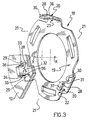
- Figure 3 is a partially-sectioned, perspective view of a detail of the disk of Figure 1.
-
- With reference to the appended drawings, a disk for a disk clutch for a motor vehicle is generally indicated 1.
- The disk 1 is intended for coupling a
flywheel 2 belonging to a engine of the motor vehicle for rotation with a shaft 3 belonging to a gearbox of the motor vehicle. - For this purpose, the disk 1, which has an axis X-X, comprises a hub 4 fixed for rotation with the shaft 3 and a
disk plate 5 which is provided withfriction material 6 and, when subjected to the action of apressure plate 7, is fixed for rotation with theflywheel 2. - The disk 1 comprises a main damper 8 having
springs 9 which can produce a large reaction torque, and a pre-damper 10 having springs 1 which can produce a gentle reaction torque which is developed, as is known, within the angular play of the main damper 8. - In particular, the disk 1 comprises a
disk flange 12 fixed to thedisk plate 5 and aflange 13 which is fixed to thedisk plate 5, for example, by means of spacer rods. Thedisk flange 12 and theflange 13 are spaced a predetermined distance apart so as to define between them aspace 14 in which thesprings 9 are housed. - The
space 14 also houses arespective hub flange 15 which is fixed for rotation with the hub 4, for example, by means of asplined coupling 15 having a predetermined angular play, and which cooperates with thesprings 9 to complete the damper 8. - The disk 1 according to the present invention comprises a substantially bell-shaped body, generally indicated 18, of axis X-X, having a
base 19 and askirt 20, and disposed in thespace 14 in a position between thedisk flange 12 and thehub flange 15 so that thebase 19 faces the hub flange and the skirt faces towards thedisk flange 12. - The
skirt 20 has three large, circumferentially uniformly-spacedopenings 21 for reducing its weight and terminates in afree rim 22 which in turn is restricted by the openings to three equally-spacedcircumferential portions 23. - The substantially bell-
shaped body 18 is closed onto thedisk flange 12 with thefree rim 22 in abutment with thedisk flange 12. Thebase 19 of the substantially bell-shaped body 18 is spaced from the disk flange and defines therewith aspace 24 in which the springs of the pre-damper 10 are housed. Thespace 24 also houses arespective hub flange 25 which is fixed for rotation with the hub 4, for example, by means of asplined coupling 26 having practically zero angular play. Thehub flange 25 cooperates with thesprings 11 to complete the pre-damper 10. - Fixing means for fixing the substantially bell-
shaped body 18 to thedisk flange 12 are generally indicated 27. - According to the invention, the fixing means 27 are constituted by three tabs, all indicated 28, which project axially from the
portions 23 of thefree rim 22, substantially in the centre of each portion, so that eachtab 28 defines in the respective portion two bearingregions 29 one on each side of the tab. - Between each bearing
region 29 and therespective tab 28 there is arelief 30 which ensures complete and perfect flatness of the bearing region itself. - Each
tab 28 has afirst portion 31 extending from thefree rim 22 through arespective slot 32 formed in thedisk flange 12 and havingsides 33 and an inwardly-facingend 34. - The
tabs 28 have respectiveouter faces 35 which are in locating engagement with theends 34 of theslots 32 so as to keep the substantially bell-shaped body 18 centred coaxially with thedisk flange 12. - Moreover, the
tabs 28 engage thesides 33 of theslots 32 with limited clearance so as to fix the substantially bell-shaped body 18 for rotation with thedisk flange 12. - Each
tab 28 has a radially outwardly-bent end portion 37 in engagement with thedisk flange 12. The substantially bell-shaped body 18 is thus restrained axially relative to thedisk flange 12 by the contact of the bearingregions 29 with one side of the disk flange and by the engagement of thebent end portion 37 of thetab 28 on the other side. - It should be noted that the substantially bell-
shaped body 18 is advantageously produced, complete with thetabs 28, by pressing of a steel sheet having a predetermined, limited thickness, for example, of 2mm. - The main advantage of the disk according to the present invention lies in its unusual structural and constructional simplicity which, bearing in mind that it is an item which is to be produced on a very large scale, is an extremely important advantage.
- A further advantage of the disk according to the present invention lies in its light weight.
- Finally, it is structurally strong so that it can be expected to be able to cope with a long operative life without problems.
- Naturally, in order to satisfy contingent and specific requirements, an expert in the art may apply to the above-described disk many modifications and variations all of which, however, are included within the scope of protection of the invention as defined by the following claims.
Claims (5)
- A disk (1) for a disk clutch for motor vehicles and the like, of the type comprising a disk flange (12) and a flange (13) fixed to the disk flange (12), a space (14) for housing springs (9) of a main damper (8) and a respective hub flange (15) being defined between the flanges, characterized in that a substantially bell-shaped body (18) being disposed in the space (14) between the disk flange (12) and the hub flange (15), the substantially bell-shaped body (18) is closed onto the disk flange (12) and defines with the disk flange (12) a space in which springs (11) of a pre-damper (10) and a respective hub flange (25) are housed, fixing means (27) being provided for fixing the substantially bell-shaped body (18) to the disk flange (12).
- A disk (1) according to Claim 1, characterized in that the substantially bell-shaped body (18) comprises a skirt (20) having a free rim (22) in abutment with the disk flange (12), and in that the fixing means (27) comprise tabs (28) projecting axially from the rim (22) of the skirt (20), each tab having a first portion (31) extending through a slot (32) formed in the disk flange (12) and a bent end portion (37) in engagement with the disk flange (12).
- A disk (1) according to Claim 2, characterized in that the first portions (31) of the tabs (28) have outer faces (35) in locating engagement in inwardly-facing ends (34) of the slots (32).
- A disk (1) according to Claim 3, characterized in that the end portions (37) of the tabs (28) are bent outwardly.
- A disk (1) according to Claim 4, characterized in that the substantially bell-shaped body (18) and the tabs (28) are formed in a single piece by pressing of a sheet of steel of predetermined limited thickness.
Priority Applications (2)
| Application Number | Priority Date | Filing Date | Title |
|---|---|---|---|
| DE69819296T DE69819296D1 (en) | 1998-01-29 | 1998-01-29 | Disk for a disk clutch |
| EP19980830040 EP0933554B1 (en) | 1998-01-29 | 1998-01-29 | A disk for a disk clutch |
Applications Claiming Priority (1)
| Application Number | Priority Date | Filing Date | Title |
|---|---|---|---|
| EP19980830040 EP0933554B1 (en) | 1998-01-29 | 1998-01-29 | A disk for a disk clutch |
Publications (2)
| Publication Number | Publication Date |
|---|---|
| EP0933554A1 EP0933554A1 (en) | 1999-08-04 |
| EP0933554B1 true EP0933554B1 (en) | 2003-10-29 |
Family
ID=8236527
Family Applications (1)
| Application Number | Title | Priority Date | Filing Date |
|---|---|---|---|
| EP19980830040 Expired - Lifetime EP0933554B1 (en) | 1998-01-29 | 1998-01-29 | A disk for a disk clutch |
Country Status (2)
| Country | Link |
|---|---|
| EP (1) | EP0933554B1 (en) |
| DE (1) | DE69819296D1 (en) |
Family Cites Families (4)
| Publication number | Priority date | Publication date | Assignee | Title |
|---|---|---|---|---|
| DE3242933A1 (en) * | 1982-11-20 | 1984-05-24 | LuK Lamellen und Kupplungsbau GmbH, 7580 Bühl | CLUTCH DISC |
| DE8501106U1 (en) * | 1985-01-18 | 1986-08-21 | Fichtel & Sachs Ag, 8720 Schweinfurt | Clutch disc with an additional friction stage in the pre-damper that can be controlled by a control disc |
| DE3542493C2 (en) * | 1985-11-30 | 1995-11-09 | Fichtel & Sachs Ag | Clutch disc for a motor vehicle friction clutch |
| FR2718208B1 (en) * | 1994-03-11 | 1996-06-07 | Valeo | Torsion pre-absorber, especially for a motor vehicle. |
-
1998
- 1998-01-29 EP EP19980830040 patent/EP0933554B1/en not_active Expired - Lifetime
- 1998-01-29 DE DE69819296T patent/DE69819296D1/en not_active Expired - Lifetime
Also Published As
| Publication number | Publication date |
|---|---|
| DE69819296D1 (en) | 2003-12-04 |
| EP0933554A1 (en) | 1999-08-04 |
Similar Documents
| Publication | Publication Date | Title |
|---|---|---|
| JP2833745B2 (en) | Clutch with damper type flywheel | |
| EP0797016B1 (en) | Multi-plate clutch mechanism | |
| US4222476A (en) | Torsion damping device for friction plate having a flexible center | |
| US4362230A (en) | Motor vehicle clutch mechanism | |
| US4222475A (en) | Torsion damping device, particularly for a motor vehicle clutch | |
| US4899862A (en) | Torsion damping device with a centring ring member | |
| JPS6084430A (en) | Clutch plate with torsional vibration damper at two step | |
| JPS61105322A (en) | Torsional vibration damper | |
| EP0696694B2 (en) | Torque absorbing disc | |
| US4270645A (en) | Torsion damping center and a clutch plate assembly having such a torsion damping center | |
| US5885160A (en) | Torsion damping device having circumferentially acting resilient members of different stiffness | |
| US4537580A (en) | Torsional damper device | |
| US6059662A (en) | Torsion predamping device | |
| EP0933554B1 (en) | A disk for a disk clutch | |
| US5641047A (en) | Clutch mechanism, notably for motor vehicles | |
| GB2092710A (en) | Torsionally damped clutch disc in the lock up clutch of an hydrodynamic coupling | |
| GB1569436A (en) | One-piece stamped clutch hub | |
| JPH0133861Y2 (en) | ||
| US5542516A (en) | Friction clutch for a transmission of a motor vehicle and a clutch plate for a friction clutch | |
| CA1082622A (en) | Two piece driven plate assembly | |
| GB2239508A (en) | Adjustable hysteresis damper | |
| US2189534A (en) | Friction clutch | |
| EP1046829B1 (en) | Clutch disc assembly with reinforcing plate welded thereto | |
| GB2247065A (en) | Clutch disk | |
| US20020017444A1 (en) | Clutch disk |
Legal Events
| Date | Code | Title | Description |
|---|---|---|---|
| PUAI | Public reference made under article 153(3) epc to a published international application that has entered the european phase |
Free format text: ORIGINAL CODE: 0009012 |
|
| AK | Designated contracting states |
Kind code of ref document: A1 Designated state(s): BE DE ES FI FR GB GR IT PT SE |
|
| AX | Request for extension of the european patent |
Free format text: AL;LT;LV;MK;RO;SI |
|
| 17P | Request for examination filed |
Effective date: 20000204 |
|
| AKX | Designation fees paid |
Free format text: BE DE ES FI FR GB GR IT PT SE |
|
| GRAH | Despatch of communication of intention to grant a patent |
Free format text: ORIGINAL CODE: EPIDOS IGRA |
|
| GRAH | Despatch of communication of intention to grant a patent |
Free format text: ORIGINAL CODE: EPIDOS IGRA |
|
| GRAA | (expected) grant |
Free format text: ORIGINAL CODE: 0009210 |
|
| AK | Designated contracting states |
Kind code of ref document: B1 Designated state(s): BE DE ES FI FR GB GR IT PT SE |
|
| PG25 | Lapsed in a contracting state [announced via postgrant information from national office to epo] |
Ref country code: FR Free format text: LAPSE BECAUSE OF FAILURE TO SUBMIT A TRANSLATION OF THE DESCRIPTION OR TO PAY THE FEE WITHIN THE PRESCRIBED TIME-LIMIT Effective date: 20031029 Ref country code: FI Free format text: LAPSE BECAUSE OF FAILURE TO SUBMIT A TRANSLATION OF THE DESCRIPTION OR TO PAY THE FEE WITHIN THE PRESCRIBED TIME-LIMIT Effective date: 20031029 Ref country code: ES Free format text: LAPSE BECAUSE OF FAILURE TO SUBMIT A TRANSLATION OF THE DESCRIPTION OR TO PAY THE FEE WITHIN THE PRESCRIBED TIME-LIMIT Effective date: 20031029 Ref country code: BE Free format text: LAPSE BECAUSE OF FAILURE TO SUBMIT A TRANSLATION OF THE DESCRIPTION OR TO PAY THE FEE WITHIN THE PRESCRIBED TIME-LIMIT Effective date: 20031029 |
|
| REG | Reference to a national code |
Ref country code: GB Ref legal event code: FG4D |
|
| REF | Corresponds to: |
Ref document number: 69819296 Country of ref document: DE Date of ref document: 20031204 Kind code of ref document: P |
|
| PG25 | Lapsed in a contracting state [announced via postgrant information from national office to epo] |
Ref country code: SE Free format text: LAPSE BECAUSE OF FAILURE TO SUBMIT A TRANSLATION OF THE DESCRIPTION OR TO PAY THE FEE WITHIN THE PRESCRIBED TIME-LIMIT Effective date: 20040129 Ref country code: GR Free format text: LAPSE BECAUSE OF FAILURE TO SUBMIT A TRANSLATION OF THE DESCRIPTION OR TO PAY THE FEE WITHIN THE PRESCRIBED TIME-LIMIT Effective date: 20040129 |
|
| PG25 | Lapsed in a contracting state [announced via postgrant information from national office to epo] |
Ref country code: DE Free format text: LAPSE BECAUSE OF FAILURE TO SUBMIT A TRANSLATION OF THE DESCRIPTION OR TO PAY THE FEE WITHIN THE PRESCRIBED TIME-LIMIT Effective date: 20040130 |
|
| PLBE | No opposition filed within time limit |
Free format text: ORIGINAL CODE: 0009261 |
|
| STAA | Information on the status of an ep patent application or granted ep patent |
Free format text: STATUS: NO OPPOSITION FILED WITHIN TIME LIMIT |
|
| 26N | No opposition filed |
Effective date: 20040730 |
|
| EN | Fr: translation not filed | ||
| PG25 | Lapsed in a contracting state [announced via postgrant information from national office to epo] |
Ref country code: PT Free format text: LAPSE BECAUSE OF NON-PAYMENT OF DUE FEES Effective date: 20040329 |
|
| PGFP | Annual fee paid to national office [announced via postgrant information from national office to epo] |
Ref country code: IT Payment date: 20070609 Year of fee payment: 10 Ref country code: GB Payment date: 20070717 Year of fee payment: 10 |
|
| GBPC | Gb: european patent ceased through non-payment of renewal fee |
Effective date: 20080129 |
|
| PG25 | Lapsed in a contracting state [announced via postgrant information from national office to epo] |
Ref country code: GB Free format text: LAPSE BECAUSE OF NON-PAYMENT OF DUE FEES Effective date: 20080129 |
|
| PG25 | Lapsed in a contracting state [announced via postgrant information from national office to epo] |
Ref country code: IT Free format text: LAPSE BECAUSE OF NON-PAYMENT OF DUE FEES Effective date: 20080129 |