EP0933516A2 - Gasification power generation process and equipment - Google Patents
Gasification power generation process and equipment Download PDFInfo
- Publication number
- EP0933516A2 EP0933516A2 EP98204216A EP98204216A EP0933516A2 EP 0933516 A2 EP0933516 A2 EP 0933516A2 EP 98204216 A EP98204216 A EP 98204216A EP 98204216 A EP98204216 A EP 98204216A EP 0933516 A2 EP0933516 A2 EP 0933516A2
- Authority
- EP
- European Patent Office
- Prior art keywords
- gas
- power generation
- gasification
- exhaust gas
- gas turbine
- Prior art date
- Legal status (The legal status is an assumption and is not a legal conclusion. Google has not performed a legal analysis and makes no representation as to the accuracy of the status listed.)
- Granted
Links
- 238000002309 gasification Methods 0.000 title claims abstract description 40
- 238000010248 power generation Methods 0.000 title claims abstract description 40
- 238000000034 method Methods 0.000 title claims abstract description 37
- 230000008569 process Effects 0.000 title claims abstract description 19
- 238000000746 purification Methods 0.000 claims abstract description 27
- 238000006477 desulfuration reaction Methods 0.000 claims abstract description 19
- 230000023556 desulfurization Effects 0.000 claims abstract description 19
- 239000000446 fuel Substances 0.000 claims abstract description 13
- 239000003245 coal Substances 0.000 claims abstract description 10
- 230000000694 effects Effects 0.000 claims abstract description 8
- 239000003208 petroleum Substances 0.000 claims abstract description 7
- 239000010440 gypsum Substances 0.000 claims description 22
- 229910052602 gypsum Inorganic materials 0.000 claims description 22
- 238000000576 coating method Methods 0.000 claims description 8
- 239000011248 coating agent Substances 0.000 claims description 7
- 239000000463 material Substances 0.000 claims description 6
- 238000005260 corrosion Methods 0.000 claims description 5
- 230000007797 corrosion Effects 0.000 claims description 5
- 239000012535 impurity Substances 0.000 claims description 4
- 238000010276 construction Methods 0.000 abstract description 19
- 230000006872 improvement Effects 0.000 abstract description 3
- 239000007789 gas Substances 0.000 description 162
- RAHZWNYVWXNFOC-UHFFFAOYSA-N Sulphur dioxide Chemical compound O=S=O RAHZWNYVWXNFOC-UHFFFAOYSA-N 0.000 description 38
- 239000000047 product Substances 0.000 description 34
- 239000012530 fluid Substances 0.000 description 24
- MWUXSHHQAYIFBG-UHFFFAOYSA-N nitrogen oxide Inorganic materials O=[N] MWUXSHHQAYIFBG-UHFFFAOYSA-N 0.000 description 18
- JJWKPURADFRFRB-UHFFFAOYSA-N carbonyl sulfide Chemical compound O=C=S JJWKPURADFRFRB-UHFFFAOYSA-N 0.000 description 16
- 239000007788 liquid Substances 0.000 description 15
- RWSOTUBLDIXVET-UHFFFAOYSA-N Dihydrogen sulfide Chemical compound S RWSOTUBLDIXVET-UHFFFAOYSA-N 0.000 description 13
- 229910000037 hydrogen sulfide Inorganic materials 0.000 description 13
- 238000007670 refining Methods 0.000 description 13
- 238000010521 absorption reaction Methods 0.000 description 11
- QGZKDVFQNNGYKY-UHFFFAOYSA-N Ammonia Chemical compound N QGZKDVFQNNGYKY-UHFFFAOYSA-N 0.000 description 9
- 239000000706 filtrate Substances 0.000 description 9
- 150000003464 sulfur compounds Chemical class 0.000 description 9
- 230000008929 regeneration Effects 0.000 description 7
- 238000011069 regeneration method Methods 0.000 description 7
- 238000002485 combustion reaction Methods 0.000 description 6
- 238000000926 separation method Methods 0.000 description 6
- 239000002002 slurry Substances 0.000 description 6
- 238000011144 upstream manufacturing Methods 0.000 description 6
- XLYOFNOQVPJJNP-UHFFFAOYSA-N water Substances O XLYOFNOQVPJJNP-UHFFFAOYSA-N 0.000 description 6
- 229940043430 calcium compound Drugs 0.000 description 5
- 150000001674 calcium compounds Chemical class 0.000 description 5
- 150000001805 chlorine compounds Chemical class 0.000 description 5
- VEXZGXHMUGYJMC-UHFFFAOYSA-N Hydrochloric acid Chemical compound Cl VEXZGXHMUGYJMC-UHFFFAOYSA-N 0.000 description 4
- MCMNRKCIXSYSNV-UHFFFAOYSA-N Zirconium dioxide Chemical compound O=[Zr]=O MCMNRKCIXSYSNV-UHFFFAOYSA-N 0.000 description 4
- 229910021529 ammonia Inorganic materials 0.000 description 4
- 239000006227 byproduct Substances 0.000 description 4
- 239000003795 chemical substances by application Substances 0.000 description 4
- 239000000295 fuel oil Substances 0.000 description 4
- IXCSERBJSXMMFS-UHFFFAOYSA-N hydrogen chloride Substances Cl.Cl IXCSERBJSXMMFS-UHFFFAOYSA-N 0.000 description 4
- 229910000041 hydrogen chloride Inorganic materials 0.000 description 4
- 239000010742 number 1 fuel oil Substances 0.000 description 4
- 239000002918 waste heat Substances 0.000 description 4
- UGFAIRIUMAVXCW-UHFFFAOYSA-N Carbon monoxide Chemical compound [O+]#[C-] UGFAIRIUMAVXCW-UHFFFAOYSA-N 0.000 description 3
- 239000002250 absorbent Substances 0.000 description 3
- 230000002745 absorbent Effects 0.000 description 3
- 239000003463 adsorbent Substances 0.000 description 3
- 238000001179 sorption measurement Methods 0.000 description 3
- LSNNMFCWUKXFEE-UHFFFAOYSA-N Sulfurous acid Chemical compound OS(O)=O LSNNMFCWUKXFEE-UHFFFAOYSA-N 0.000 description 2
- QVGXLLKOCUKJST-UHFFFAOYSA-N atomic oxygen Chemical compound [O] QVGXLLKOCUKJST-UHFFFAOYSA-N 0.000 description 2
- 238000007664 blowing Methods 0.000 description 2
- 238000006243 chemical reaction Methods 0.000 description 2
- 238000005229 chemical vapour deposition Methods 0.000 description 2
- 238000010586 diagram Methods 0.000 description 2
- 239000003546 flue gas Substances 0.000 description 2
- 238000010438 heat treatment Methods 0.000 description 2
- 239000003595 mist Substances 0.000 description 2
- 239000001301 oxygen Substances 0.000 description 2
- 229910052760 oxygen Inorganic materials 0.000 description 2
- 238000011084 recovery Methods 0.000 description 2
- 239000007787 solid Substances 0.000 description 2
- 239000007921 spray Substances 0.000 description 2
- ZAMOUSCENKQFHK-UHFFFAOYSA-N Chlorine atom Chemical compound [Cl] ZAMOUSCENKQFHK-UHFFFAOYSA-N 0.000 description 1
- UFHFLCQGNIYNRP-UHFFFAOYSA-N Hydrogen Chemical compound [H][H] UFHFLCQGNIYNRP-UHFFFAOYSA-N 0.000 description 1
- 235000019738 Limestone Nutrition 0.000 description 1
- -1 NO2) Chemical class 0.000 description 1
- NINIDFKCEFEMDL-UHFFFAOYSA-N Sulfur Chemical compound [S] NINIDFKCEFEMDL-UHFFFAOYSA-N 0.000 description 1
- UCKMPCXJQFINFW-UHFFFAOYSA-N Sulphide Chemical compound [S-2] UCKMPCXJQFINFW-UHFFFAOYSA-N 0.000 description 1
- 238000013019 agitation Methods 0.000 description 1
- 230000008901 benefit Effects 0.000 description 1
- ZOMBKNNSYQHRCA-UHFFFAOYSA-J calcium sulfate hemihydrate Chemical compound O.[Ca+2].[Ca+2].[O-]S([O-])(=O)=O.[O-]S([O-])(=O)=O ZOMBKNNSYQHRCA-UHFFFAOYSA-J 0.000 description 1
- 229910002091 carbon monoxide Inorganic materials 0.000 description 1
- 239000003054 catalyst Substances 0.000 description 1
- 230000003197 catalytic effect Effects 0.000 description 1
- 238000005524 ceramic coating Methods 0.000 description 1
- 229910010293 ceramic material Inorganic materials 0.000 description 1
- 239000000460 chlorine Substances 0.000 description 1
- 229910052801 chlorine Inorganic materials 0.000 description 1
- 230000018109 developmental process Effects 0.000 description 1
- 150000004683 dihydrates Chemical class 0.000 description 1
- 238000007599 discharging Methods 0.000 description 1
- 239000006185 dispersion Substances 0.000 description 1
- 238000001035 drying Methods 0.000 description 1
- 238000003912 environmental pollution Methods 0.000 description 1
- 239000001257 hydrogen Substances 0.000 description 1
- 229910052739 hydrogen Inorganic materials 0.000 description 1
- 239000008235 industrial water Substances 0.000 description 1
- 239000006028 limestone Substances 0.000 description 1
- 150000002681 magnesium compounds Chemical class 0.000 description 1
- VTHJTEIRLNZDEV-UHFFFAOYSA-L magnesium dihydroxide Chemical compound [OH-].[OH-].[Mg+2] VTHJTEIRLNZDEV-UHFFFAOYSA-L 0.000 description 1
- 229910001862 magnesium hydroxide Inorganic materials 0.000 description 1
- 239000000347 magnesium hydroxide Substances 0.000 description 1
- 229910052751 metal Inorganic materials 0.000 description 1
- 239000002184 metal Substances 0.000 description 1
- 238000006386 neutralization reaction Methods 0.000 description 1
- 229910017464 nitrogen compound Inorganic materials 0.000 description 1
- 150000002830 nitrogen compounds Chemical class 0.000 description 1
- 229910000069 nitrogen hydride Inorganic materials 0.000 description 1
- 238000001556 precipitation Methods 0.000 description 1
- 239000002994 raw material Substances 0.000 description 1
- 230000009467 reduction Effects 0.000 description 1
- 238000011946 reduction process Methods 0.000 description 1
- 230000004044 response Effects 0.000 description 1
- 230000000630 rising effect Effects 0.000 description 1
- 238000005201 scrubbing Methods 0.000 description 1
- 238000004544 sputter deposition Methods 0.000 description 1
- 229910052717 sulfur Inorganic materials 0.000 description 1
- 239000011593 sulfur Substances 0.000 description 1
- 238000007751 thermal spraying Methods 0.000 description 1
- 239000002351 wastewater Substances 0.000 description 1
- 238000004065 wastewater treatment Methods 0.000 description 1
Images

Classifications
-
- F—MECHANICAL ENGINEERING; LIGHTING; HEATING; WEAPONS; BLASTING
- F02—COMBUSTION ENGINES; HOT-GAS OR COMBUSTION-PRODUCT ENGINE PLANTS
- F02C—GAS-TURBINE PLANTS; AIR INTAKES FOR JET-PROPULSION PLANTS; CONTROLLING FUEL SUPPLY IN AIR-BREATHING JET-PROPULSION PLANTS
- F02C3/00—Gas-turbine plants characterised by the use of combustion products as the working fluid
- F02C3/20—Gas-turbine plants characterised by the use of combustion products as the working fluid using a special fuel, oxidant, or dilution fluid to generate the combustion products
- F02C3/26—Gas-turbine plants characterised by the use of combustion products as the working fluid using a special fuel, oxidant, or dilution fluid to generate the combustion products the fuel or oxidant being solid or pulverulent, e.g. in slurry or suspension
- F02C3/28—Gas-turbine plants characterised by the use of combustion products as the working fluid using a special fuel, oxidant, or dilution fluid to generate the combustion products the fuel or oxidant being solid or pulverulent, e.g. in slurry or suspension using a separate gas producer for gasifying the fuel before combustion
-
- B—PERFORMING OPERATIONS; TRANSPORTING
- B01—PHYSICAL OR CHEMICAL PROCESSES OR APPARATUS IN GENERAL
- B01D—SEPARATION
- B01D53/00—Separation of gases or vapours; Recovering vapours of volatile solvents from gases; Chemical or biological purification of waste gases, e.g. engine exhaust gases, smoke, fumes, flue gases, aerosols
- B01D53/34—Chemical or biological purification of waste gases
- B01D53/46—Removing components of defined structure
- B01D53/48—Sulfur compounds
-
- Y—GENERAL TAGGING OF NEW TECHNOLOGICAL DEVELOPMENTS; GENERAL TAGGING OF CROSS-SECTIONAL TECHNOLOGIES SPANNING OVER SEVERAL SECTIONS OF THE IPC; TECHNICAL SUBJECTS COVERED BY FORMER USPC CROSS-REFERENCE ART COLLECTIONS [XRACs] AND DIGESTS
- Y02—TECHNOLOGIES OR APPLICATIONS FOR MITIGATION OR ADAPTATION AGAINST CLIMATE CHANGE
- Y02E—REDUCTION OF GREENHOUSE GAS [GHG] EMISSIONS, RELATED TO ENERGY GENERATION, TRANSMISSION OR DISTRIBUTION
- Y02E20/00—Combustion technologies with mitigation potential
- Y02E20/16—Combined cycle power plant [CCPP], or combined cycle gas turbine [CCGT]
- Y02E20/18—Integrated gasification combined cycle [IGCC], e.g. combined with carbon capture and storage [CCS]
Definitions
- This invention relates to gasification power generation techniques such as coal gasification power generation. More particularly, it relates to a technique which enables the purification of gas to be carried out by very simple and economical equipment construction.
- product gases obtained by the gasification of coal or heavy oils contain, for example, several hundred to several thousand parts per million (ppm) of sulfur compounds (chiefly hydrogen sulfide). It has conventionally been believed that such harmful components need to be removed at as upstream a position as possible in order to prevent environmental pollution or protect equipment against corrosion.
- ppm parts per million
- an oxide of a metal e.g., Fe
- sulfur compounds contained in a gas are adsorbed by the adsorbent and removed in the form of a sulfide
- the adsorbent having reduced adsorption capacity is regenerated by roasting it with an oxygen-containing gas
- the regeneration gas containing sulfur dioxide formed by the roasting reaction is introduced into a reactor where it is brought into gas-liquid contact with a calcium compound-containing slurry to effect the absorption of sulfur dioxide and the precipitation of gypsum formed as a by-product.
- sulfur compounds contained in a product gas are removed bringing the product gas into gas-liquid contact with a sulfur compound-absorbing fluid, and the absorbing fluid having absorbed sulfur compounds is heated to release a regeneration gas containing sulfur compounds. Then, this regeneration gas is burned to convert it into flue gas containing sulfur dioxide, and sulfur dioxide present in this flue gas is again absorbed by the wet lime-gypsum method to form gypsum.
- Gasification power generation employing any of the above-described conventional gas refining techniques has the advantage that the exhaust gas discharged from power generation equipment can be highly purified and, moreover, useful gypsum can be yielded.
- the dry gas refining process has had the disadvantage that high purification performance (e.g., a high degree of desulfurization) cannot be achieved, while the wet gas refining process has had the disadvantage that the gas is cooled by contact with the absorbing fluid during gas refining to cause a reduction in thermal efficiency.
- high purification performance e.g., a high degree of desulfurization
- An object of the present invention is to provide a gasification power generation process or gasification power generation equipment which is more suitable for practical use from an economic point of view in that a high degree of exhaust gas purification and a marked improvement in thermal efficiency can be achieved and, moreover, the construction of the equipment for carrying out a gas purification treatment including at least desulfurization can be highly simplified.
- the above object is accomplished by providing a gasification power generation process wherein a product gas obtained by the gasification of coal or petroleum is used as the fuel of a gas turbine for electric power generation, the process comprising the steps of dedusting the product gas, introducing the product gas directly into the gas turbine as the fuel thereof to effect electric power generation, and subjecting the exhaust gas discharged from the gas turbine to a gas purification treatment including at least desulfurization.
- the gas purification treatment is an exhaust gas treatment based on the wet lime-gypsum method.
- gasification power generation equipment comprising a gasification furnace for gasifying coal or petroleum, dedusting means for dedusting the product gas obtained from the gasification furnace, a gas turbine for electric power generation into which the product gas leaving the dedusting means is directly introduced as the fuel thereof, and gas purification means for subjecting the exhaust gas discharged from the gas turbine to a gas purification treatment including at least desulfurization.
- the material surfaces of the gas turbine which come into contact with the product gas and the exhaust gas are protected with a coating having corrosion resistance to at least impurities contained in the product gas.
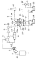
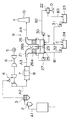
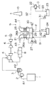
- FIG. 1 is a flow diagram showing the construction of gasification power generation equipment in accordance with one embodiment of the present invention.
- FIG. 1 is a flow diagram illustrating gasification power generation equipment for practicing one embodiment of the present invention. Since the present invention is characterized by equipment construction for gas refining treatment and the like, the detailed construction of a power generation system itself (for example, the construction of a steam cycle) is not shown.
- coal for example, is gasified in a gasification furnace 1 by using air as the gasifying agent.
- product gas A1 consisting essentially of carbon monoxide and hydrogen is generated.
- Such product gas A1 obtained by using coal as the raw material and air as the gasifying agent usually contains about 1,000 to 1,500 ppm of H 2 S (hydrogen sulfide) and about 100 ppm of COS (carbonyl sulfide), as well as about 1,000 to 1,500 ppm of NH 3 (ammonia) and about 100 ppm of HCl (hydrogen chloride).
- product gas A1 just behind the outlet of the furnace typically has a temperature of 1,000 to 2,000°C, it is usually cooled, for example, to about 350°C as a result of heat recovery by a steam heater (not shown) installed on the downstream side of the furnace. Its pressure is, for example, about 26 ata.
- This product gas A1 is dedusted by dedusting means such as a cyclone 2 and a porous filter 3. Thereafter, as illustrated in FIG. 1, product gas A1 is directly introduced into a gas turbine 4 as the fuel thereof.
- product gas A1 is burned and its energy is utilized to drive a generator 5 and thereby effect electric power generation.
- the electric power generation system in accordance with this embodiment is a so-called combined power generation system equipped with both gas turbine 4 and steam turbine 6.
- generator 5 is driven by the output of gas turbine 4 and the output of steam turbine 6.
- the high-temperature and high-pressure steam generated and heated by the previously described steam heater and waste heat boilers 7 which will be described later is used to drive steam turbine 6.
- the turbine blades and other components of gas turbine 4 are protected with a coating for improving their heat resistance and corrosion resistance, so that gas turbine 4 can be operated without any problem even if the above-described harmful components (e.g., hydrogen sulfide and hydrogen chloride) are contained in the fuel.
- the coating material include zirconia and other ceramic materials.
- Useful coating methods include ceramic coating by thermal spraying, chemical vapor deposition (CVD) and sputtering.
- CVD chemical vapor deposition
- sputtering there may be employed a method which comprises applying a coating material to the surface to be protected and drying it to form, for example, a zirconia coating.
- exhaust gas A2 resulting from the combustion of product gas A1 in gas turbine 4 is introduced into waste heat boilers 7 and a denitrator 8 (gas purification means).
- Denitrator 8 which is installed for the purpose of decomposing nitrogen oxides present in exhaust gas A2, functions to decompose nitrogen oxides with the aid of a catalyst according to the catalytic ammonia reduction process.
- Waste heat boilers 7 are boilers disposed before and behind denitrator 8 to recover heat from exhaust gas A2 and to generate or heat stream to be supplied to a steam turbine 6 for purposes of cogeneration. In order to optimize the gas temperature in denitrator 8, the heat recovery sections of waste heat boilers 7 are installed before and behind denitrator 8.
- exhaust gas A3 resulting from the denitration of exhaust gas A2 is introduced into an exhaust gas treating apparatus 9 (gas purification means) based on the wet lime-gypsum method, where exhaust gas A3 is chiefly subjected to a desulfurization treatment (i.e., the absorption of sulfur dioxide).
- Exhaust gas A4 resulting from the purification of exhaust gas A3 in exhaust gas treating apparatus 9 is conducted, for example, to a stack and discharged into the atmosphere. It goes without saying that, for example, a part of the purified exhaust gas A4 may be recycled to gasification furnace 1 for use as a part of the gasifying agent.
- exhaust gas treating apparatus 9 has the same construction as desulfurizers for use in conventional thermal electric power plants.
- exhaust gas treating apparatus 9 is constructed as described below with reference to FIG. 1.
- This apparatus 9 comprises an absorption tower 21 where exhaust gas A3 containing a high concentration of sulfur dioxide is brought into gas-liquid contact with an absorbing fluid B1 comprising a slurry containing a calcium compound as the absorbent and then discharged therefrom as purified exhaust gas A4, and where oxidising air C is blown into the absorbing fluid having sulfur dioxide absorbed therein in the form of a large number of fine bubbles so as to oxidize sulfurous acid present in the absorbing fluid and thereby form gypsum; a solid-liquid separation means (e.g., centrifugal separator) 22 for effecting the solid-liquid separation of a slurry B2 (gypsum slurry) withdrawn from absorption tower 21; a filtrate pit 23 for storing the filtrate B3 yielded in solid-liquid separation means 22; and an absorbing fluid pit 24 for preparing absorbing fluid B1.
- a solid-liquid separation means e.g., centrifugal separator 22 for effecting the solid-liquid separation of a
- this apparatus 9 may further be equipped with a gypsum heater (e.g., combustion furnace) for heating the solid matter D (gypsum dihydrate cake) separated in solid-liquid separation means 22 to a temperature of about 120 to 150°C and thereby converting it into gypsum hemihydrate.
- a gypsum heater e.g., combustion furnace
- absorption tower 21 has a tank 25 formed at the bottom thereof for holding absorbing fluid B1, and two tower bodies 26a and 26b juxtaposed above this single tank 25.
- the absorbing fluid within tank 25 is sucked up by means of a circulating pump 27, injected upward in the form of liquid columns from spray nozzles installed in each tower body, and thereby brought into efficient gas-liquid contact with exhaust gas A3.
- tower body 26a is a so-called parallel-flow type gas-liquid contact tower
- tower body 26b is a so-called counterflow type gas-liquid contact tower.
- exhaust gas A3 to be treated is introduced into the top of tower body 26a, then introduced into the lower part of tower body 26b by way of the space above tank 25, and finally discharged from the top of tower body 26b.
- absorption tower 21 is not limited to the above-described construction, but may be otherwise constructed, for example, so as to have a plurality of additional tower bodies.
- a mist eliminator (not shown) is usually installed in an outlet duct 28 for the treated exhaust gas A4, so that any entrained mist is removed from exhaust gas A4 and returned to tank 25.
- Tank 25 is equipped with a rotating-arm air sparger 29 for blowing air C in the form of fine bubbles and for agitating the whole slurry within tank 25.
- a rotating-arm air sparger 29 for blowing air C in the form of fine bubbles and for agitating the whole slurry within tank 25.
- the absorbing fluid containing a high concentration of gypsum i.e., slurry B2
- slurry B2 a high concentration of gypsum
- a solid-liquid separator 22 where it is subjected to solid-liquid separation and its solid component is recovered as gypsum D.
- the filtrate resulting from the aforesaid solid-liquid separation i.e., filtrate B3 is temporarily stored in filtrate pit 23, suitably sucked up by means of a pump 31, and conveyed to tank 25 or absorbing fluid pit 24. In any event, filtrate B3 is finally returned and reused in to tank 25.
- absorbing fluid pit 24 a calcium compound E (e.g., limestone) supplied from a silo (not shown) is mixed and stirred with a corresponding amount of filtrate B3, so that absorbing fluid B1 having a predetermined concentration is prepared.
- Absorbing fluid B1 within this absorbing fluid pit 24 is conveyed to tank 25 by means of a pump 32 while its flow rate is controlled in response, for example, to the detected value of the sulfur dioxide concentration in exhaust gas A3 which is the gas being treated.
- make-up water F (e.g., industrial water) is supplied to tank 25, for example, in such a way that the fluid level within tank 25 will be kept within predetermined limits.
- a suitable measure is taken to prevent impurities (e.g., chlorine) absorbed into the absorbing fluid together with sulfur dioxide from accumulating in the liquid component of the circulating absorbing fluid. This may be accomplished, for example, by withdrawing a portion of the filtrate within the filtrate pit, subjecting it to a waste water treatment, and then discharging it out of the system or reusing it.
- impurities e.g., chlorine
- the same construction may preferably be employed in this embodiment.
- product gas A1 leaving gasification furnace 1 is dedusted and then introduced directly into gas turbine 4 where it is used as the fuel of gas turbine 4. Consequently, most of the hydrogen sulfide and carbonyl sulfide contained in product gas A1 are converted into sulfur dioxide in this gas turbine 4, for example, according to the combustion reactions represented by the following equations (1) and (2).
- the resulting sulfur dioxide is discharged while being contained in exhaust gas A2 leaving gas turbine 4. H 2 S + 3/2O 2 ⁇ SO 2 + H 2 O COS + 3/2O 2 ⁇ SO 2 + CO 2
- exhaust gas A2 further contains trace amounts of chlorine compounds formed from hydrogen chloride contained in product gas A1. 2NH 3 + 7/2O 2 ⁇ 2NO 2 + 3H 2 O
- the nitrogen oxides are decomposed and removed in denitrator 8.
- the sulfur dioxide and the trace amounts of chlorine compounds are absorbed into the absorbing fluid in exhaust gas treating apparatus 9.
- the absorbed sulfur compound is utilized to form gypsum as a by-product, and the absorbed chlorine compounds are discharged out of the system while being contained, for example, in waste water from exhaust gas treating apparatus 9.
- this embodiment is characterized in that the entire gas purification treatment, except dedusting, is carried out on the downstream side of the gas turbine and in that the gas purification treatment including desulfurization comprises an exhaust gas treatment based on the wet lime-gypsum method. Consequently, this embodiment has the following excellent effects from a practical point of view.
- the exhaust gas treatment for effecting desulfurization and the like is not limited to the above-described one based on the lime-gypsum method, but there may be employed other methods including, for example, the so-called magnesium hydroxide method using a magnesium compound as the absorbent for sulfur dioxide.
- the absorption tower of the exhaust gas treating apparatus is not limited to a liquid-column type absorption tower, but there may be used various types of absorption towers including spray towers, packed grid towers and gas dispersion type absorption towers.
- the method of gasification may be such that, for example, oxygen is used as the gasifying agent.
- the treatment for denitrating exhaust gas from the gas turbine and the denitrator used for this purpose are not always necessary.
- the concentration of nitrogen oxides in the exhaust gas is very low owing, for example, to the properties of coal and the like or the type of the gasification furnace or gas turbine, the aforesaid denitration treatment is not required as a matter of course.
- a gas produced in a gasification furnace is dedusted and then introduced directly into a gas turbine as the fuel thereof to effect electric power generation, and the exhaust gas discharged from the gas turbine is subjected to a gas purification treatment including at least desulfurization. That is, by changing the conventional conception in which a product gas is previously purified on the upstream side of a gas turbine, a product gas having undergone a dedusting treatment alone is burned in a gas turbine to effect electric power generation, and the exhaust gas discharged from the gas turbine is subjected to a gas purification treatment.
- the equipment construction in accordance with the present invention is very simple because, in order to carry out the gas refining treatment (or gas purification treatment) except dedusting, a treating apparatus similar in construction to, for example, common desulfurizers which have been employed in the prior art may only be installed on the downstream side of the gas turbine. Moreover, in spite of such simple equipment construction, harmful components including at least sulfur compounds can be removed from the exhaust gas, so that highly purified exhaust gas is obtained as a result of the treatment and, when the wet lime-gypsum method is employed, useful gypsum is formed as a by-product.
- the present invention is advantageous in that, since the product gas is not brought into contact with an absorbing fluid before being introduced into a gas turbine, high thermal efficiency can be achieved. Thus, electric power can be efficiently generated by using valuable resources. Furthermore, since the equipment for effecting gas refining may be composed entirely of apparatus (e.g., a common desulfurizer and the like) which have produced satisfactory results in common existing thermal electric power plants involving no gasification, the reliability of the equipment is particularly enhanced.
- apparatus e.g., a common desulfurizer and the like
- the gas turbine when the material surfaces of the gas turbine which come into contact with the product gas and the exhaust gas are protected with a coating having corrosion resistance to at least impurities contained in the product gas, the gas turbine can be operated for a long period of time and the service life of the equipment can be easily lengthened to a practically sufficient extent, in spite of the equipment construction in which the product gas is not purified on the upstream side of the gas turbine.
Abstract
Description
- This invention relates to gasification power generation techniques such as coal gasification power generation. More particularly, it relates to a technique which enables the purification of gas to be carried out by very simple and economical equipment construction.
- In recent years, the diversification of fuels is being advocated because of the exhaustion and rising cost of petroleum resources, and the development of techniques for utilizing coal and heavy oils is being promoted. As an example, attention is being paid to techniques for gasifying coal and heavy oils to utilize them for electric power generation. Moreover, since electric power generation using gases obtained by the gasification of coal and heavy oils is more efficient than conventional thermal electric power generation using coal and petroleum, such techniques are also attracting attention from the viewpoint of effective utilization of finite resources.
- However, product gases obtained by the gasification of coal or heavy oils contain, for example, several hundred to several thousand parts per million (ppm) of sulfur compounds (chiefly hydrogen sulfide). It has conventionally been believed that such harmful components need to be removed at as upstream a position as possible in order to prevent environmental pollution or protect equipment against corrosion.
- Among conventionally known processes for removing such sulfur compounds, the dry gas refining process described, for example, in Japanese Patent Provisional Publication Nos. 63-123801 and 1-254226 is advantageous from the viewpoint of thermal economy.
- According to this process, an oxide of a metal (e.g., Fe) is used as an adsorbent, sulfur compounds contained in a gas are adsorbed by the adsorbent and removed in the form of a sulfide, the adsorbent having reduced adsorption capacity is regenerated by roasting it with an oxygen-containing gas, and the regeneration gas containing sulfur dioxide formed by the roasting reaction is introduced into a reactor where it is brought into gas-liquid contact with a calcium compound-containing slurry to effect the absorption of sulfur dioxide and the precipitation of gypsum formed as a by-product.
- On the other hand, the wet gas refining process described, for example, in Japanese Patent Provisional Publication No. 6-293888 is known to be advantageous from the viewpoint of purification performance.
- According to this process, sulfur compounds contained in a product gas are removed bringing the product gas into gas-liquid contact with a sulfur compound-absorbing fluid, and the absorbing fluid having absorbed sulfur compounds is heated to release a regeneration gas containing sulfur compounds. Then, this regeneration gas is burned to convert it into flue gas containing sulfur dioxide, and sulfur dioxide present in this flue gas is again absorbed by the wet lime-gypsum method to form gypsum.
- Gasification power generation employing any of the above-described conventional gas refining techniques has the advantage that the exhaust gas discharged from power generation equipment can be highly purified and, moreover, useful gypsum can be yielded.
- However, since gas refining equipment of complicated construction is required and this places a limit in reducing the space and cost requirements of the electric power plant, further improvements have been strongly desired for the purpose of carrying out gasification power generation more economically.
- Moreover, the dry gas refining process has had the disadvantage that high purification performance (e.g., a high degree of desulfurization) cannot be achieved, while the wet gas refining process has had the disadvantage that the gas is cooled by contact with the absorbing fluid during gas refining to cause a reduction in thermal efficiency.
- An object of the present invention is to provide a gasification power generation process or gasification power generation equipment which is more suitable for practical use from an economic point of view in that a high degree of exhaust gas purification and a marked improvement in thermal efficiency can be achieved and, moreover, the construction of the equipment for carrying out a gas purification treatment including at least desulfurization can be highly simplified.
- According to a first aspect of the present invention, the above object is accomplished by providing a gasification power generation process wherein a product gas obtained by the gasification of coal or petroleum is used as the fuel of a gas turbine for electric power generation, the process comprising the steps of dedusting the product gas, introducing the product gas directly into the gas turbine as the fuel thereof to effect electric power generation, and subjecting the exhaust gas discharged from the gas turbine to a gas purification treatment including at least desulfurization.
- In this gasification power generation process, it is preferable that the gas purification treatment is an exhaust gas treatment based on the wet lime-gypsum method.
- According to a second aspect of the present invention, there is provided gasification power generation equipment comprising a gasification furnace for gasifying coal or petroleum, dedusting means for dedusting the product gas obtained from the gasification furnace, a gas turbine for electric power generation into which the product gas leaving the dedusting means is directly introduced as the fuel thereof, and gas purification means for subjecting the exhaust gas discharged from the gas turbine to a gas purification treatment including at least desulfurization.
- In this gasification power generation equipment, it is preferable that the material surfaces of the gas turbine which come into contact with the product gas and the exhaust gas are protected with a coating having corrosion resistance to at least impurities contained in the product gas.
- FIG. 1 is a flow diagram showing the construction of gasification power generation equipment in accordance with one embodiment of the present invention.
- The reference characters given in this figure are defined as follows: 1, gasification furnace; 2, cyclone (dedusting means); 3, porous filter (dedusting means); 4, gas turbine; 8, denitrator (gas purification means); 9, exhaust gas treating apparatus (gas purification means); A1, product gas; A2 to A4, exhaust gas; B1, absorbing fluid; C, air; D, gypsum; E, absorbent (calcium compound).
- One embodiment of the present invention will be described hereinbelow with reference to the accompanying drawings.
- FIG. 1 is a flow diagram illustrating gasification power generation equipment for practicing one embodiment of the present invention. Since the present invention is characterized by equipment construction for gas refining treatment and the like, the detailed construction of a power generation system itself (for example, the construction of a steam cycle) is not shown.
- First of all, coal, for example, is gasified in a gasification furnace 1 by using air as the gasifying agent. Thus, product gas A1 consisting essentially of carbon monoxide and hydrogen is generated.
- Such product gas A1 obtained by using coal as the raw material and air as the gasifying agent usually contains about 1,000 to 1,500 ppm of H2S (hydrogen sulfide) and about 100 ppm of COS (carbonyl sulfide), as well as about 1,000 to 1,500 ppm of NH3 (ammonia) and about 100 ppm of HCl (hydrogen chloride).
- Moreover, although product gas A1 just behind the outlet of the furnace typically has a temperature of 1,000 to 2,000°C, it is usually cooled, for example, to about 350°C as a result of heat recovery by a steam heater (not shown) installed on the downstream side of the furnace. Its pressure is, for example, about 26 ata.
- This product gas A1 is dedusted by dedusting means such as a
cyclone 2 and aporous filter 3. Thereafter, as illustrated in FIG. 1, product gas A1 is directly introduced into agas turbine 4 as the fuel thereof. - In
gas turbine 4, product gas A1 is burned and its energy is utilized to drive agenerator 5 and thereby effect electric power generation. - The electric power generation system in accordance with this embodiment is a so-called combined power generation system equipped with both
gas turbine 4 andsteam turbine 6. In the embodiment illustrated in FIG. 1,generator 5 is driven by the output ofgas turbine 4 and the output ofsteam turbine 6. Moreover, the high-temperature and high-pressure steam generated and heated by the previously described steam heater andwaste heat boilers 7 which will be described later is used to drivesteam turbine 6. - The turbine blades and other components of
gas turbine 4 are protected with a coating for improving their heat resistance and corrosion resistance, so thatgas turbine 4 can be operated without any problem even if the above-described harmful components (e.g., hydrogen sulfide and hydrogen chloride) are contained in the fuel. Useful examples of the coating material include zirconia and other ceramic materials. Useful coating methods include ceramic coating by thermal spraying, chemical vapor deposition (CVD) and sputtering. Moreover, there may be employed a method which comprises applying a coating material to the surface to be protected and drying it to form, for example, a zirconia coating. - Next, exhaust gas A2 resulting from the combustion of product gas A1 in
gas turbine 4 is introduced intowaste heat boilers 7 and a denitrator 8 (gas purification means). -
Denitrator 8, which is installed for the purpose of decomposing nitrogen oxides present in exhaust gas A2, functions to decompose nitrogen oxides with the aid of a catalyst according to the catalytic ammonia reduction process.Waste heat boilers 7 are boilers disposed before and behinddenitrator 8 to recover heat from exhaust gas A2 and to generate or heat stream to be supplied to asteam turbine 6 for purposes of cogeneration. In order to optimize the gas temperature indenitrator 8, the heat recovery sections ofwaste heat boilers 7 are installed before and behinddenitrator 8. - Next, exhaust gas A3 resulting from the denitration of exhaust gas A2 is introduced into an exhaust gas treating apparatus 9 (gas purification means) based on the wet lime-gypsum method, where exhaust gas A3 is chiefly subjected to a desulfurization treatment (i.e., the absorption of sulfur dioxide). Exhaust gas A4 resulting from the purification of exhaust gas A3 in exhaust
gas treating apparatus 9 is conducted, for example, to a stack and discharged into the atmosphere. It goes without saying that, for example, a part of the purified exhaust gas A4 may be recycled to gasification furnace 1 for use as a part of the gasifying agent. - In this embodiment, exhaust
gas treating apparatus 9 has the same construction as desulfurizers for use in conventional thermal electric power plants. By way of example, exhaustgas treating apparatus 9 is constructed as described below with reference to FIG. 1. - This
apparatus 9 comprises anabsorption tower 21 where exhaust gas A3 containing a high concentration of sulfur dioxide is brought into gas-liquid contact with an absorbing fluid B1 comprising a slurry containing a calcium compound as the absorbent and then discharged therefrom as purified exhaust gas A4, and where oxidising air C is blown into the absorbing fluid having sulfur dioxide absorbed therein in the form of a large number of fine bubbles so as to oxidize sulfurous acid present in the absorbing fluid and thereby form gypsum; a solid-liquid separation means (e.g., centrifugal separator) 22 for effecting the solid-liquid separation of a slurry B2 (gypsum slurry) withdrawn fromabsorption tower 21; afiltrate pit 23 for storing the filtrate B3 yielded in solid-liquid separation means 22; and an absorbingfluid pit 24 for preparing absorbing fluid B1. - Moreover, this
apparatus 9 may further be equipped with a gypsum heater (e.g., combustion furnace) for heating the solid matter D (gypsum dihydrate cake) separated in solid-liquid separation means 22 to a temperature of about 120 to 150°C and thereby converting it into gypsum hemihydrate. - In this embodiment,
absorption tower 21 has atank 25 formed at the bottom thereof for holding absorbing fluid B1, and twotower bodies single tank 25. The absorbing fluid withintank 25 is sucked up by means of a circulatingpump 27, injected upward in the form of liquid columns from spray nozzles installed in each tower body, and thereby brought into efficient gas-liquid contact with exhaust gas A3. - Of the two tower bodies,
tower body 26a is a so-called parallel-flow type gas-liquid contact tower, andtower body 26b is a so-called counterflow type gas-liquid contact tower. In this case, exhaust gas A3 to be treated is introduced into the top oftower body 26a, then introduced into the lower part oftower body 26b by way of the space abovetank 25, and finally discharged from the top oftower body 26b. - It is to be understood that
absorption tower 21 is not limited to the above-described construction, but may be otherwise constructed, for example, so as to have a plurality of additional tower bodies. - Moreover, a mist eliminator (not shown) is usually installed in an
outlet duct 28 for the treated exhaust gas A4, so that any entrained mist is removed from exhaust gas A4 and returned totank 25. - Tank 25 is equipped with a rotating-
arm air sparger 29 for blowing air C in the form of fine bubbles and for agitating the whole slurry withintank 25. Thus, the absorbing fluid flowing down through both tower bodies while absorbing sulfur dioxide is brought into efficient contact with the air blown intotank 25, so that the absorbed sulfurous acid is almost totally oxidized and then undergoes a neutralization reaction with the calcium compound to form highly pure gypsum. Alternatively, a means for blowing in air C (e.g., a stationary air sparger or rotary atomizer) may be installed withintank 25 separately from an agitation means. - In a steady state, the absorbing fluid containing a high concentration of gypsum (i.e., slurry B2) is withdrawn from
tank 25 by means of apump 30, and transferred to a solid-liquid separator 22 where it is subjected to solid-liquid separation and its solid component is recovered as gypsum D. On the other hand, the filtrate resulting from the aforesaid solid-liquid separation (i.e., filtrate B3) is temporarily stored infiltrate pit 23, suitably sucked up by means of apump 31, and conveyed to tank 25 or absorbingfluid pit 24. In any event, filtrate B3 is finally returned and reused in totank 25. - In absorbing
fluid pit 24, a calcium compound E (e.g., limestone) supplied from a silo (not shown) is mixed and stirred with a corresponding amount of filtrate B3, so that absorbing fluid B1 having a predetermined concentration is prepared. Absorbing fluid B1 within this absorbingfluid pit 24 is conveyed totank 25 by means of apump 32 while its flow rate is controlled in response, for example, to the detected value of the sulfur dioxide concentration in exhaust gas A3 which is the gas being treated. - Moreover, in order to make up for the water evaporated in
absorption tower 21 and carried away by the exhaust gas in the form of water vapor, and the water discharged out of the system as water contained in or attached to gypsum D, make-up water F (e.g., industrial water) is supplied totank 25, for example, in such a way that the fluid level withintank 25 will be kept within predetermined limits. - In common desulfurizers attached to typical thermal electric power plants and the like, a suitable measure is taken to prevent impurities (e.g., chlorine) absorbed into the absorbing fluid together with sulfur dioxide from accumulating in the liquid component of the circulating absorbing fluid. This may be accomplished, for example, by withdrawing a portion of the filtrate within the filtrate pit, subjecting it to a waste water treatment, and then discharging it out of the system or reusing it. The same construction may preferably be employed in this embodiment.
- Now, the characteristic features of the gasification power generation process carried out in the above-described gasification power generation equipment are described below.
- In this embodiment, product gas A1 leaving gasification furnace 1 is dedusted and then introduced directly into
gas turbine 4 where it is used as the fuel ofgas turbine 4. Consequently, most of the hydrogen sulfide and carbonyl sulfide contained in product gas A1 are converted into sulfur dioxide in thisgas turbine 4, for example, according to the combustion reactions represented by the following equations (1) and (2). The resulting sulfur dioxide is discharged while being contained in exhaust gas A2 leavinggas turbine 4. - Moreover, most of the ammonia contained in product gas A1 is converted into nitrogen oxides (e.g., NO2), for example, according to the reaction represented by the following equation (3). The resulting nitrogen oxides are also discharged while being contained in exhaust gas A2. In addition, exhaust gas A2 further contains trace amounts of chlorine compounds formed from hydrogen chloride contained in product gas A1.
- Among these harmful materials contained in exhaust gas A2, the nitrogen oxides are decomposed and removed in
denitrator 8. The sulfur dioxide and the trace amounts of chlorine compounds are absorbed into the absorbing fluid in exhaustgas treating apparatus 9. Subsequently, the absorbed sulfur compound is utilized to form gypsum as a by-product, and the absorbed chlorine compounds are discharged out of the system while being contained, for example, in waste water from exhaustgas treating apparatus 9. - Thus, this embodiment is characterized in that the entire gas purification treatment, except dedusting, is carried out on the downstream side of the gas turbine and in that the gas purification treatment including desulfurization comprises an exhaust gas treatment based on the wet lime-gypsum method. Consequently, this embodiment has the following excellent effects from a practical point of view.
- (1) Since the need of equipment elements such as an
adsorption tower (or desulfurization tower) for removing
hydrogen sulfide and a regeneration tower is completely
eliminated and
gas turbine 4 also functions as a combustion furnace for converting hydrogen sulfide and carbonyl sulfide into sulfur dioxide, the equipment construction is markedly simplified. More specifically, gasification power generation equipment employing, for example, the conventional wet gas refining technique requires a large number of apparatus such as a desulfurization tower for absorbing hydrogen sulfide from the product gas on the upstream side of the gas turbine, a regeneration tower for releasing the absorbed gas, a heat exchanger for heating the gas leaving the desulfurization tower with the gas entering the desulfurization tower, a combustion furnace for burning the gas leaving the regeneration tower to convert hydrogen sulfide present therein into sulfur dioxide. Moreover, if it is also desired to remove carbonyl sulfide, a converter for converting carbonyl sulfide into hydrogen sulfide must be installed on the upstream side of the desulfurization tower. Furthermore, in order to remove chlorine compounds and ammonia from the product gas, it may be necessary to install a scrubbing tower for the product gas, for example, on the upstream side of the aforesaid desulfurization tower.In this embodiment, however, the equipment construction is very simple in that the above-described equipment elements are totally unnecessary. Moreover, in order to carry out the gas refining treatment (or gas purification treatment) except dedusting, a common exhaustgas treating apparatus 9 which has been employed in the prior art may only be installed on the downstream side of adenitrator 8 which has also been employed in the prior art as required. Furthermore, in spite of such simple equipment construction, sulfur compounds and nitrogen compounds and, moreover, chlorine compounds can be removed from the exhaust gas, so that highly purified exhaust gas A4 is obtained as a result of the treatment and, at the same time, useful gypsum D may be formed as a by-product. - (2) Since product gas A1 is not brought into contact
with an absorbing fluid before being introduced into
gas turbine 4, high thermal efficiency can be achieved. Thus, electric power can be efficiently generated by using valuable resources. - (3) Since the equipment for effecting gas refining may
be composed entirely of apparatus (e.g.,
denitrator 8 and exhaust gas treating apparatus 9) which have produced satisfactory results in common existing thermal electric power plants involving no gasification, the reliability of the equipment is particularly enhanced. -
- It is to be understood that the present invention is not limited to the above-described embodiment but may be practiced in various ways.
- For example, the exhaust gas treatment for effecting desulfurization and the like is not limited to the above-described one based on the lime-gypsum method, but there may be employed other methods including, for example, the so-called magnesium hydroxide method using a magnesium compound as the absorbent for sulfur dioxide.
- Moreover, the absorption tower of the exhaust gas treating apparatus is not limited to a liquid-column type absorption tower, but there may be used various types of absorption towers including spray towers, packed grid towers and gas dispersion type absorption towers.
- Furthermore, the method of gasification may be such that, for example, oxygen is used as the gasifying agent. The treatment for denitrating exhaust gas from the gas turbine and the denitrator used for this purpose are not always necessary. When the concentration of nitrogen oxides in the exhaust gas is very low owing, for example, to the properties of coal and the like or the type of the gasification furnace or gas turbine, the aforesaid denitration treatment is not required as a matter of course.
- According to the present invention, a gas produced in a gasification furnace is dedusted and then introduced directly into a gas turbine as the fuel thereof to effect electric power generation, and the exhaust gas discharged from the gas turbine is subjected to a gas purification treatment including at least desulfurization. That is, by changing the conventional conception in which a product gas is previously purified on the upstream side of a gas turbine, a product gas having undergone a dedusting treatment alone is burned in a gas turbine to effect electric power generation, and the exhaust gas discharged from the gas turbine is subjected to a gas purification treatment.
- Consequently, the need of equipment elements such as an adsorption tower (or desulfurization tower) for removing hydrogen sulfide present in the product gas and a regeneration tower is completely eliminated, and the gas turbine also functions as a combustion furnace for converting hydrogen sulfide and carbonyl sulfide present in the product gas into sulfur dioxide. As a result, the equipment construction is markedly simplified.
- Thus, as described above, the equipment construction in accordance with the present invention is very simple because, in order to carry out the gas refining treatment (or gas purification treatment) except dedusting, a treating apparatus similar in construction to, for example, common desulfurizers which have been employed in the prior art may only be installed on the downstream side of the gas turbine. Moreover, in spite of such simple equipment construction, harmful components including at least sulfur compounds can be removed from the exhaust gas, so that highly purified exhaust gas is obtained as a result of the treatment and, when the wet lime-gypsum method is employed, useful gypsum is formed as a by-product.
- Moreover, the present invention is advantageous in that, since the product gas is not brought into contact with an absorbing fluid before being introduced into a gas turbine, high thermal efficiency can be achieved. Thus, electric power can be efficiently generated by using valuable resources. Furthermore, since the equipment for effecting gas refining may be composed entirely of apparatus (e.g., a common desulfurizer and the like) which have produced satisfactory results in common existing thermal electric power plants involving no gasification, the reliability of the equipment is particularly enhanced.
- In addition, when the material surfaces of the gas turbine which come into contact with the product gas and the exhaust gas are protected with a coating having corrosion resistance to at least impurities contained in the product gas, the gas turbine can be operated for a long period of time and the service life of the equipment can be easily lengthened to a practically sufficient extent, in spite of the equipment construction in which the product gas is not purified on the upstream side of the gas turbine.
Claims (4)
- A gasification power generation process wherein a product gas obtained by the gasification of coal or petroleum is used as the fuel of a gas turbine for electric power generation, said process comprising the steps of dedusting the product gas, introducing the product gas directly into the gas turbine as the fuel thereof to effect electric power generation, and subjecting the exhaust gas discharged from the gas turbine to a gas purification treatment including at least desulfurization.
- A gasification power generation process as claimed in claim 1 wherein said gas purification treatment is an exhaust gas treatment based on the wet lime-gypsum method.
- Gasification power generation equipment comprising a gasification furnace for gasifying coal or petroleum, dedusting means for dedusting the product gas obtained from said gasification furnace, a gas turbine for electric power generation into which the product gas leaving said dedusting means is directly introduced as the fuel thereof, and gas purification means for subjecting the exhaust gas discharged from said gas turbine to a gas purification treatment including at least desulfurization.
- Gasification power generation equipment as claimed in claim 3 wherein the material surfaces of said gas turbine which come into contact with the product gas and the exhaust gas are protected with a coating having corrosion resistance to at least impurities contained in the product gas.
Applications Claiming Priority (2)
| Application Number | Priority Date | Filing Date | Title |
|---|---|---|---|
| JP3202998 | 1998-01-29 | ||
| JP10032029A JPH11210489A (en) | 1998-01-29 | 1998-01-29 | Gasification power generation method and gasification power generation facility |
Publications (3)
| Publication Number | Publication Date |
|---|---|
| EP0933516A2 true EP0933516A2 (en) | 1999-08-04 |
| EP0933516A3 EP0933516A3 (en) | 2001-12-05 |
| EP0933516B1 EP0933516B1 (en) | 2005-10-26 |
Family
ID=12347451
Family Applications (1)
| Application Number | Title | Priority Date | Filing Date |
|---|---|---|---|
| EP98204216A Expired - Lifetime EP0933516B1 (en) | 1998-01-29 | 1998-12-10 | Gasification power generation process and equipment |
Country Status (5)
| Country | Link |
|---|---|
| US (1) | US6079212A (en) |
| EP (1) | EP0933516B1 (en) |
| JP (1) | JPH11210489A (en) |
| CN (1) | CN1104933C (en) |
| ES (1) | ES2247658T3 (en) |
Cited By (1)
| Publication number | Priority date | Publication date | Assignee | Title |
|---|---|---|---|---|
| WO2009108983A1 (en) * | 2008-03-06 | 2009-09-11 | Scheuch Gmbh | System for cleaning the flue gases of a furnace |
Families Citing this family (11)
| Publication number | Priority date | Publication date | Assignee | Title |
|---|---|---|---|---|
| US5938975A (en) | 1996-12-23 | 1999-08-17 | Ennis; Bernard | Method and apparatus for total energy fuel conversion systems |
| JP2000213371A (en) * | 1999-01-25 | 2000-08-02 | Hitachi Ltd | Gas turbine generating method and generating apparatus |
| US7070758B2 (en) | 2000-07-05 | 2006-07-04 | Peterson Oren V | Process and apparatus for generating hydrogen from oil shale |
| US6804964B2 (en) * | 2002-09-19 | 2004-10-19 | Siemens Westinghouse Power Corporation | Water recovery from combustion turbine exhaust |
| DE102005012902A1 (en) * | 2005-03-21 | 2006-09-28 | Steag Saar Energie Ag | Power plant |
| US7390353B2 (en) * | 2005-07-18 | 2008-06-24 | Siemens Power Generation, Inc. | System for removing water from flue gas |
| US9435534B2 (en) * | 2009-08-31 | 2016-09-06 | Holistic Engineering Inc | Energy-recovery system for a production plant |
| CA2855815A1 (en) * | 2011-11-15 | 2013-05-23 | Shell Internationale Research Maatschappij B.V. | Method of processing feed streams containing hydrogen sulfide |
| CN106194300B (en) * | 2016-08-18 | 2018-03-20 | 牛辉英 | A kind of industrial tail gas liquefaction energy-storing and power-generating system and electricity-generating method |
| CN107701309A (en) * | 2017-09-05 | 2018-02-16 | 陕西未来能源化工有限公司 | A kind of system and method for coal chemical industry periodic off-gases fuel gas generation |
| CN108753369A (en) * | 2018-08-02 | 2018-11-06 | 廊坊达能新能源技术股份有限公司 | Fluid bed rice husk gasification furnace carbon gas coproduction heating system |
Citations (3)
| Publication number | Priority date | Publication date | Assignee | Title |
|---|---|---|---|---|
| JPS63123801A (en) | 1986-11-12 | 1988-05-27 | Mitsubishi Heavy Ind Ltd | Method for treating high-temperature and high-pressure reducing gas |
| JPH01254226A (en) | 1988-04-05 | 1989-10-11 | Mitsubishi Heavy Ind Ltd | Purification of high temperature reductive gas |
| JPH06293888A (en) | 1993-04-09 | 1994-10-21 | Babcock Hitachi Kk | Method for recovering sulfur from plant for gasifying coal and device therefor |
Family Cites Families (10)
| Publication number | Priority date | Publication date | Assignee | Title |
|---|---|---|---|---|
| DE3151413A1 (en) * | 1981-12-24 | 1983-07-14 | MTU Motoren- und Turbinen-Union München GmbH, 8000 München | "SHOVEL OF A FLUID MACHINE, IN PARTICULAR GAS TURBINE" |
| US4930305A (en) * | 1987-11-18 | 1990-06-05 | Radian Corporation | Low NOX cogeneration process |
| US4967559A (en) * | 1989-05-16 | 1990-11-06 | Sai Engineers, Inc. | Contaminant abatement process for geothermal power plant effluents |
| DE69100679T2 (en) * | 1990-07-23 | 1994-04-28 | Mitsubishi Heavy Ind Ltd | Gasifying combustion method and gasifying energy production method. |
| US5180285A (en) * | 1991-01-07 | 1993-01-19 | Westinghouse Electric Corp. | Corrosion resistant magnesium titanate coatings for gas turbines |
| JPH06114232A (en) * | 1992-10-05 | 1994-04-26 | Chiyoda Corp | Method for desulfurizing exhaust gas |
| JP2733188B2 (en) * | 1993-06-18 | 1998-03-30 | 川崎重工業株式会社 | Combined direct combustion gas turbine power generation system with pressurized gasifier |
| US5439348A (en) * | 1994-03-30 | 1995-08-08 | United Technologies Corporation | Turbine shroud segment including a coating layer having varying thickness |
| JP2951265B2 (en) * | 1996-05-10 | 1999-09-20 | 川崎重工業株式会社 | Direct coal-fired gas turbine combined power generation method and apparatus with alkali metal vapor removal |
| JPH10204450A (en) * | 1997-01-28 | 1998-08-04 | Ishikawajima Harima Heavy Ind Co Ltd | Gasification power plant |
-
1998
- 1998-01-29 JP JP10032029A patent/JPH11210489A/en active Pending
- 1998-12-10 ES ES98204216T patent/ES2247658T3/en not_active Expired - Lifetime
- 1998-12-10 EP EP98204216A patent/EP0933516B1/en not_active Expired - Lifetime
- 1998-12-14 US US09/210,619 patent/US6079212A/en not_active Expired - Lifetime
-
1999
- 1999-01-21 CN CN99100992A patent/CN1104933C/en not_active Expired - Lifetime
Patent Citations (3)
| Publication number | Priority date | Publication date | Assignee | Title |
|---|---|---|---|---|
| JPS63123801A (en) | 1986-11-12 | 1988-05-27 | Mitsubishi Heavy Ind Ltd | Method for treating high-temperature and high-pressure reducing gas |
| JPH01254226A (en) | 1988-04-05 | 1989-10-11 | Mitsubishi Heavy Ind Ltd | Purification of high temperature reductive gas |
| JPH06293888A (en) | 1993-04-09 | 1994-10-21 | Babcock Hitachi Kk | Method for recovering sulfur from plant for gasifying coal and device therefor |
Cited By (1)
| Publication number | Priority date | Publication date | Assignee | Title |
|---|---|---|---|---|
| WO2009108983A1 (en) * | 2008-03-06 | 2009-09-11 | Scheuch Gmbh | System for cleaning the flue gases of a furnace |
Also Published As
| Publication number | Publication date |
|---|---|
| CN1104933C (en) | 2003-04-09 |
| EP0933516B1 (en) | 2005-10-26 |
| JPH11210489A (en) | 1999-08-03 |
| ES2247658T3 (en) | 2006-03-01 |
| EP0933516A3 (en) | 2001-12-05 |
| CN1225849A (en) | 1999-08-18 |
| US6079212A (en) | 2000-06-27 |
Similar Documents
| Publication | Publication Date | Title |
|---|---|---|
| Roy et al. | SO2 emission control and finding a way out to produce sulphuric acid from industrial SO2 emission | |
| EP2026897B1 (en) | Integrated dry and wet flue gas cleaning process and system | |
| US4833877A (en) | Process for the reduction of pollutant emissions from power stations with combined gas/steam turbine processes with preceding coal gasification | |
| CN106659971A (en) | Method and apparatus for removing contaminants from exhaust gases | |
| CN105214478A (en) | The integral process of a kind of coke oven flue exhuast gas desulfurization denitration and waste heat recovery | |
| WO2009043108A1 (en) | Removal of pollutants from a gas flow | |
| US7846406B2 (en) | Scrubber for removing pollutants from flue gas | |
| US20170029343A1 (en) | Sulfur enhanced nitrogen production from emission scrubbing | |
| US20020110511A1 (en) | Horizontal scrubber system | |
| CN103604133A (en) | Flue gas cleaning system and flue gas cleaning process for integrated multi-pollutant removal by dry method | |
| US6079212A (en) | Gasification power generation process and gasification power generation equipment | |
| CN206240299U (en) | A kind of coke oven flue waste gas purification waste heat recovery apparatus | |
| JP4227676B2 (en) | Gas purification equipment | |
| JP4475697B2 (en) | Gas purification method | |
| JPH1157397A (en) | Gas purifying method | |
| CN106178877A (en) | A kind of coke oven flue waste gas purification waste heat recovery apparatus and technique | |
| CN113251420A (en) | Industrial waste treatment method and device | |
| JP2010163621A (en) | Gas treatment method in gasification facility and gasification facility | |
| JP4508307B2 (en) | Gas treatment method and gasification equipment in gasification equipment | |
| KR101508268B1 (en) | Boiler System for Petro Coke with Dry Scrubber and Dust Collector Equipment | |
| JPH1119468A (en) | Gas purification | |
| JPH11104451A (en) | Purification of gas and apparatus for purifying gas | |
| JP2000053980A (en) | Purification of gas | |
| JP3868078B2 (en) | Power generation equipment | |
| Jahnig et al. | A Comparative Assessment of Flue Gas Treatment Processes Part I—Status and Design Basis |
Legal Events
| Date | Code | Title | Description |
|---|---|---|---|
| PUAI | Public reference made under article 153(3) epc to a published international application that has entered the european phase |
Free format text: ORIGINAL CODE: 0009012 |
|
| AK | Designated contracting states |
Kind code of ref document: A2 Designated state(s): AT BE CH CY DE DK ES FI FR GB GR IE IT LI LU MC NL PT SE Kind code of ref document: A2 Designated state(s): ES IT NL |
|
| AX | Request for extension of the european patent |
Free format text: AL;LT;LV;MK;RO;SI |
|
| PUAL | Search report despatched |
Free format text: ORIGINAL CODE: 0009013 |
|
| AK | Designated contracting states |
Kind code of ref document: A3 Designated state(s): AT BE CH CY DE DK ES FI FR GB GR IE IT LI LU MC NL PT SE |
|
| AX | Request for extension of the european patent |
Free format text: AL;LT;LV;MK;RO;SI |
|
| 17P | Request for examination filed |
Effective date: 20020212 |
|
| AKX | Designation fees paid |
Free format text: ES IT NL |
|
| REG | Reference to a national code |
Ref country code: DE Ref legal event code: 8566 |
|
| 17Q | First examination report despatched |
Effective date: 20021120 |
|
| GRAP | Despatch of communication of intention to grant a patent |
Free format text: ORIGINAL CODE: EPIDOSNIGR1 |
|
| GRAS | Grant fee paid |
Free format text: ORIGINAL CODE: EPIDOSNIGR3 |
|
| GRAA | (expected) grant |
Free format text: ORIGINAL CODE: 0009210 |
|
| AK | Designated contracting states |
Kind code of ref document: B1 Designated state(s): ES IT NL |
|
| REG | Reference to a national code |
Ref country code: ES Ref legal event code: FG2A Ref document number: 2247658 Country of ref document: ES Kind code of ref document: T3 |
|
| PLBE | No opposition filed within time limit |
Free format text: ORIGINAL CODE: 0009261 |
|
| STAA | Information on the status of an ep patent application or granted ep patent |
Free format text: STATUS: NO OPPOSITION FILED WITHIN TIME LIMIT |
|
| 26N | No opposition filed |
Effective date: 20060727 |
|
| PGFP | Annual fee paid to national office [announced via postgrant information from national office to epo] |
Ref country code: NL Payment date: 20171115 Year of fee payment: 20 |
|
| PGFP | Annual fee paid to national office [announced via postgrant information from national office to epo] |
Ref country code: ES Payment date: 20180104 Year of fee payment: 20 |
|
| PGFP | Annual fee paid to national office [announced via postgrant information from national office to epo] |
Ref country code: IT Payment date: 20171221 Year of fee payment: 20 |
|
| REG | Reference to a national code |
Ref country code: NL Ref legal event code: MK Effective date: 20181209 |
|
| REG | Reference to a national code |
Ref country code: ES Ref legal event code: FD2A Effective date: 20200803 |
|
| PG25 | Lapsed in a contracting state [announced via postgrant information from national office to epo] |
Ref country code: ES Free format text: LAPSE BECAUSE OF EXPIRATION OF PROTECTION Effective date: 20181211 |