EP0933291A1 - Véhicule à propulsion électrique - Google Patents
Véhicule à propulsion électrique Download PDFInfo
- Publication number
- EP0933291A1 EP0933291A1 EP99400197A EP99400197A EP0933291A1 EP 0933291 A1 EP0933291 A1 EP 0933291A1 EP 99400197 A EP99400197 A EP 99400197A EP 99400197 A EP99400197 A EP 99400197A EP 0933291 A1 EP0933291 A1 EP 0933291A1
- Authority
- EP
- European Patent Office
- Prior art keywords
- vehicle according
- frame
- housing
- hand
- yoke
- Prior art date
- Legal status (The legal status is an assumption and is not a legal conclusion. Google has not performed a legal analysis and makes no representation as to the accuracy of the status listed.)
- Ceased
Links
Images

Classifications
-
- H—ELECTRICITY
- H01—ELECTRIC ELEMENTS
- H01M—PROCESSES OR MEANS, e.g. BATTERIES, FOR THE DIRECT CONVERSION OF CHEMICAL ENERGY INTO ELECTRICAL ENERGY
- H01M50/00—Constructional details or processes of manufacture of the non-active parts of electrochemical cells other than fuel cells, e.g. hybrid cells
- H01M50/20—Mountings; Secondary casings or frames; Racks, modules or packs; Suspension devices; Shock absorbers; Transport or carrying devices; Holders
- H01M50/249—Mountings; Secondary casings or frames; Racks, modules or packs; Suspension devices; Shock absorbers; Transport or carrying devices; Holders specially adapted for aircraft or vehicles, e.g. cars or trains
-
- B—PERFORMING OPERATIONS; TRANSPORTING
- B62—LAND VEHICLES FOR TRAVELLING OTHERWISE THAN ON RAILS
- B62M—RIDER PROPULSION OF WHEELED VEHICLES OR SLEDGES; POWERED PROPULSION OF SLEDGES OR SINGLE-TRACK CYCLES; TRANSMISSIONS SPECIALLY ADAPTED FOR SUCH VEHICLES
- B62M7/00—Motorcycles characterised by position of motor or engine
-
- B—PERFORMING OPERATIONS; TRANSPORTING
- B60—VEHICLES IN GENERAL
- B60L—PROPULSION OF ELECTRICALLY-PROPELLED VEHICLES; SUPPLYING ELECTRIC POWER FOR AUXILIARY EQUIPMENT OF ELECTRICALLY-PROPELLED VEHICLES; ELECTRODYNAMIC BRAKE SYSTEMS FOR VEHICLES IN GENERAL; MAGNETIC SUSPENSION OR LEVITATION FOR VEHICLES; MONITORING OPERATING VARIABLES OF ELECTRICALLY-PROPELLED VEHICLES; ELECTRIC SAFETY DEVICES FOR ELECTRICALLY-PROPELLED VEHICLES
- B60L50/00—Electric propulsion with power supplied within the vehicle
- B60L50/50—Electric propulsion with power supplied within the vehicle using propulsion power supplied by batteries or fuel cells
- B60L50/60—Electric propulsion with power supplied within the vehicle using propulsion power supplied by batteries or fuel cells using power supplied by batteries
- B60L50/64—Constructional details of batteries specially adapted for electric vehicles
-
- B—PERFORMING OPERATIONS; TRANSPORTING
- B60—VEHICLES IN GENERAL
- B60L—PROPULSION OF ELECTRICALLY-PROPELLED VEHICLES; SUPPLYING ELECTRIC POWER FOR AUXILIARY EQUIPMENT OF ELECTRICALLY-PROPELLED VEHICLES; ELECTRODYNAMIC BRAKE SYSTEMS FOR VEHICLES IN GENERAL; MAGNETIC SUSPENSION OR LEVITATION FOR VEHICLES; MONITORING OPERATING VARIABLES OF ELECTRICALLY-PROPELLED VEHICLES; ELECTRIC SAFETY DEVICES FOR ELECTRICALLY-PROPELLED VEHICLES
- B60L50/00—Electric propulsion with power supplied within the vehicle
- B60L50/50—Electric propulsion with power supplied within the vehicle using propulsion power supplied by batteries or fuel cells
- B60L50/60—Electric propulsion with power supplied within the vehicle using propulsion power supplied by batteries or fuel cells using power supplied by batteries
- B60L50/66—Arrangements of batteries
-
- B—PERFORMING OPERATIONS; TRANSPORTING
- B60—VEHICLES IN GENERAL
- B60L—PROPULSION OF ELECTRICALLY-PROPELLED VEHICLES; SUPPLYING ELECTRIC POWER FOR AUXILIARY EQUIPMENT OF ELECTRICALLY-PROPELLED VEHICLES; ELECTRODYNAMIC BRAKE SYSTEMS FOR VEHICLES IN GENERAL; MAGNETIC SUSPENSION OR LEVITATION FOR VEHICLES; MONITORING OPERATING VARIABLES OF ELECTRICALLY-PROPELLED VEHICLES; ELECTRIC SAFETY DEVICES FOR ELECTRICALLY-PROPELLED VEHICLES
- B60L53/00—Methods of charging batteries, specially adapted for electric vehicles; Charging stations or on-board charging equipment therefor; Exchange of energy storage elements in electric vehicles
- B60L53/80—Exchanging energy storage elements, e.g. removable batteries
-
- B—PERFORMING OPERATIONS; TRANSPORTING
- B62—LAND VEHICLES FOR TRAVELLING OTHERWISE THAN ON RAILS
- B62J—CYCLE SADDLES OR SEATS; AUXILIARY DEVICES OR ACCESSORIES SPECIALLY ADAPTED TO CYCLES AND NOT OTHERWISE PROVIDED FOR, e.g. ARTICLE CARRIERS OR CYCLE PROTECTORS
- B62J43/00—Arrangements of batteries
- B62J43/10—Arrangements of batteries for propulsion
- B62J43/16—Arrangements of batteries for propulsion on motorcycles or the like
-
- B—PERFORMING OPERATIONS; TRANSPORTING
- B62—LAND VEHICLES FOR TRAVELLING OTHERWISE THAN ON RAILS
- B62J—CYCLE SADDLES OR SEATS; AUXILIARY DEVICES OR ACCESSORIES SPECIALLY ADAPTED TO CYCLES AND NOT OTHERWISE PROVIDED FOR, e.g. ARTICLE CARRIERS OR CYCLE PROTECTORS
- B62J43/00—Arrangements of batteries
- B62J43/20—Arrangements of batteries characterised by the mounting
-
- B—PERFORMING OPERATIONS; TRANSPORTING
- B62—LAND VEHICLES FOR TRAVELLING OTHERWISE THAN ON RAILS
- B62K—CYCLES; CYCLE FRAMES; CYCLE STEERING DEVICES; RIDER-OPERATED TERMINAL CONTROLS SPECIALLY ADAPTED FOR CYCLES; CYCLE AXLE SUSPENSIONS; CYCLE SIDECARS, FORECARS, OR THE LIKE
- B62K11/00—Motorcycles, engine-assisted cycles or motor scooters with one or two wheels
- B62K11/02—Frames
- B62K11/04—Frames characterised by the engine being between front and rear wheels
- B62K11/06—Frames characterised by the engine being between front and rear wheels the frame being of single-beam type
-
- B—PERFORMING OPERATIONS; TRANSPORTING
- B62—LAND VEHICLES FOR TRAVELLING OTHERWISE THAN ON RAILS
- B62K—CYCLES; CYCLE FRAMES; CYCLE STEERING DEVICES; RIDER-OPERATED TERMINAL CONTROLS SPECIALLY ADAPTED FOR CYCLES; CYCLE AXLE SUSPENSIONS; CYCLE SIDECARS, FORECARS, OR THE LIKE
- B62K19/00—Cycle frames
- B62K19/30—Frame parts shaped to receive other cycle parts or accessories
-
- B—PERFORMING OPERATIONS; TRANSPORTING
- B60—VEHICLES IN GENERAL
- B60L—PROPULSION OF ELECTRICALLY-PROPELLED VEHICLES; SUPPLYING ELECTRIC POWER FOR AUXILIARY EQUIPMENT OF ELECTRICALLY-PROPELLED VEHICLES; ELECTRODYNAMIC BRAKE SYSTEMS FOR VEHICLES IN GENERAL; MAGNETIC SUSPENSION OR LEVITATION FOR VEHICLES; MONITORING OPERATING VARIABLES OF ELECTRICALLY-PROPELLED VEHICLES; ELECTRIC SAFETY DEVICES FOR ELECTRICALLY-PROPELLED VEHICLES
- B60L2200/00—Type of vehicles
- B60L2200/12—Bikes
-
- B—PERFORMING OPERATIONS; TRANSPORTING
- B60—VEHICLES IN GENERAL
- B60Y—INDEXING SCHEME RELATING TO ASPECTS CROSS-CUTTING VEHICLE TECHNOLOGY
- B60Y2200/00—Type of vehicle
- B60Y2200/10—Road Vehicles
- B60Y2200/12—Motorcycles, Trikes; Quads; Scooters
-
- B—PERFORMING OPERATIONS; TRANSPORTING
- B62—LAND VEHICLES FOR TRAVELLING OTHERWISE THAN ON RAILS
- B62K—CYCLES; CYCLE FRAMES; CYCLE STEERING DEVICES; RIDER-OPERATED TERMINAL CONTROLS SPECIALLY ADAPTED FOR CYCLES; CYCLE AXLE SUSPENSIONS; CYCLE SIDECARS, FORECARS, OR THE LIKE
- B62K2202/00—Motorised scooters
-
- B—PERFORMING OPERATIONS; TRANSPORTING
- B62—LAND VEHICLES FOR TRAVELLING OTHERWISE THAN ON RAILS
- B62K—CYCLES; CYCLE FRAMES; CYCLE STEERING DEVICES; RIDER-OPERATED TERMINAL CONTROLS SPECIALLY ADAPTED FOR CYCLES; CYCLE AXLE SUSPENSIONS; CYCLE SIDECARS, FORECARS, OR THE LIKE
- B62K2204/00—Adaptations for driving cycles by electric motor
-
- Y—GENERAL TAGGING OF NEW TECHNOLOGICAL DEVELOPMENTS; GENERAL TAGGING OF CROSS-SECTIONAL TECHNOLOGIES SPANNING OVER SEVERAL SECTIONS OF THE IPC; TECHNICAL SUBJECTS COVERED BY FORMER USPC CROSS-REFERENCE ART COLLECTIONS [XRACs] AND DIGESTS
- Y02—TECHNOLOGIES OR APPLICATIONS FOR MITIGATION OR ADAPTATION AGAINST CLIMATE CHANGE
- Y02E—REDUCTION OF GREENHOUSE GAS [GHG] EMISSIONS, RELATED TO ENERGY GENERATION, TRANSMISSION OR DISTRIBUTION
- Y02E60/00—Enabling technologies; Technologies with a potential or indirect contribution to GHG emissions mitigation
- Y02E60/10—Energy storage using batteries
-
- Y—GENERAL TAGGING OF NEW TECHNOLOGICAL DEVELOPMENTS; GENERAL TAGGING OF CROSS-SECTIONAL TECHNOLOGIES SPANNING OVER SEVERAL SECTIONS OF THE IPC; TECHNICAL SUBJECTS COVERED BY FORMER USPC CROSS-REFERENCE ART COLLECTIONS [XRACs] AND DIGESTS
- Y02—TECHNOLOGIES OR APPLICATIONS FOR MITIGATION OR ADAPTATION AGAINST CLIMATE CHANGE
- Y02T—CLIMATE CHANGE MITIGATION TECHNOLOGIES RELATED TO TRANSPORTATION
- Y02T10/00—Road transport of goods or passengers
- Y02T10/60—Other road transportation technologies with climate change mitigation effect
- Y02T10/70—Energy storage systems for electromobility, e.g. batteries
-
- Y—GENERAL TAGGING OF NEW TECHNOLOGICAL DEVELOPMENTS; GENERAL TAGGING OF CROSS-SECTIONAL TECHNOLOGIES SPANNING OVER SEVERAL SECTIONS OF THE IPC; TECHNICAL SUBJECTS COVERED BY FORMER USPC CROSS-REFERENCE ART COLLECTIONS [XRACs] AND DIGESTS
- Y02—TECHNOLOGIES OR APPLICATIONS FOR MITIGATION OR ADAPTATION AGAINST CLIMATE CHANGE
- Y02T—CLIMATE CHANGE MITIGATION TECHNOLOGIES RELATED TO TRANSPORTATION
- Y02T10/00—Road transport of goods or passengers
- Y02T10/60—Other road transportation technologies with climate change mitigation effect
- Y02T10/7072—Electromobility specific charging systems or methods for batteries, ultracapacitors, supercapacitors or double-layer capacitors
Definitions
- the present invention relates to an electrically propelled vehicle.
- the invention is relates to a vehicle with two or three wheels (in particular of the scooter type) electrically powered. More specifically, the energy used to propel the vehicle is of the low voltage electric type, supplied by batteries on board.
- the materials powered by this type of energy are generally made in the form of a metal structure in which houses the batteries, a structure commonly known as “frame ".
- the batteries are trapped in the casing of the vehicle and are not directly accessible.
- the weight of the batteries which remains important, requires a strengthening of the chassis.
- the batteries are charged by the sector, under a defined voltage, through a charger, most often integrated into the vehicle. Therefore, as soon as the batteries are discharged, the vehicle is immobilized for the time of charge.
- the object of the present invention is to avoid these drawbacks.
- the electrically propelled vehicle comprising at at least two wheels, a chassis, and on-board power supply means in electrical energy
- said electrical power supply means are housed in a structure rigid capable of being removably fixed to said chassis while contributing to the overall rigidity of the latter.
- said structure rigid is a housing at least substantially parallelepipedal able to be fixed under said frame.
- said housing has, on each side face of it, a footrest.
- the fixing of said housing to said frame can be ensured by fixing means by screwing, by fitting or by locking.
- said screw fixing means comprise, on the one hand, a yoke and, on the other hand, a pivoting bolt of which the nut is intended to be tightened on said clevis.
- said means of fixing by interlocking have, on the one hand, a lug and, on the other hand, an articulated latch to fit on said lug.
- said means of fixing by locking comprise, on the one hand, a yoke and, on the other hand, a lug, a rod, provided with a stop and a hole, being intended to pass through holes correspondents of said yoke and, passing under said lug, to fix this last to said clevis by means of a split pin passing through said bore of said rod.
- Figure 1 schematically illustrates a two-wheeled vehicle, scooter type, the housing of which, receiving the batteries, is not assembled frame of said vehicle.
- Figure 2 is a figure similar to Figure 1, showing the housing assembled and fixed to the vehicle frame.
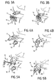
- Figures 3A, 3B illustrate, respectively in position before assembly of the battery-box assembly to the frame and in the assembled position, first means of fixing by screwing.
- Figures 4A, 4B illustrate, respectively in position before assembly of the battery-box assembly to the frame and in the assembled position, second means of fixing by interlocking.
- FIGS. 5A, 5B show, respectively in the front position assembly of the battery-box assembly to the frame and in the assembled position, third means of fixing by locking.
- FIGs 1 and 2 a vehicle is shown schematically two-wheeled, scooter type, electrically powered according to the invention.
- the vehicle 1 comprises, as is usual, a chassis (or frame) 2, connecting two front wheels 3 and rear 4, via a front suspension 5 and rear suspension 6, respectively.
- a chassis or frame 2
- the handlebars and saddle are also designated by the references numerals 7 and 8, respectively.
- Vehicle 1 also has on-board means supply of electrical energy 9, in particular batteries, housed in a housing 10 at least substantially parallelepipedal able to be fixed under frame 2 by fixing means 11, some examples of which of implementation will be described in detail below.
- electrical energy 9 in particular batteries
- the housing 10 has, on each side face 10A, 10B thereof, a footrest 12.
- FIG. 1 and 2 illustrate the ease of installation and removal of the battery-box assembly, as well as, in particular FIG. 2, the integration of this set to the chassis (or frame) 2, participating in the different functions of the latter, as already indicated above.
- Figures 3A, 3B illustrate, respectively in position before assembly of the battery-box assembly to the frame and in the assembled position, first fastening means 11 by screwing.
- the first fixing means 11 comprise, on the one hand, a yoke 13 fixed to the frame 2, and, on the other hand, a bolt 14 pivoting on an axis 15 fixed to the housing 10 by lugs 16.
- Such means 11 are advantageously provided to ensure four attachment points of the housing to the frame, and that the yoke 13 and the bolt 14 could also be provided on the housing 10 and the frame 2, respectively.
- Figures 4A, 4B illustrate, respectively in position before assembly of the battery-box assembly to the frame and in the assembled position, second fastening means 11 by interlocking.
- the second fixing means 11 comprise, on the one hand, a lug 18 fixed to the housing 10 and, on the other hand, a latch 19 articulated to fit on the lug 18, fixed to the frame 2.
- the pivoting of the latch 19 and its fitting on the lug allows the fixing of the box 10 to frame 2. It is understood that such means 11 are advantageously provided to ensure four attachment points of the housing to the frame, and that the lug 18 and the latch 19 could also be provided on the frame 2 and the housing 10, respectively.
- FIGS. 5A, 5B illustrate, respectively in position before assembly of the battery-box assembly to the frame and in the assembled position, third fastening means 11 by locking.
- the third fastening means 11 comprise, on the one hand, a yoke 20 fixed to the frame 2 and, on the other hand, a lug 18 fixed to the housing 10, a rod 21, provided with a stop 22 and a bore 23, being intended to pass through corresponding holes 24 of the yoke 20 and, passing under the lug 18 (FIG. 5B), fixing the latter to the yoke 20 thanks to a split pin 25 passing through the bore 23.
- such means 11 are advantageously designed to provide four points for fixing the box to the frame, and that the yoke 20 and the lug 18 could also be provided on the housing 10 and box 2, respectively.
Landscapes
- Engineering & Computer Science (AREA)
- Mechanical Engineering (AREA)
- Transportation (AREA)
- Chemical & Material Sciences (AREA)
- Power Engineering (AREA)
- Sustainable Energy (AREA)
- Sustainable Development (AREA)
- Life Sciences & Earth Sciences (AREA)
- Chemical Kinetics & Catalysis (AREA)
- Combustion & Propulsion (AREA)
- General Chemical & Material Sciences (AREA)
- Electrochemistry (AREA)
- Aviation & Aerospace Engineering (AREA)
- Automatic Cycles, And Cycles In General (AREA)
Abstract
Description
- d'optimiser la réalisation du châssis (ou cadre),
- de reprendre les efforts de tension, de flexion ou de compression du châssis,
- de rendre facilement interchangeables les moyens d'alimentation en énergie, notamment des batteries, et, par conséquent, d'éviter l'immobilisation du véhicule.
- rigidité du châssis,
- maintien des batteries en bloc,
- protection des batteries,
- repose-pied pour le pilote,
- élément esthétique du véhicule.
Claims (10)
- Véhicule à propulsion électrique, comportant au moins deux roues, un châssis, et des moyens embarqués d'alimentation en énergie électrique, logés dans une structure apte à être fixée de façon amovible audit châssis,
caractérisé en ce que ladite structure (10) est rigide et contribue à la rigidité globale dudit châssis (2) lorsqu'elle est fixée sur ce dernier. - Véhicule selon la revendication 1, ayant au moins deux roues reliées par un cadre,
caractérisé en ce que ladite structure rigide est un boítier (10) au moins sensiblement parallélépipédique apte à être fixé sous ledit cadre (2). - Véhicule selon la revendication 2,
caractérisé en ce que ledit boítier (10) présente, sur chaque face latérale (10A,10B) de celui-ci, un repose-pied. - Véhicule selon l'une quelconque des revendications 1 à 3,
caractérisé en ce que lesdits moyens d'alimentation en énergie électrique comprennent au moins une batterie (9). - Véhicule selon l'une quelconque des revendications 2 à 4,
caractérisé en ce que la fixation dudit boítier (10) audit cadre (2) est assurée par des moyens de fixation (11) par vissage. - Véhicule selon la revendication 5,
caractérisé en ce que lesdits moyens de fixation (11) par vissage comportent, d'une part, une chape (13) et, d'autre part, un boulon pivotant (14) dont l'écrou (17) est destiné à être serré sur ladite chape (13). - Véhicule selon l'une quelconque des revendications 2 à 4,
caractérisé en ce que la fixation dudit boítier (10) audit cadre (2) est assurée par des moyens de fixation (11) par emboítement. - Véhicule selon la revendication 7,
caractérisé en ce que lesdits moyens de fixation (11) par emboítement comportent, d'une part, un ergot (18) et, d'autre part, un loquet (19) articulé pour s'emboíter sur ledit ergot (18). - Véhicule selon l'une quelconque des revendications 2 à 4,
caractérisé en que la fixation dudit boítier (10) est assurée par des moyens de fixation (11) par verrouillage. - Véhicule selon la revendication 9,
caractérisé en ce que lesdits moyens de fixation (11) par verrouillage comportent, d'une part, une chape (20) et, d'autre part, un ergot (18), une tige (11), munie d'une butée (22) et d'un perçage (23), étant destinée à traverser des perçages (24) correspondants de ladite chape (20) et, passant sous ledit ergot (18), à fixer ce dernier à ladite chape (20) grâce à une goupille fendue (25) traversant ledit perçage (23) de ladite tige.
Applications Claiming Priority (2)
| Application Number | Priority Date | Filing Date | Title |
|---|---|---|---|
| FR9800986A FR2774044A1 (fr) | 1998-01-29 | 1998-01-29 | Vehicule a propulsion electrique |
| FR9800986 | 1998-01-29 |
Publications (1)
| Publication Number | Publication Date |
|---|---|
| EP0933291A1 true EP0933291A1 (fr) | 1999-08-04 |
Family
ID=9522326
Family Applications (1)
| Application Number | Title | Priority Date | Filing Date |
|---|---|---|---|
| EP99400197A Ceased EP0933291A1 (fr) | 1998-01-29 | 1999-01-28 | Véhicule à propulsion électrique |
Country Status (2)
| Country | Link |
|---|---|
| EP (1) | EP0933291A1 (fr) |
| FR (1) | FR2774044A1 (fr) |
Cited By (4)
| Publication number | Priority date | Publication date | Assignee | Title |
|---|---|---|---|---|
| FR2827255A1 (fr) * | 2001-07-16 | 2003-01-17 | Thierry Clerc | Un cyclo moteur a energie electrique |
| CN102602488A (zh) * | 2011-10-21 | 2012-07-25 | 苏州龙跃锂动车辆有限公司 | 电池与电动车车架的锁定机构及包括该机构的电动车 |
| FR2998848A1 (fr) * | 2012-12-04 | 2014-06-06 | Lavaud Innovations | Dispositif mobile muni d'une source d'energie electrique amovible telle une batterie |
| US20210171199A1 (en) * | 2015-06-30 | 2021-06-10 | Gopro, Inc. | Coupling Assembly for a Removable Propeller |
Families Citing this family (9)
| Publication number | Priority date | Publication date | Assignee | Title |
|---|---|---|---|---|
| US10632857B2 (en) | 2016-08-17 | 2020-04-28 | Shape Corp. | Battery support and protection structure for a vehicle |
| CN110383526A (zh) | 2017-01-04 | 2019-10-25 | 形状集团 | 节点模块化的车辆电池托盘结构 |
| US10886513B2 (en) | 2017-05-16 | 2021-01-05 | Shape Corp. | Vehicle battery tray having tub-based integration |
| US10483510B2 (en) | 2017-05-16 | 2019-11-19 | Shape Corp. | Polarized battery tray for a vehicle |
| WO2018213383A1 (fr) | 2017-05-16 | 2018-11-22 | Shape Corp. | Support de batterie de véhicule à 'éléments de retenue et de support de batterie intégrés |
| CN111108015A (zh) | 2017-09-13 | 2020-05-05 | 形状集团 | 具有管状外围壁的车辆电池托盘 |
| WO2019071013A1 (fr) | 2017-10-04 | 2019-04-11 | Shape Corp. | Ensemble fond de bac support de batterie pour véhicules électriques |
| EP3759761B1 (fr) | 2018-03-01 | 2026-04-08 | Shape Corp. | Système de refroidissement intégré à un bac de batterie de véhicule |
| US11688910B2 (en) | 2018-03-15 | 2023-06-27 | Shape Corp. | Vehicle battery tray having tub-based component |
Citations (5)
| Publication number | Priority date | Publication date | Assignee | Title |
|---|---|---|---|---|
| FR2354897A1 (fr) * | 1976-06-17 | 1978-01-13 | Peugeot | Dispositif pour l'echange rapide d'une batterie d'accumulateur sur un vehicule electrique |
| US4435486A (en) * | 1982-06-04 | 1984-03-06 | Pomaro Nicholas T | Quick disconnect battery installation and charging system |
| JPH04243677A (ja) * | 1991-01-23 | 1992-08-31 | Tokyo R & D:Kk | 電動二輪車 |
| JPH0687485A (ja) * | 1992-09-07 | 1994-03-29 | Yamaha Motor Co Ltd | 電動スクータ |
| EP0781676A2 (fr) * | 1994-09-07 | 1997-07-02 | Seiko Epson Corporation | Système d'entraînement, unité de propulsion électrique et unité de transmission de puissance pour des véhicules électriques |
-
1998
- 1998-01-29 FR FR9800986A patent/FR2774044A1/fr active Pending
-
1999
- 1999-01-28 EP EP99400197A patent/EP0933291A1/fr not_active Ceased
Patent Citations (5)
| Publication number | Priority date | Publication date | Assignee | Title |
|---|---|---|---|---|
| FR2354897A1 (fr) * | 1976-06-17 | 1978-01-13 | Peugeot | Dispositif pour l'echange rapide d'une batterie d'accumulateur sur un vehicule electrique |
| US4435486A (en) * | 1982-06-04 | 1984-03-06 | Pomaro Nicholas T | Quick disconnect battery installation and charging system |
| JPH04243677A (ja) * | 1991-01-23 | 1992-08-31 | Tokyo R & D:Kk | 電動二輪車 |
| JPH0687485A (ja) * | 1992-09-07 | 1994-03-29 | Yamaha Motor Co Ltd | 電動スクータ |
| EP0781676A2 (fr) * | 1994-09-07 | 1997-07-02 | Seiko Epson Corporation | Système d'entraînement, unité de propulsion électrique et unité de transmission de puissance pour des véhicules électriques |
Non-Patent Citations (2)
| Title |
|---|
| PATENT ABSTRACTS OF JAPAN vol. 017, no. 012 (M - 1351) 11 January 1993 (1993-01-11) * |
| PATENT ABSTRACTS OF JAPAN vol. 018, no. 348 (M - 1630) 30 June 1994 (1994-06-30) * |
Cited By (5)
| Publication number | Priority date | Publication date | Assignee | Title |
|---|---|---|---|---|
| FR2827255A1 (fr) * | 2001-07-16 | 2003-01-17 | Thierry Clerc | Un cyclo moteur a energie electrique |
| CN102602488A (zh) * | 2011-10-21 | 2012-07-25 | 苏州龙跃锂动车辆有限公司 | 电池与电动车车架的锁定机构及包括该机构的电动车 |
| FR2998848A1 (fr) * | 2012-12-04 | 2014-06-06 | Lavaud Innovations | Dispositif mobile muni d'une source d'energie electrique amovible telle une batterie |
| US20210171199A1 (en) * | 2015-06-30 | 2021-06-10 | Gopro, Inc. | Coupling Assembly for a Removable Propeller |
| US12103680B2 (en) * | 2015-06-30 | 2024-10-01 | Gopro, Inc. | Removable battery with a pull-bar to remove the battery from a chassis |
Also Published As
| Publication number | Publication date |
|---|---|
| FR2774044A1 (fr) | 1999-07-30 |
Similar Documents
| Publication | Publication Date | Title |
|---|---|---|
| EP0933291A1 (fr) | Véhicule à propulsion électrique | |
| EP3152817B1 (fr) | Ensemble stator pour moteur-roue et son support-fusée | |
| US8220578B2 (en) | Construction kit and method for converting a bicycle, and bicycle | |
| FR2538315A1 (fr) | Moyeu de bicyclette | |
| EP3492383B1 (fr) | Axe de pivotement ameliore pour une attache-moteur d'aeronef | |
| EP0381582A1 (fr) | Connecteur électrique | |
| EP2298642B1 (fr) | Dispositif de génération de courant et/ou de motorisation électrique à bord d'une structure navigante | |
| FR3065704B1 (fr) | Cadre de velo a assistance electrique | |
| WO2020065071A1 (fr) | Véhicule motorisé | |
| EP0241377B1 (fr) | Groupe motopropulseur amovible et véhicule associé tel que chariot de golf | |
| WO2001070561A1 (fr) | Support de contacts pour dispositif de securite de cycles | |
| FR3091690A1 (fr) | Système de bicyclette électrique | |
| WO2022162285A1 (fr) | Véhicule avec une structure de soubassement comprenant un dispositif de protection contre les chocs | |
| EP3165059B1 (fr) | Ensemble de fixation d'un boitier electronique et vehicule equipe d'un tel ensemble | |
| US11192019B2 (en) | Skateboard modular electric powertrain | |
| FR2802718A1 (fr) | Boite a fusibles pour vehicules automobiles | |
| FR3142149A1 (fr) | Levier de frein a main amovible en manivelle | |
| EP4437244B1 (fr) | Système de freinage ferroviaire pour véhicule ferroviaire, à freins à au moins un sabot, et véhicule ferroviaire pourvu d'un tel système | |
| FR2721875A1 (fr) | Structure de cablage pour un systeme a direction assistee electrique | |
| EP0596798A1 (fr) | Alternateur pour véhicule automobile | |
| EP0798195B1 (fr) | Dispositif de raccordement de deux arbres d'une commande de direction d'un véhicle automobile | |
| EP1679230B1 (fr) | Dispositif de fixation d'un accessoire de portage sur un fixe au toit | |
| FR3140580A1 (fr) | Machine électrique équipée d’un dispositif de frein de stationnement | |
| FR3158091A1 (fr) | Véhicule à chenille | |
| FR3142301A1 (fr) | Système de raccordement d’un outil électrique à un câble comprenant des moyens anti charbonnage |
Legal Events
| Date | Code | Title | Description |
|---|---|---|---|
| PUAI | Public reference made under article 153(3) epc to a published international application that has entered the european phase |
Free format text: ORIGINAL CODE: 0009012 |
|
| AK | Designated contracting states |
Kind code of ref document: A1 Designated state(s): AT BE CH CY DE DK ES FI GB GR IE IT LI LU MC NL PT SE |
|
| AX | Request for extension of the european patent |
Free format text: AL;LT;LV;MK;RO;SI |
|
| 17P | Request for examination filed |
Effective date: 19990908 |
|
| AKX | Designation fees paid |
Free format text: AT BE CH CY DE DK ES FI GB GR IE IT LI LU MC NL PT SE |
|
| 17Q | First examination report despatched |
Effective date: 20030410 |
|
| STAA | Information on the status of an ep patent application or granted ep patent |
Free format text: STATUS: THE APPLICATION HAS BEEN REFUSED |
|
| 18R | Application refused |
Effective date: 20041211 |