EP0933076B1 - Head rest assembly for spas and whirlpools - Google Patents
Head rest assembly for spas and whirlpools Download PDFInfo
- Publication number
- EP0933076B1 EP0933076B1 EP99107117A EP99107117A EP0933076B1 EP 0933076 B1 EP0933076 B1 EP 0933076B1 EP 99107117 A EP99107117 A EP 99107117A EP 99107117 A EP99107117 A EP 99107117A EP 0933076 B1 EP0933076 B1 EP 0933076B1
- Authority
- EP
- European Patent Office
- Prior art keywords
- head rest
- pillow
- nozzle
- nozzles
- rest assembly
- Prior art date
- Legal status (The legal status is an assumption and is not a legal conclusion. Google has not performed a legal analysis and makes no representation as to the accuracy of the status listed.)
- Expired - Lifetime
Links
Images


Classifications
-
- A—HUMAN NECESSITIES
- A61—MEDICAL OR VETERINARY SCIENCE; HYGIENE
- A61H—PHYSICAL THERAPY APPARATUS, e.g. DEVICES FOR LOCATING OR STIMULATING REFLEX POINTS IN THE BODY; ARTIFICIAL RESPIRATION; MASSAGE; BATHING DEVICES FOR SPECIAL THERAPEUTIC OR HYGIENIC PURPOSES OR SPECIFIC PARTS OF THE BODY
- A61H23/00—Percussion or vibration massage, e.g. using supersonic vibration; Suction-vibration massage; Massage with moving diaphragms
- A61H23/04—Percussion or vibration massage, e.g. using supersonic vibration; Suction-vibration massage; Massage with moving diaphragms with hydraulic or pneumatic drive
-
- A—HUMAN NECESSITIES
- A61—MEDICAL OR VETERINARY SCIENCE; HYGIENE
- A61H—PHYSICAL THERAPY APPARATUS, e.g. DEVICES FOR LOCATING OR STIMULATING REFLEX POINTS IN THE BODY; ARTIFICIAL RESPIRATION; MASSAGE; BATHING DEVICES FOR SPECIAL THERAPEUTIC OR HYGIENIC PURPOSES OR SPECIFIC PARTS OF THE BODY
- A61H33/00—Bathing devices for special therapeutic or hygienic purposes
- A61H33/60—Components specifically designed for the therapeutic baths of groups A61H33/00
- A61H33/601—Inlet to the bath
- A61H33/6021—Nozzles
- A61H33/6063—Specifically adapted for fitting in bathtub walls
-
- A—HUMAN NECESSITIES
- A61—MEDICAL OR VETERINARY SCIENCE; HYGIENE
- A61H—PHYSICAL THERAPY APPARATUS, e.g. DEVICES FOR LOCATING OR STIMULATING REFLEX POINTS IN THE BODY; ARTIFICIAL RESPIRATION; MASSAGE; BATHING DEVICES FOR SPECIAL THERAPEUTIC OR HYGIENIC PURPOSES OR SPECIFIC PARTS OF THE BODY
- A61H2201/00—Characteristics of apparatus not provided for in the preceding codes
- A61H2201/12—Driving means
- A61H2201/1207—Driving means with electric or magnetic drive
-
- A—HUMAN NECESSITIES
- A61—MEDICAL OR VETERINARY SCIENCE; HYGIENE
- A61H—PHYSICAL THERAPY APPARATUS, e.g. DEVICES FOR LOCATING OR STIMULATING REFLEX POINTS IN THE BODY; ARTIFICIAL RESPIRATION; MASSAGE; BATHING DEVICES FOR SPECIAL THERAPEUTIC OR HYGIENIC PURPOSES OR SPECIFIC PARTS OF THE BODY
- A61H2201/00—Characteristics of apparatus not provided for in the preceding codes
- A61H2201/16—Physical interface with patient
- A61H2201/1602—Physical interface with patient kind of interface, e.g. head rest, knee support or lumbar support
- A61H2201/1609—Neck
-
- A—HUMAN NECESSITIES
- A61—MEDICAL OR VETERINARY SCIENCE; HYGIENE
- A61H—PHYSICAL THERAPY APPARATUS, e.g. DEVICES FOR LOCATING OR STIMULATING REFLEX POINTS IN THE BODY; ARTIFICIAL RESPIRATION; MASSAGE; BATHING DEVICES FOR SPECIAL THERAPEUTIC OR HYGIENIC PURPOSES OR SPECIFIC PARTS OF THE BODY
- A61H2201/00—Characteristics of apparatus not provided for in the preceding codes
- A61H2201/16—Physical interface with patient
- A61H2201/1602—Physical interface with patient kind of interface, e.g. head rest, knee support or lumbar support
- A61H2201/1654—Layer between the skin and massage elements, e.g. fluid or ball
-
- A—HUMAN NECESSITIES
- A61—MEDICAL OR VETERINARY SCIENCE; HYGIENE
- A61H—PHYSICAL THERAPY APPARATUS, e.g. DEVICES FOR LOCATING OR STIMULATING REFLEX POINTS IN THE BODY; ARTIFICIAL RESPIRATION; MASSAGE; BATHING DEVICES FOR SPECIAL THERAPEUTIC OR HYGIENIC PURPOSES OR SPECIFIC PARTS OF THE BODY
- A61H2201/00—Characteristics of apparatus not provided for in the preceding codes
- A61H2201/50—Control means thereof
- A61H2201/5007—Control means thereof computer controlled
-
- A—HUMAN NECESSITIES
- A61—MEDICAL OR VETERINARY SCIENCE; HYGIENE
- A61H—PHYSICAL THERAPY APPARATUS, e.g. DEVICES FOR LOCATING OR STIMULATING REFLEX POINTS IN THE BODY; ARTIFICIAL RESPIRATION; MASSAGE; BATHING DEVICES FOR SPECIAL THERAPEUTIC OR HYGIENIC PURPOSES OR SPECIFIC PARTS OF THE BODY
- A61H2205/00—Devices for specific parts of the body
- A61H2205/04—Devices for specific parts of the body neck
-
- A—HUMAN NECESSITIES
- A61—MEDICAL OR VETERINARY SCIENCE; HYGIENE
- A61H—PHYSICAL THERAPY APPARATUS, e.g. DEVICES FOR LOCATING OR STIMULATING REFLEX POINTS IN THE BODY; ARTIFICIAL RESPIRATION; MASSAGE; BATHING DEVICES FOR SPECIAL THERAPEUTIC OR HYGIENIC PURPOSES OR SPECIFIC PARTS OF THE BODY
- A61H33/00—Bathing devices for special therapeutic or hygienic purposes
- A61H33/0087—Therapeutic baths with agitated or circulated water
Landscapes
- Health & Medical Sciences (AREA)
- Public Health (AREA)
- Epidemiology (AREA)
- Pain & Pain Management (AREA)
- Physical Education & Sports Medicine (AREA)
- Rehabilitation Therapy (AREA)
- Life Sciences & Earth Sciences (AREA)
- Animal Behavior & Ethology (AREA)
- General Health & Medical Sciences (AREA)
- Veterinary Medicine (AREA)
- Massaging Devices (AREA)
- Percussion Or Vibration Massage (AREA)
- Devices For Medical Bathing And Washing (AREA)
Description
- The present invention relates primarily to bathing fixtures such as hydro-message spas and whirlpools. More particularly, it relates to a head rest member for use with such bathing fixtures.
- It is known to provide head rest members in bathing fixtures. US Application No. 4,860,392 shows the flow of a fluid stream against a flexible material to effect a massaging action as do US Application Nos. 4,635,619 and 4,953,240. See also US Application No. 5,010,605.
- Although the prior art teaches various types of body support or neck massage devices for use with bathing fixtures, there is not available a head support and spray nozzle assembly in which the spray nozzle assembly can conform to various wall surfaces of the bathing fixture.
- The present invention provides:
- a head rest assembly for use in conjunction with a bathing fixture comprising:
- a body member including a section to support a head;
- a fluid inlet nozzle for providing fluid to the body member; and a support bracket connected to the body member and the nozzle; characterized by a second fluid inlet nozzle for providing fluid to the body member, and a living hinge interconnecting the nozzles.
-
- In the detailed description below, the preferred embodiments of the invention will be described in reference to the accompanying drawings. These embodiments do not represent the full scope of the invention. Rather the invention may be employed in other embodiments. Reference should therefore be made to the claims herein for interpreting the breadth of the invention.
-
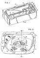
- Fig. 1 is a top perspective view of a whirlpool tub which incorporates the present head rest assembly;
- Fig. 2 is a sectional view taken along line 2-2 of Fig. 1;
- Fig. 3 is a sectional view taken along line 3-3 of Fig. 2;
- Fig. 4 is a sectional view taken along line 4-4 of Fig. 3;
- Fig. 5 is a partial perspective view similar to Fig. 1 showing an alternative embodiment;
- Fig. 6 is a sectional view taken along line 6-6 of Fig. 5;
- Fig. 7 is a bottom view taken along line 7-7 of Fig. 6;
- Fig. 8 is a sectional view taken along line 8-8 of Fig. 6;
- Fig. 9 is a view in side elevation (with partial showing) illustrating the head rest assembly connected to nozzles;
- Fig. 10 is a partial sectional view taken along line 10-10 of Fig. 9;
- Fig. 11 is an exploded view of the head rest assembly and nozzle members shown in Fig. 6; and
- Fig. 12 is a top perspective view of the nozzle members shown in Fig. 11.
-
- Referring specifically to Figs. 1 and 2, the head rest assembly, generally 10, is employed in conjunction with a hydro-massage whirlpool, generally 12, which includes a
tub 14 having a plurality ofconventional whirlpool nozzles 15 projecting through an interior side wall such as 17. The tub has theusual floor 18 with a standard drain opening 19. Asoft cushion 13 is attached to the rim of the tub aboveend wall 20 with thehead rest assembly 10 positioned centrally therein. Also positioned inend wall 20 arenozzles 21 which are arranged in pairs except for the outer two nozzles 21'. - Referring to Figs. 2 and 3, the
head rest assembly 10 includes a pillow 11 having a generally C-shaped configuration with acentral section 24 and twoleg sections 26 and 27. The pillow is preferably composed of a self-skinning urethane foam and has a fine mesh,fabric cover 16 extending thereover. The primary purpose of the fabric cover is to provide a dampening or softening of the force of the water jet stream fromnozzles drain net 25 is connected tocover 16 for placement between theleg sections 26 and 27 and extending fromcentral section 24. This provides a drainage of the water from the pillow. The pillow is preferably molded around abracket 30 composed of polypropylene. Thebracket 30 also has acentral section 28 and twoleg sections nozzles nozzles - As seen in Fig. 3, the nozzles such as 33 are held in place and connected to the
tub wall 20 by thenut 36 and thewasher 35 with a threadedconnection 37 provided between thenozzle 33 and thenut 36. Water is supplied to the nozzle such as through theusual conduit 57. A magnet 50 is housed in thebracket 30 and is utilized to activate areed switch 45. Asupport surface 38 for thebracket 30 is provided by thenozzle body 43. Anozzle cover 44 is connected tonozzle 33 such as by the hooked portion 44' engaging flanged portion 33' ofnozzle 33. - As shown in Fig. 4, the
reed switch 45 is connected to theelectrical lines nozzles central body section 39 ofnozzle body 43 having aliving hinge 40 provided bycutout 46. Thenozzles central body section 39, are molded from a semi-rigid plastic material. Theliving hinge 40 allows a hinging action between the twonozzles peripheral groove 49 is provided for connection with thebracket 30. - Figs. 5-10 show an alternative embodiment. Similar numbers refer to the same or similar components as described with
embodiment 10 except they are designated with the suffix "A". The major difference between the two embodiments is that embodiment 10A includes a different pillow design having the centralconcave portions body 23A. This is seen in Fig. 7. Further, another difference is alip portion 56A which extends from the back of pillow 10A and over the top of thetub 14A. This is utilized to cover the side wall of thetub 14A where it is curved. In many instances, thetub 14A will not have a major curvature and consequently the lip can be eliminated. In addition, and as seen in Fig.8, it is noted that the pillow 11A has acurved wall section 58A to accommodate the uppercurved wall 20A of the tub, as well as a lowerflat edge portion 55A. - It is seen that embodiment 10A does not have the
drain net 25 in conjunction with the cover 1 6A. Drainage is afforded instead by aconcave portion 54A extending along the backside of pillow 11A between theleg portions - Although not shown in the drawings, a pillow in the general shape of a boomerang can be used. It would not have the drain net 25 or concave portion 54. Instead a recessed channel would be present in the back of the pillow which serves the same drainage result.
- Figs. 9, 10 and 11 show the attachment of the
pillow bracket 30A to thenozzles peripheral groove 49A extends around thenozzles inner edge portion 59A of thebracket 30A which terminates in thetabs - Fig. 12 shows in further detail the
living hinge 40A as provided by thecutout 46A in thecentral section 39A of thenozzle body 43A. - Referring specifically to Fig. 6, the pillow 11A is shown as extending from
end wall 20A with a portion extending overtop rim 22A. It is not used with thecushion 13 shown in Fig. 1. If desired, it can be incorporated into a cushion or another pillow such as 13 with the cushion being cut out to conform to the oval shape of pillow 11A. - Thus, the invention provides an improved head rest member for use in conjunction with a hydro-massage whirlpool. A pillow is provided as a head rest member which is easily attached and supported by the neck massage nozzles. The pillow can be of various designs to complement the configuration of the wall of the whirlpool. It also has a cover which can be decorated with various aesthetic designs and colors. In addition, a unique nozzle unit is provided having a living hinge which can accommodate the wall configurations of the whirlpool.
- As previously indicated, the pillow can be of various configurations and incorporated in a cushion, or it can also be utilized without it. Certain materials have been utilized in composing different elements of the pillow, the bracket and the nozzle. Obviously, other materials can be advantageously employed.
Claims (1)
- A head rest assembly for use in conjunction with a bathing fixture comprising:a body member (10, 10A) including a section to support a head;a fluid inlet nozzle (32, 32A) for providing fluid to the body member; and a support bracket connected to the body member and the nozzle, characterized by a second fluid inlet nozzle (33, 33A) for providing fluid to the body member (10, 10A), anda living hinge (40, 40A) interconnecting the nozzles.
Applications Claiming Priority (3)
| Application Number | Priority Date | Filing Date | Title |
|---|---|---|---|
| US376575 | 1989-07-07 | ||
| US08/376,575 US5546616A (en) | 1993-08-16 | 1995-01-23 | Head rest assembly |
| EP96906168A EP0806930B9 (en) | 1995-01-23 | 1996-01-03 | Head rest assembly for spas and whirlpools |
Related Parent Applications (1)
| Application Number | Title | Priority Date | Filing Date |
|---|---|---|---|
| EP96906168A Division EP0806930B9 (en) | 1995-01-23 | 1996-01-03 | Head rest assembly for spas and whirlpools |
Publications (3)
| Publication Number | Publication Date |
|---|---|
| EP0933076A2 EP0933076A2 (en) | 1999-08-04 |
| EP0933076A3 EP0933076A3 (en) | 1999-12-29 |
| EP0933076B1 true EP0933076B1 (en) | 2004-06-02 |
Family
ID=23485563
Family Applications (2)
| Application Number | Title | Priority Date | Filing Date |
|---|---|---|---|
| EP96906168A Expired - Lifetime EP0806930B9 (en) | 1995-01-23 | 1996-01-03 | Head rest assembly for spas and whirlpools |
| EP99107117A Expired - Lifetime EP0933076B1 (en) | 1995-01-23 | 1996-01-03 | Head rest assembly for spas and whirlpools |
Family Applications Before (1)
| Application Number | Title | Priority Date | Filing Date |
|---|---|---|---|
| EP96906168A Expired - Lifetime EP0806930B9 (en) | 1995-01-23 | 1996-01-03 | Head rest assembly for spas and whirlpools |
Country Status (6)
| Country | Link |
|---|---|
| US (2) | US5546616A (en) |
| EP (2) | EP0806930B9 (en) |
| AU (1) | AU4963696A (en) |
| DE (3) | DE69632647T2 (en) |
| ES (2) | ES2222634T3 (en) |
| WO (1) | WO1996022759A1 (en) |
Families Citing this family (10)
| Publication number | Priority date | Publication date | Assignee | Title |
|---|---|---|---|---|
| US6186964B1 (en) * | 1996-09-27 | 2001-02-13 | Tony J. Branham | Hydro-massage pillow system |
| US6351859B1 (en) | 1997-08-19 | 2002-03-05 | John V. Maiuccoro | Hydrotherapy tub coplanar flow |
| MXPA01000893A (en) * | 1998-07-27 | 2002-06-04 | Webtv Networks Inc | Remote computer access. |
| US7597652B2 (en) * | 2001-11-28 | 2009-10-06 | Dimension One Spas | Hydrotherapy mounting apparatus and exercise system |
| CA2491782C (en) * | 2004-01-06 | 2012-05-22 | C.G. Air Systemes Inc. | Cushion system for a washing/bathing tub |
| US20090089926A1 (en) * | 2007-10-04 | 2009-04-09 | Larsen Christopher C | Spa shell pillow |
| US8141181B2 (en) * | 2007-12-04 | 2012-03-27 | Aquatic Co. | Neck jet pillow for whirlpool tub or spa |
| US7996932B2 (en) * | 2008-03-28 | 2011-08-16 | Elnar Joseph G | Spa wall mounted water jet neck and shoulder massager |
| CN115282020A (en) * | 2017-02-28 | 2022-11-04 | Toto株式会社 | Bath tank |
| US11951071B2 (en) * | 2019-11-25 | 2024-04-09 | Sundance Spas, Inc. | Heated massage pillow |
Family Cites Families (15)
| Publication number | Priority date | Publication date | Assignee | Title |
|---|---|---|---|---|
| US1994413A (en) * | 1933-02-04 | 1935-03-12 | Webster Luther Thomas | Bath spray brush |
| US2544745A (en) * | 1947-07-08 | 1951-03-13 | Westinghouse Electric Corp | Waste disposal apparatus |
| US2964248A (en) * | 1955-11-18 | 1960-12-13 | Spraying Systems Co | Plural orifice fan shaped spray nozzle |
| US3646883A (en) * | 1970-10-19 | 1972-03-07 | Rockford Iron Works Inc | Punch press with swing-out control panel |
| US3803943A (en) * | 1972-11-01 | 1974-04-16 | Chrysler Corp | Machine guard |
| US4313432A (en) * | 1979-01-31 | 1982-02-02 | Sievers George K | Water driven personal massager |
| US4635619A (en) * | 1984-01-20 | 1987-01-13 | Diamond Harvey E | Water massager means |
| US4541130A (en) * | 1984-04-10 | 1985-09-17 | Owens-Corning Fiberglas Corporation | Bathtub assembly |
| US4837870A (en) * | 1985-03-18 | 1989-06-13 | Wiley Robert B | Spa overflow system |
| US4635319A (en) * | 1985-10-25 | 1987-01-13 | Gast Daniel A | Skinning device |
| US4630599A (en) * | 1986-01-31 | 1986-12-23 | Unidyne, Inc. | Hydromassage apparatus |
| US4953240A (en) * | 1987-10-20 | 1990-09-04 | Saratoga Spa & Bath Company | Hydrotherapy massage unit |
| US4860392A (en) * | 1987-10-20 | 1989-08-29 | John Gardenier | Hydrotherapy massage unit |
| US5010605A (en) * | 1988-04-13 | 1991-04-30 | Ricoh Company, Ltd. | Body massaging apparatus of water current type |
| US5039058A (en) * | 1990-07-10 | 1991-08-13 | Boeshart Patrick E | Hinged tie for forming angles walls |
-
1995
- 1995-01-23 US US08/376,575 patent/US5546616A/en not_active Expired - Lifetime
-
1996
- 1996-01-03 ES ES99107117T patent/ES2222634T3/en not_active Expired - Lifetime
- 1996-01-03 EP EP96906168A patent/EP0806930B9/en not_active Expired - Lifetime
- 1996-01-03 WO PCT/US1996/000540 patent/WO1996022759A1/en active IP Right Grant
- 1996-01-03 AU AU49636/96A patent/AU4963696A/en not_active Abandoned
- 1996-01-03 DE DE69632647T patent/DE69632647T2/en not_active Expired - Lifetime
- 1996-01-03 EP EP99107117A patent/EP0933076B1/en not_active Expired - Lifetime
- 1996-01-03 DE DE69612837T patent/DE69612837T4/en not_active Expired - Lifetime
- 1996-01-03 ES ES96906168T patent/ES2159724T3/en not_active Expired - Lifetime
- 1996-01-03 DE DE69612837A patent/DE69612837D1/en not_active Expired - Lifetime
- 1996-03-20 US US08/619,900 patent/US5617591A/en not_active Expired - Lifetime
Also Published As
| Publication number | Publication date |
|---|---|
| EP0933076A2 (en) | 1999-08-04 |
| AU4963696A (en) | 1996-08-14 |
| DE69632647D1 (en) | 2004-07-08 |
| WO1996022759A1 (en) | 1996-08-01 |
| ES2222634T3 (en) | 2005-02-01 |
| US5617591A (en) | 1997-04-08 |
| DE69632647T2 (en) | 2005-05-25 |
| EP0806930A1 (en) | 1997-11-19 |
| US5546616A (en) | 1996-08-20 |
| DE69612837D1 (en) | 2001-06-21 |
| EP0806930B1 (en) | 2001-05-16 |
| ES2159724T3 (en) | 2001-10-16 |
| EP0806930B9 (en) | 2002-05-15 |
| DE69612837T4 (en) | 2003-07-24 |
| EP0933076A3 (en) | 1999-12-29 |
| DE69612837T2 (en) | 2002-03-28 |
Similar Documents
| Publication | Publication Date | Title |
|---|---|---|
| CA2199420C (en) | Neck massage pillow for spa apparatus | |
| EP0933076B1 (en) | Head rest assembly for spas and whirlpools | |
| US4926510A (en) | Hand held dry hydro-massage unit for a spa | |
| US7013503B2 (en) | Tactile therapy system for spas | |
| US5333324A (en) | Hydrotherapy hot tub structure for neck and shoulder massage | |
| US6859954B2 (en) | Alcove whirlpool seat spa system | |
| GB2153682A (en) | Vibratory massage device | |
| US1677160A (en) | Bathtub | |
| CA2559212C (en) | Head rest assembly for spas and whirlpools | |
| CA2211172C (en) | Head rest assembly for spas and whirlpools | |
| US5588160A (en) | Total body brush shower | |
| US4908888A (en) | Dry hydro-massage unit | |
| CA1317415C (en) | Dry hydro-massage unit | |
| US7290298B2 (en) | Massage pad for bath | |
| CA2039801A1 (en) | Device to be connected to a bottom and/or a wall of a sanitary apparatus for supplying air and/or water into the water-filled sanitary apparatus | |
| KR200163457Y1 (en) | Bath equipment for bath house | |
| KR200269789Y1 (en) | Toilet seat cover sheet with ventilation and acupressure function | |
| US11702824B2 (en) | Systems and methods for diverting water from a shower head and distributing within a bathtub or shower basin | |
| KR200291539Y1 (en) | Shower flag head | |
| KR870001962Y1 (en) | An aeration pannel of the bathtub | |
| JP2917850B2 (en) | Shower equipment | |
| JP3121473B2 (en) | Shower device for bathtub shoulder rest | |
| KR20000017955U (en) | Head pillow which can be stuck or taken off from bathtub | |
| CA2307436A1 (en) | Bathtub design | |
| JP2003310695A (en) | Vortex flow bathing apparatus |
Legal Events
| Date | Code | Title | Description |
|---|---|---|---|
| PUAI | Public reference made under article 153(3) epc to a published international application that has entered the european phase |
Free format text: ORIGINAL CODE: 0009012 |
|
| AC | Divisional application: reference to earlier application |
Ref document number: 806930 Country of ref document: EP |
|
| AK | Designated contracting states |
Kind code of ref document: A2 Designated state(s): DE ES FR GB IT NL |
|
| PUAL | Search report despatched |
Free format text: ORIGINAL CODE: 0009013 |
|
| AK | Designated contracting states |
Kind code of ref document: A3 Designated state(s): DE ES FR GB IT NL |
|
| RIN1 | Information on inventor provided before grant (corrected) |
Inventor name: THOMAS, CARTER J. Inventor name: GIESE, ROBERT C. Inventor name: KURTH, MICHAEL J. Inventor name: HALLORAN, DANIEL N. Inventor name: POTTER, EDWIN R. JR. Inventor name: DANNENBERG, TODD D. Inventor name: BENGTSON, ALAN D. Inventor name: BLOEMER, JOHN M. |
|
| 17P | Request for examination filed |
Effective date: 20000616 |
|
| GRAH | Despatch of communication of intention to grant a patent |
Free format text: ORIGINAL CODE: EPIDOS IGRA |
|
| GRAS | Grant fee paid |
Free format text: ORIGINAL CODE: EPIDOSNIGR3 |
|
| DAX | Request for extension of the european patent (deleted) | ||
| GRAA | (expected) grant |
Free format text: ORIGINAL CODE: 0009210 |
|
| AC | Divisional application: reference to earlier application |
Ref document number: 0806930 Country of ref document: EP Kind code of ref document: P |
|
| AK | Designated contracting states |
Kind code of ref document: B1 Designated state(s): DE ES FR GB IT NL |
|
| REG | Reference to a national code |
Ref country code: GB Ref legal event code: FG4D |
|
| REF | Corresponds to: |
Ref document number: 69632647 Country of ref document: DE Date of ref document: 20040708 Kind code of ref document: P |
|
| REG | Reference to a national code |
Ref country code: ES Ref legal event code: FG2A Ref document number: 2222634 Country of ref document: ES Kind code of ref document: T3 |
|
| ET | Fr: translation filed | ||
| PLBE | No opposition filed within time limit |
Free format text: ORIGINAL CODE: 0009261 |
|
| STAA | Information on the status of an ep patent application or granted ep patent |
Free format text: STATUS: NO OPPOSITION FILED WITHIN TIME LIMIT |
|
| 26N | No opposition filed |
Effective date: 20050303 |
|
| PGFP | Annual fee paid to national office [announced via postgrant information from national office to epo] |
Ref country code: FR Payment date: 20110126 Year of fee payment: 16 Ref country code: NL Payment date: 20110124 Year of fee payment: 16 Ref country code: IT Payment date: 20110127 Year of fee payment: 16 Ref country code: DE Payment date: 20110117 Year of fee payment: 16 |
|
| PGFP | Annual fee paid to national office [announced via postgrant information from national office to epo] |
Ref country code: GB Payment date: 20110119 Year of fee payment: 16 |
|
| REG | Reference to a national code |
Ref country code: NL Ref legal event code: V1 Effective date: 20120801 |
|
| GBPC | Gb: european patent ceased through non-payment of renewal fee |
Effective date: 20120103 |
|
| REG | Reference to a national code |
Ref country code: FR Ref legal event code: ST Effective date: 20120928 |
|
| PG25 | Lapsed in a contracting state [announced via postgrant information from national office to epo] |
Ref country code: GB Free format text: LAPSE BECAUSE OF NON-PAYMENT OF DUE FEES Effective date: 20120103 Ref country code: DE Free format text: LAPSE BECAUSE OF NON-PAYMENT OF DUE FEES Effective date: 20120801 |
|
| REG | Reference to a national code |
Ref country code: DE Ref legal event code: R119 Ref document number: 69632647 Country of ref document: DE Effective date: 20120801 |
|
| PG25 | Lapsed in a contracting state [announced via postgrant information from national office to epo] |
Ref country code: IT Free format text: LAPSE BECAUSE OF NON-PAYMENT OF DUE FEES Effective date: 20120103 |
|
| PG25 | Lapsed in a contracting state [announced via postgrant information from national office to epo] |
Ref country code: FR Free format text: LAPSE BECAUSE OF NON-PAYMENT OF DUE FEES Effective date: 20120131 |
|
| PG25 | Lapsed in a contracting state [announced via postgrant information from national office to epo] |
Ref country code: NL Free format text: LAPSE BECAUSE OF NON-PAYMENT OF DUE FEES Effective date: 20120801 |
|
| PGFP | Annual fee paid to national office [announced via postgrant information from national office to epo] |
Ref country code: ES Payment date: 20120213 Year of fee payment: 17 |
|
| REG | Reference to a national code |
Ref country code: ES Ref legal event code: FD2A Effective date: 20140321 |
|
| PG25 | Lapsed in a contracting state [announced via postgrant information from national office to epo] |
Ref country code: ES Free format text: LAPSE BECAUSE OF NON-PAYMENT OF DUE FEES Effective date: 20130104 |