EP0933042A2 - Articulated broom - Google Patents
Articulated broom Download PDFInfo
- Publication number
- EP0933042A2 EP0933042A2 EP99101100A EP99101100A EP0933042A2 EP 0933042 A2 EP0933042 A2 EP 0933042A2 EP 99101100 A EP99101100 A EP 99101100A EP 99101100 A EP99101100 A EP 99101100A EP 0933042 A2 EP0933042 A2 EP 0933042A2
- Authority
- EP
- European Patent Office
- Prior art keywords
- pin
- handle
- hub
- joint
- base
- Prior art date
- Legal status (The legal status is an assumption and is not a legal conclusion. Google has not performed a legal analysis and makes no representation as to the accuracy of the status listed.)
- Granted
Links
Images
Classifications
-
- A—HUMAN NECESSITIES
- A46—BRUSHWARE
- A46B—BRUSHES
- A46B5/00—Brush bodies; Handles integral with brushware
- A46B5/002—Brush bodies; Handles integral with brushware having articulations, joints or flexible portions
- A46B5/0054—Brush bodies; Handles integral with brushware having articulations, joints or flexible portions designed to allow relative positioning of the head to body
-
- A—HUMAN NECESSITIES
- A46—BRUSHWARE
- A46B—BRUSHES
- A46B2200/00—Brushes characterized by their functions, uses or applications
- A46B2200/30—Brushes for cleaning or polishing
- A46B2200/302—Broom
-
- Y—GENERAL TAGGING OF NEW TECHNOLOGICAL DEVELOPMENTS; GENERAL TAGGING OF CROSS-SECTIONAL TECHNOLOGIES SPANNING OVER SEVERAL SECTIONS OF THE IPC; TECHNICAL SUBJECTS COVERED BY FORMER USPC CROSS-REFERENCE ART COLLECTIONS [XRACs] AND DIGESTS
- Y10—TECHNICAL SUBJECTS COVERED BY FORMER USPC
- Y10T—TECHNICAL SUBJECTS COVERED BY FORMER US CLASSIFICATION
- Y10T403/00—Joints and connections
- Y10T403/32—Articulated members
- Y10T403/32254—Lockable at fixed position
- Y10T403/32262—At selected angle
- Y10T403/32319—At selected angle including pivot stud
- Y10T403/32409—Members locked in axial alignment
Definitions
- the present invention relates to an articulated broom.
- a number of different brooms are currently commercially available which have a joint between the handle and the base comprising an attachment plane for the bristles which, during use, make contact with the surfaces to be cleaned.
- the aim of the present invention is to provide an articulated broom which is very simple from the structural point of view.
- an object of the present invention is to provide an articulated broom which has a high functional efficiency, offers a wide range of operating possibilities, and is user-friendly.
- an articulated broom characterized in that it comprises a joint located between a base having an attachment plane for the bristles and the end of the handle, said joint comprising a pin connected to said base and adapted to allow the rotation of a hub which is located at the end of the handle and attached to said pin in such a way as to provide a certain amount of friction therebetween; abutment means of the hub being provided in a first end position in which the axis of the handle is perpendicular to the bristles attachment plane, and in a second end position, whereby rotation of the hub is allowed in only one direction starting from said first end position.
- 1 generally designates the base of the broom which is provided with an attachment plane 2 for the bristles 3.
- the longitudinal axis of said base is designated by 1a.
- the handle 4 of the broom extends along an axis 4a and has its lower end shaped as a bushing 4b which is rigidly coupled to said handle.
- a joint which comprises a pin 5 having an axis 5a.
- the pin is connected to said base, by extending from and being monolithical with two faces 6a, 6b forming part of the base.
- Said pin is adapted to allow the rotation of a hub 7 extending from the bushing 4b, and being monolithical therewith, at the lower end of the handle 4.
- the axis 5a of the pin 5 is contained in a plane perpendicular to the longitudinal axis 1a of the base 1, and forms an angle 8 being substantially of 45° (see Figure 3) with respect to the attachment plane 2 of the bristles 3.
- the hub 7 is also inclined, at an angle indicated with 9 in Figure 3, being substantially of 45° with respect to the axis 4a of the handle 4.
- the broom according to the invention is provided with abutment means for the hub 7 at the two end positions, which consists of teeth 10a, 10b.
- abutment means for the hub 7 at the two end positions, which consists of teeth 10a, 10b.
- teeth 10a, 10b ensures that the handle 4 is held in position when it is in either of the two end positions.
- the handle can further assume several intermediate positions during rotation thereof between the two end positions. In this manner the broom has greater handling capability in all situations. These intermediate positions are maintained thanks to the friction provided between the hub 7 and the faces 6a, 6b from which the pin 5 extends.
- said hub comprises a housing 11 for the pin 5 adapted to enclose said pin along an arcuated surface substantially equal to a semi-circumference ending with two lugs 12, 13.
- Two wings 14, 15 extend from the hub body parallel to the lugs 12, 13 and bend towards the housing 11 so as to provide therealong a complete retention of the pin 5. In this way the wings also achieve the necessary elasticity to allow the insertion of said pin 5 therebetween, when said pin is placed into the housing 11.
- the friction that the hub 7 meets during its rotation can be provided by its contact with the pin 5.
- abutment means for the hub suitably located, may allow the rotation between a first end position, such as that mentioned above, and any other second end position.
Abstract
Description
- The present invention relates to an articulated broom.
- A number of different brooms are currently commercially available which have a joint between the handle and the base comprising an attachment plane for the bristles which, during use, make contact with the surfaces to be cleaned.
- All conventional brooms however have only a limited functionality and are complicated from the structural point of view.
- The aim of the present invention is to provide an articulated broom which is very simple from the structural point of view.
- Within the scope of this aim, an object of the present invention is to provide an articulated broom which has a high functional efficiency, offers a wide range of operating possibilities, and is user-friendly.
- This aim, this object and others which will become apparent hereinafter are achieved by an articulated broom according to the invention, characterized in that it comprises a joint located between a base having an attachment plane for the bristles and the end of the handle, said joint comprising a pin connected to said base and adapted to allow the rotation of a hub which is located at the end of the handle and attached to said pin in such a way as to provide a certain amount of friction therebetween; abutment means of the hub being provided in a first end position in which the axis of the handle is perpendicular to the bristles attachment plane, and in a second end position, whereby rotation of the hub is allowed in only one direction starting from said first end position.
- Further characteristics and advantages of the present invention will become apparent from the following detailed description of a preferred but not exclusive embodiment thereof, illustrated only by way of non-limitative example in the accompanying drawings, wherein:
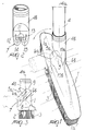
- Figure 1 is a perspective view of the broom with the handle thereof represented in its two stroke end positions, respectively illustrated with a solid line and a chain-dot line;
- Figure 2 shows the detail of the hub located at the end of the handle; and
- Figure 3 is a side view of the broom with the handle in the same conditions as depicted in Figure 1.
-
- With reference to the above figures, 1 generally designates the base of the broom which is provided with an
attachment plane 2 for thebristles 3. The longitudinal axis of said base is designated by 1a. Thehandle 4 of the broom extends along anaxis 4a and has its lower end shaped as a bushing 4b which is rigidly coupled to said handle. - Between the base 1 and the
handle 4 a joint is located which comprises a pin 5 having anaxis 5a. The pin is connected to said base, by extending from and being monolithical with twofaces 6a, 6b forming part of the base. Said pin is adapted to allow the rotation of ahub 7 extending from the bushing 4b, and being monolithical therewith, at the lower end of thehandle 4. - Particularly, the
axis 5a of the pin 5 is contained in a plane perpendicular to thelongitudinal axis 1a of the base 1, and forms anangle 8 being substantially of 45° (see Figure 3) with respect to theattachment plane 2 of thebristles 3. Thehub 7 is also inclined, at an angle indicated with 9 in Figure 3, being substantially of 45° with respect to theaxis 4a of thehandle 4. - Therefore, it is possible to rotate the handle of the broom, in a plane being perpendicular to said
attachment plane 2, between the two end positions shown in Figures 1 and 3 : a first position, shown in solid lines, in which thehandle 4 has itsaxis 4a perpendicular to theattachment plane 2 for the bristles, and a second position, shown in chain-dot lines, in which the axis of said handle is parallel to saidplane 2 while being still perpendicular with respect to thelongitudinal axis 1a of the base 1. - The broom according to the invention is provided with abutment means for the
hub 7 at the two end positions, which consists ofteeth 10a, 10b. Thus the rotation of 180° from the first to the second end positions can only take place in the direction indicated by the arrow in Figure 1. - The presence of
teeth 10a, 10b ensures that thehandle 4 is held in position when it is in either of the two end positions. The handle can further assume several intermediate positions during rotation thereof between the two end positions. In this manner the broom has greater handling capability in all situations. These intermediate positions are maintained thanks to the friction provided between thehub 7 and thefaces 6a, 6b from which the pin 5 extends. - For a more detailed description of the
hub 7, it will be noted that said hub comprises ahousing 11 for the pin 5 adapted to enclose said pin along an arcuated surface substantially equal to a semi-circumference ending with twolugs lugs housing 11 so as to provide therealong a complete retention of the pin 5. In this way the wings also achieve the necessary elasticity to allow the insertion of said pin 5 therebetween, when said pin is placed into thehousing 11. - The invention thus conceived is susceptible to numerous modifications and variations all of which are within the scope of the inventive concept.
- For example, the friction that the
hub 7 meets during its rotation can be provided by its contact with the pin 5. Moreover, abutment means for the hub, suitably located, may allow the rotation between a first end position, such as that mentioned above, and any other second end position. - The disclosures in Italian Patent Application No. MN98A000002 from which this application claims priority are incorporated herein by reference.
- Where technical features mentioned in any claim are followed by reference signs, those reference signs have been included for the sole purpose of increasing the intelligibility of the claims and accordingly, such reference signs do not have any limiting effect on the interpretation of each element identified by way of example by such reference signs.
Claims (8)
- An articulated broom, characterized in that it comprises a joint located between a base (1) having an attachment plane (2) for the bristles (3) and the end of the handle (4), said joint comprising a pin (5) connected to said base (1) and adapted to allow the rotation of a hub (7) which is located at the end of the handle (4), said hub (7) being attached to said pin (5) in such a way as to provide a certain amount of friction therebetween; abutment means (10a,10b) of the hub (7) being provided in a first end position in which the handle (4) is placed with its axis (4a) perpendicular to the bristles attachment plane (2), and in a second end position, whereby rotation of the hub (7) is allowed in only one direction starting from said first end position.
- The articulated broom according to claim 1, characterized in that said abutment means (10a, 10b) are adapted to define a second end position of the rotation in which the handle (4) has its axis (4a) parallel to the attachment plane (2) for the bristles (3), and perpendicular to the longitudinal axis (1a) of the base (2).
- The articulated broom according to one or more of the preceding claims, characterized in that the pin (5) of the joint is arranged in a plane perpendicular to the longitudinal axis (1a) of the base (1) and forms an angle (8) being substantially of 45° with respect to the attachment plane (2), the hub (7) being located at the end of the handle (4) and inclined at an angle (9) substantially of 45° with respect to the axis (4a) of said handle (4).
- The articulated broom according to one or more of the preceding claims, characterized in that the pin (5) of the joint is connected to the base (1) with the attachment plane (2) for the bristles (3) and extends between two faces (6a,6b) formed monolithically with said base (1).
- The articulated broom according to one or more of the preceding claims, characterized in that the hub (7) located at the end of the handle (4) is associated to the pin (5) of the joint so as to be in friction contact with the faces (6a,6b) from which said pin (5) extends.
- The articulated broom according to one or more of the preceding claims, characterized in that the hub (7) located at the end of the handle (4) is associated with the pin (5) of the joint with friction provided at the contact surface between hub (7) and pin (5).
- The articulated broom according to one or more of the preceding claims, characterized in that the hub (7) located at the end of the handle (4) comprises a housing (11) for the pin (5) of the joint adapted to enclose said pin (5) on an arcuated surface substantially equal to a semi-circumference ending with two substantially straight lugs (12,13), two wings (14,15) further extending from the hub body parallel to said lugs (12,13) and bending towards said housing (11) with end Portions thereof facing said housing (11).
- An articulated broom, characterized in that it comprises a joint located between a base (1) having an attachment plane (2) for the bristles (3) and the end of the handle (4), said joint comprising a pin (5) connected to said base (1) and adapted to allow the rotation of a hub (7) which is located at the end of the handle (4) and comprises a housing (11) for the pin (5) of the joint adapted to enclose said pin (5) on an arcuated surface substantially equal to a semi-circumference and ending with two substantially straight lugs (12,13), two wings (14,15) further extending from the hub body (7) parallel to said lugs (12,13) and bending towards said housing (11) with end portions thereof facing said housing (11).
Applications Claiming Priority (2)
| Application Number | Priority Date | Filing Date | Title |
|---|---|---|---|
| ITMN980002 | 1998-02-02 | ||
| IT1998MN000002A IT1305754B1 (en) | 1998-02-02 | 1998-02-02 | ARTICULATED PURPOSE |
Publications (3)
| Publication Number | Publication Date |
|---|---|
| EP0933042A2 true EP0933042A2 (en) | 1999-08-04 |
| EP0933042A3 EP0933042A3 (en) | 1999-09-01 |
| EP0933042B1 EP0933042B1 (en) | 2003-07-09 |
Family
ID=11384692
Family Applications (1)
| Application Number | Title | Priority Date | Filing Date |
|---|---|---|---|
| EP99101100A Expired - Lifetime EP0933042B1 (en) | 1998-02-02 | 1999-01-27 | Articulated broom |
Country Status (7)
| Country | Link |
|---|---|
| US (1) | US6058551A (en) |
| EP (1) | EP0933042B1 (en) |
| AT (1) | ATE244525T1 (en) |
| CA (1) | CA2260555A1 (en) |
| DE (1) | DE69909341T2 (en) |
| ES (1) | ES2202935T3 (en) |
| IT (1) | IT1305754B1 (en) |
Cited By (2)
| Publication number | Priority date | Publication date | Assignee | Title |
|---|---|---|---|---|
| WO2002016087A1 (en) * | 2000-08-22 | 2002-02-28 | Bruce Robert Townsend | Broom |
| EP1782712A1 (en) * | 2005-11-04 | 2007-05-09 | Rayen S.L. | Adjustable broom |
Families Citing this family (10)
| Publication number | Priority date | Publication date | Assignee | Title |
|---|---|---|---|---|
| US6279189B1 (en) * | 1999-11-22 | 2001-08-28 | Simon Ralph Cassar | Flexible insert with stop limits for brush broom handles |
| US20040034955A1 (en) * | 2000-08-22 | 2004-02-26 | Townsend Bruce Robert | Broom |
| US6709529B1 (en) | 2001-12-10 | 2004-03-23 | Julius Mekwinski | Roof brush and method of use |
| US7343638B2 (en) * | 2004-06-25 | 2008-03-18 | The Clorox Company | Connector structure for a pivotable head |
| US20080109977A1 (en) * | 2006-11-09 | 2008-05-15 | Yu Tzu Wang | Brush having a brush head of changeable angles |
| US8375499B1 (en) * | 2009-09-16 | 2013-02-19 | Richard Lee Marino | Ergonomically-configured handle for cleaning devices |
| USD798519S1 (en) | 2016-03-04 | 2017-09-26 | The Libman Company | Broom block |
| USD841272S1 (en) | 2017-09-01 | 2019-02-19 | The Libman Company | Broom |
| USD898313S1 (en) * | 2018-07-25 | 2020-10-06 | Anthony Corbin | Broom |
| DE102019102222B4 (en) | 2019-01-29 | 2021-07-22 | Nespoli Group Spa | Household cleaning device |
Citations (2)
| Publication number | Priority date | Publication date | Assignee | Title |
|---|---|---|---|---|
| EP0412060A1 (en) * | 1989-08-01 | 1991-02-06 | F.I.M.M. di Spinelli Ing. Enrico & C. s.a.s. | Variable-configuration broom for cleaning and/or washing floors |
| DE4241596A1 (en) * | 1992-02-14 | 1993-08-19 | Frieb Eduard Gmbh | Attachment for cleaning tool, especially brush, to long handle - consists of fitment with recess, curved connection, bolt, spring loaded clamping plate, two strips. |
Family Cites Families (2)
| Publication number | Priority date | Publication date | Assignee | Title |
|---|---|---|---|---|
| CH287826A (en) * | 1951-02-03 | 1952-12-31 | Meier Otto | Adjustable handle holder, especially for brooms, mops, etc. |
| US2887710A (en) * | 1955-11-15 | 1959-05-26 | Frederick G Mahoney | Adjustable handle on a hand implement |
-
1998
- 1998-02-02 IT IT1998MN000002A patent/IT1305754B1/en active
-
1999
- 1999-01-27 AT AT99101100T patent/ATE244525T1/en not_active IP Right Cessation
- 1999-01-27 DE DE69909341T patent/DE69909341T2/en not_active Expired - Fee Related
- 1999-01-27 ES ES99101100T patent/ES2202935T3/en not_active Expired - Lifetime
- 1999-01-27 EP EP99101100A patent/EP0933042B1/en not_active Expired - Lifetime
- 1999-01-28 US US09/238,606 patent/US6058551A/en not_active Expired - Fee Related
- 1999-02-01 CA CA002260555A patent/CA2260555A1/en not_active Abandoned
Patent Citations (2)
| Publication number | Priority date | Publication date | Assignee | Title |
|---|---|---|---|---|
| EP0412060A1 (en) * | 1989-08-01 | 1991-02-06 | F.I.M.M. di Spinelli Ing. Enrico & C. s.a.s. | Variable-configuration broom for cleaning and/or washing floors |
| DE4241596A1 (en) * | 1992-02-14 | 1993-08-19 | Frieb Eduard Gmbh | Attachment for cleaning tool, especially brush, to long handle - consists of fitment with recess, curved connection, bolt, spring loaded clamping plate, two strips. |
Cited By (2)
| Publication number | Priority date | Publication date | Assignee | Title |
|---|---|---|---|---|
| WO2002016087A1 (en) * | 2000-08-22 | 2002-02-28 | Bruce Robert Townsend | Broom |
| EP1782712A1 (en) * | 2005-11-04 | 2007-05-09 | Rayen S.L. | Adjustable broom |
Also Published As
| Publication number | Publication date |
|---|---|
| ATE244525T1 (en) | 2003-07-15 |
| EP0933042A3 (en) | 1999-09-01 |
| CA2260555A1 (en) | 1999-08-02 |
| DE69909341D1 (en) | 2003-08-14 |
| ES2202935T3 (en) | 2004-04-01 |
| US6058551A (en) | 2000-05-09 |
| ITMN980002A0 (en) | 1998-02-02 |
| EP0933042B1 (en) | 2003-07-09 |
| ITMN980002A1 (en) | 1999-08-02 |
| DE69909341T2 (en) | 2004-06-17 |
| IT1305754B1 (en) | 2001-05-16 |
Similar Documents
| Publication | Publication Date | Title |
|---|---|---|
| EP0933042B1 (en) | Articulated broom | |
| US5617601A (en) | Brushes for personal hygiene purposes | |
| US6308359B2 (en) | Brush section for an electric toothbrush | |
| US4185388A (en) | Honing and polishing instrument especially intended for dental use | |
| GB2072497A (en) | Connecting device for attaching a wiper blade to wiper arms of different types | |
| CA1327107C (en) | Pivot joint | |
| MXPA05002988A (en) | A windscreen wiper device. | |
| AU728301B2 (en) | Plug for an optical plug connector | |
| KR970007152B1 (en) | Pivot joint for wind screen wiper blade | |
| EP0267010B1 (en) | Pivot joint | |
| EP0926414A3 (en) | Housing type pipe coupling | |
| US9862356B2 (en) | Wiper blade | |
| US5465454A (en) | Dual windshield wiper having swinging and pivoting ribs | |
| KR950006379B1 (en) | Pivot joint | |
| CN101233026A (en) | Windshield wiper blade assembly with axial translation prevention system | |
| JPH0529525Y2 (en) | ||
| GB2231779A (en) | Wiper arm and blade assembly | |
| KR950010105Y1 (en) | Pipe bender | |
| JP3038534B2 (en) | connector | |
| JP3809596B2 (en) | Vacuum cleaner | |
| CN217814535U (en) | Long-life bearing | |
| KR910005630Y1 (en) | Brush support | |
| DK0958757T3 (en) | Interdental brush | |
| JP4299720B2 (en) | Wiper blade | |
| JP3081665U (en) | Connectors for fiber optic cables |
Legal Events
| Date | Code | Title | Description |
|---|---|---|---|
| PUAI | Public reference made under article 153(3) epc to a published international application that has entered the european phase |
Free format text: ORIGINAL CODE: 0009012 |
|
| PUAL | Search report despatched |
Free format text: ORIGINAL CODE: 0009013 |
|
| AK | Designated contracting states |
Kind code of ref document: A2 Designated state(s): AT DE ES FR GB |
|
| AX | Request for extension of the european patent |
Free format text: AL;LT;LV;MK;RO;SI |
|
| AK | Designated contracting states |
Kind code of ref document: A3 Designated state(s): AT BE CH CY DE DK ES FI FR GB GR IE IT LI LU MC NL PT SE |
|
| AX | Request for extension of the european patent |
Free format text: AL;LT;LV;MK;RO;SI |
|
| 17P | Request for examination filed |
Effective date: 20000126 |
|
| AKX | Designation fees paid |
Free format text: AT DE ES FR GB |
|
| 17Q | First examination report despatched |
Effective date: 20020426 |
|
| GRAH | Despatch of communication of intention to grant a patent |
Free format text: ORIGINAL CODE: EPIDOS IGRA |
|
| GRAH | Despatch of communication of intention to grant a patent |
Free format text: ORIGINAL CODE: EPIDOS IGRA |
|
| GRAA | (expected) grant |
Free format text: ORIGINAL CODE: 0009210 |
|
| AK | Designated contracting states |
Designated state(s): AT DE ES FR GB |
|
| REG | Reference to a national code |
Ref country code: GB Ref legal event code: FG4D |
|
| REF | Corresponds to: |
Ref document number: 69909341 Country of ref document: DE Date of ref document: 20030814 Kind code of ref document: P |
|
| PG25 | Lapsed in a contracting state [announced via postgrant information from national office to epo] |
Ref country code: GB Free format text: LAPSE BECAUSE OF NON-PAYMENT OF DUE FEES Effective date: 20040127 Ref country code: AT Free format text: LAPSE BECAUSE OF NON-PAYMENT OF DUE FEES Effective date: 20040127 |
|
| PG25 | Lapsed in a contracting state [announced via postgrant information from national office to epo] |
Ref country code: ES Free format text: LAPSE BECAUSE OF NON-PAYMENT OF DUE FEES Effective date: 20040128 |
|
| REG | Reference to a national code |
Ref country code: ES Ref legal event code: FG2A Ref document number: 2202935 Country of ref document: ES Kind code of ref document: T3 |
|
| ET | Fr: translation filed | ||
| PLBE | No opposition filed within time limit |
Free format text: ORIGINAL CODE: 0009261 |
|
| STAA | Information on the status of an ep patent application or granted ep patent |
Free format text: STATUS: NO OPPOSITION FILED WITHIN TIME LIMIT |
|
| 26N | No opposition filed |
Effective date: 20040414 |
|
| PG25 | Lapsed in a contracting state [announced via postgrant information from national office to epo] |
Ref country code: DE Free format text: LAPSE BECAUSE OF NON-PAYMENT OF DUE FEES Effective date: 20040803 |
|
| GBPC | Gb: european patent ceased through non-payment of renewal fee |
Effective date: 20040127 |
|
| REG | Reference to a national code |
Ref country code: ES Ref legal event code: FD2A Effective date: 20040128 |
|
| PG25 | Lapsed in a contracting state [announced via postgrant information from national office to epo] |
Ref country code: FR Free format text: LAPSE BECAUSE OF NON-PAYMENT OF DUE FEES Effective date: 20040131 |
|
| REG | Reference to a national code |
Ref country code: FR Ref legal event code: ST Effective date: 20110131 |