EP0932544B1 - Steering system - Google Patents
Steering system Download PDFInfo
- Publication number
- EP0932544B1 EP0932544B1 EP98946395A EP98946395A EP0932544B1 EP 0932544 B1 EP0932544 B1 EP 0932544B1 EP 98946395 A EP98946395 A EP 98946395A EP 98946395 A EP98946395 A EP 98946395A EP 0932544 B1 EP0932544 B1 EP 0932544B1
- Authority
- EP
- European Patent Office
- Prior art keywords
- steering
- controller
- steering angle
- pair
- jacks
- Prior art date
- Legal status (The legal status is an assumption and is not a legal conclusion. Google has not performed a legal analysis and makes no representation as to the accuracy of the status listed.)
- Expired - Lifetime
Links
- 239000012530 fluid Substances 0.000 claims description 67
- 230000004044 response Effects 0.000 claims description 26
- 230000001143 conditioned effect Effects 0.000 claims description 4
- 239000004020 conductor Substances 0.000 description 9
- 230000006870 function Effects 0.000 description 4
- 230000001627 detrimental effect Effects 0.000 description 1
- 230000000694 effects Effects 0.000 description 1
- 239000000446 fuel Substances 0.000 description 1
- 238000003306 harvesting Methods 0.000 description 1
- 238000000034 method Methods 0.000 description 1
- 230000007935 neutral effect Effects 0.000 description 1
- 230000003287 optical effect Effects 0.000 description 1
- 230000011664 signaling Effects 0.000 description 1
Images



Classifications
-
- B—PERFORMING OPERATIONS; TRANSPORTING
- B62—LAND VEHICLES FOR TRAVELLING OTHERWISE THAN ON RAILS
- B62D—MOTOR VEHICLES; TRAILERS
- B62D61/00—Motor vehicles or trailers, characterised by the arrangement or number of wheels, not otherwise provided for, e.g. four wheels in diamond pattern
- B62D61/10—Motor vehicles or trailers, characterised by the arrangement or number of wheels, not otherwise provided for, e.g. four wheels in diamond pattern with more than four wheels
-
- B—PERFORMING OPERATIONS; TRANSPORTING
- B62—LAND VEHICLES FOR TRAVELLING OTHERWISE THAN ON RAILS
- B62D—MOTOR VEHICLES; TRAILERS
- B62D12/00—Steering specially adapted for vehicles operating in tandem or having pivotally connected frames
Definitions
- This invention relates to a steering system for an articulated steered mobile machine and more particularly to a steering system for automatically controlling a second pair of steering jacks in response to a relative steered angle position of pivotally connected first and second machine sections.
- Articulated steering has been provided on work machines for many years.
- Such steering systems typically include a pair of fluid operated jacks connected between a pair of pivotally connected machine sections of the work machine.
- the jacks are extensibly movable to relatively pivot the machine sections and effect steering of the machine as it traverses the underlying terrain.
- the jacks are normally positioned on opposite sides of the pivot and a longitudinal machine axis so that extension of one jack and retraction of the other causes the articulated steering.
- the second pair of jacks has been eliminated, and the third section is allowed to trail the second section. This reduces the potential for gross forced steering misalignment but eliminates the ability to steer the third machine section, an advantage in rough terrain applications.
- the third section may wander and deviate from the optimum trailing location.
- improper positioning of the third section increases the amount of time to load logs. Also, such free following is detrimental to overall machine stability.
- the present invention is directed to overcoming one or more of the problems set forth above.
- a steering system for a mobile machine having first, second and third consecutively connected relatively pivotal machine sections, a first pair of fluid operated extensible steering jacks connected between said first and second machine sections and a second pair of extensible fluid operated steering jacks connected between said second and third machine sections is provided.
- a first sensor connected to said machine senses the actual relative steering angle position of the first and second machine sections and delivers a corresponding first actual steering angle signal.
- a second sensor connected to said machine senses the actual relative steering angle position of the second and third machine sections and delivers a corresponding second actual steering angle signal.
- a controller connected to the first and second sensors receives the first and second actual steering angle signals, determines a desired relative steering angle position of the second and third sections based on the first actual steering angle signal, and delivers a correcting steering angle signal in response to a difference between the desired and actual relative steering angles of the second and third sections.
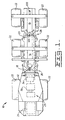
- a mobile work machine 10 having first, second, and third consecutively pivotally connected articulated steered machine sections 12,14,16 is shown.
- the first and second machine sections 12,14 are pivotal about a first elevationally oriented axis 18 and the second and third machine sections 14,16 are pivotal about a second elevational axis 20.
- the mobile work machine 10 is shown as a forwarder used in tree harvesting applications, however, other mobile work machines 10 having pivotally connected sections are considered equivalents and within the scope of the invention.
- the mobile work machine 10 has a plurality of ground engaging wheels 22, one pair connected to each of the sections, and a prime mover 24 connected to deliver motive power to the ground engaging wheels 22 in any suitable manner, for example, by an hydraulic wheel motor drive system.
- a steering system 25 includes a first pair of steering jacks 26 pivotally connected in a conventional manner between the first and second sections 12,14 and a second pair of steering jacks 28 pivotally connected in a conventional manner between the second and third sections 14,16.
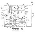
- the steering jacks 26,28 each have (Fig.6) a rod end 30, and a head end 32 and are extensibly movable in response to the application of pressurized fluid flow to the rod and/or head ends.
- the first pair of steering jacks 26 are effective to cause the first and second machine sections to pivot relative to each other about the first elevational axis 18.
- the second pair of steering jacks 28 are effective to cause the second and third machine sections 14,16 to pivot relative to each other about the second elevational axis 20. This relative controlled pivotal movement (articulation) of the first and second machine sections 12,14, and second and third machine sections 14,16 steers the machine 10 and is often referred to as articulated steering.
- a fluid control system 34 of the steering system 25 is connected to the first and second pairs-of fluid operated jacks 26,28 and actuatable to selectively direct pressurized fluid flow to the fluid operated jacks 26,28.
- the fluid control system 34 includes a pump 36, a reservoir 38 and first and second electrically operated control valves 40,42.
- the first and second control valves 40,42 are preferably infinitely variable and movable from a neutral position 44 to a selective one of first and second fluid directing positions 46,48.
- the first electrically operated control valve 40 is connected to communicate fluid flow between the first pair of fluid operated jacks 26, the pump 36 and the reservoir 38.
- the second electrically operated control valve 42 is connected to communicate fluid flow between the second pair of fluid operated jacks 28, the pump 36 and the reservoir 38.
- the first control valve 40 is connected to the head end 32 of a first jack 50 of the first pair of jacks 26 and to the rod end 30 of a second jack 52 of the first pair of jacks 26 by a conduit 54.
- the first control valve 40 is also connected to the rod end 30 of the first jack 50 and to the head end 32 of the second jack 52 by a conduit 56.
- the second control valve 42 is connected to the head end 32 of a first jack 58 of the second pair of jacks 28 and to the rod end 30 of a second jack 60 of the second pair of jacks 28 by a conduit 62.
- the second control valve 42 is also connected to the rod end 30 of the first jack 58 of the second pair of jacks 28 and to the head end 32 of the second jack 60 of the second pair of jacks 28 by a conduit 64.
- the first control valve 40 delivers pressurized fluid flow from the pump 36 to the rod end 30 of first fluid operated jack 50 of the first pair 26 and to the head end 32 of the second fluid operated jack 52 of the first pair 26 at the first position 46.
- the first control valve 40 also delivers pressurized fluid flow from the pump 36 to the rod end 30 of the second fluid operated jack 52 of the first pair 26 and to the head end 32 of the first fluid operated jack 50 of the first pair 26 at the second position 48. Excess fluid flow exhausted from the first and second jacks 50,52 is directed to the reservoir 38 by way of an appropriate one of the first and second conduits 54,56 in a conventional manner.
- the second control valve 42 delivers pressurized fluid flow from the pump 36 to the rod end 30 of the first fluid operated jack 58 of the second pair 28 and to the head end 32 of a second fluid operated jack 60 of the second pair 28 at the first position 46.
- the second control valve 42 also delivers pressurized fluid flow from the pump 36 to the rod end 30 of the second fluid operated jack 60 of the second pair 28 and to the head end 32 of the first fluid operated jack 58 of the second pair 28 at the second position 48.
- the steering system 25 includes a first sensor 66 connected to the machine 10 at a location adjacent the first elevational axis 18.
- the first sensor 66 senses the actual relative steering angle position of the first and second machine sections 12,14 and delivers a corresponding first actual steering angle signal.
- a second sensor 68 of the steering system 25 is connected to the machine 10 at a location adjacent the second elevational axis 20.
- the second sensor 68 senses the actual relative steering angle position of the second and third machine sections 14,16 and delivers a corresponding second actual steering angle signal.
- the first and second sensors 66,68 are shown as analog signal producing devices, for example, a potentiometer. However, digital devices, such as, optical encoders, magnetic transducers and the like are equivalents and considered within the scope of the invention.
- the steering system 25 includes a controller 70 connected to the first and second sensors 66,68 by electrical conductors 72,74 and receives the first and second actual steering angle signals by way of the conductors 72,74.
- the controller 70 determines a desired relative steering angle position of the second and third sections 14,16 based on the first actual steering angle signal and delivers a correcting steering angle signal in response to a difference between the desired and actual relative steering angles of the second and third sections 14,16.
- the fluid control system 34 is connected to the controller 70 and is responsive to the delivery of the correcting steering angle signal to direct pressurized fluid flow to the second pair of fluid operated jacks 28 in response to the delivery of the correcting steering angle signal.
- the position to which the second control valve 42 is shifted is a function of the sense (+ or -) of the control signal being delivered.
- the controller 70 includes a computer 76 having a processor 78, a memory 80, and an I/O port 82.
- the controller 70 may also include an analog to digital (A/D) converter 84 in applications where analog signaling devices are used and where analog signals are provided to the controller 70.
- the controller 70 also includes a driver circuit 86 which is connected to the computer 76 and to the solenoids 88,90 of the first and second electrically operated control valves 40,42 by conductors 92,94.
- the driver circuit 86 is of a conventional design and responds to signals delivered from the computer 76 to actuate either one or of both of the first and second electrically operated control valves 40,42. It should be recognized that the computer 76 herein described includes equivalent discrete electronic components of any suitable arrangement capable of performing the desired logic functions in either an open or closed loop.
- the processor 78 receives the first and second steering angle signals, and based on the first actual steering angle signal, determines the desired relative steering angle of the second and third machine sections 14,16. This determination is made in accordance with preprogrammed instructions and information 96 stored in memory 80. Information 96 includes data, maps, look-up tables and the like.
- the processor 78 compares the desired relative steering angle of the second and third machine sections 14,16 with the actual relative steering angle of the second and third machine sections 14,16 and delivers the correcting steering angle signal in response to the difference between the desired and actual relative steering angle being greater than a preselected amount.
- the preselected amount is an accepted error and tolerance determined either mathematically or empirically and considers factors such as speed of machine operation, terrain and other operation parameters.
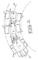
- a predetermined optimum turning arc 98 is shown for a given machine 10 configuration and size.
- the radius of the arc is determined as a function of the relative steering angle (turning radius) of the first and second machine sections 12,14.
- the relative steering angle of the second and third machine sections 14,16 is based on the turning angle of the first and second machine sections.
- the correcting steering angle signal is delivered to the driver 86. This causes actuation of the second electrically operated control valve 42 based on the correcting steering angle signal.
- the driver circuit 86 is connected to solenoids 88,90 of the first and second electrically operated control valves 40,42 by electrical conductors 92,94.
- the solenoids 88,90 respond to electrical energy delivered by the driver circuit 86 and shift the first and second valves 40,42 to appropriate ones of the first and second positions 46,48.
- the second electrically operated control valve 42 is shifted to one of the first and second positions 46,48 in response to the delivery of the correcting steering angle signal.
- the controller 70 responds and causes the driver circuit 86 to deliver a steering control signal to shift one or both of the first and second electrically operated control valves 40,42 to an appropriate one of the first and second positions 46,48.
- the steering selector device 102 is shown as an analog device, for example, a potentiometer connected to the A/D converter 84. It is to be understood that digital devices of any appropriate type, for example, an encoder, a magnetic device or the like may be substituted therefor without departing from the sprit of the invention.
- a steering mode switch 106 of the input arrangement 101 is connected to the controller 70 by a conductor 108.
- the steering mode switch 106 is movable between a first steering mode position at which the controller 70 is conditioned to block the passing of a steering control signal to the second electrically operated control valve 42 and a second steering mode position at which the controller 70 is conditioned to pass the steering control signal to the second electrically operated control valve 42.
- the steering mode switch 106 provides the capability of selecting either relative pivotal steering of only the first and second pivotally connected machine sections 12,14 or of both the first and second 12,14, and second and third 14,16 pivotally connected machine sections.
- the previously discussed steering selector device 102 may be movable to other positions at which steering signals are delivered to the controller 70 to control the second control valve 42 independently of the first control valve 40 and facilitate preliminary positioning of the third machine section 16 relative to the second machine section 14.
- An automatic-manual mode switch 110 is connected to the controller 70 by electrical conductor 112.
- the automatic-manual mode switch 110 is movable between an automatic mode position at which the correcting steering angle signal is free to pass from the controller 70 and a manual mode position at which the correcting steering angle signal is blocked from passing from the controller 70.
- the automatic-manual mode switch 110 delivers either an enabling or disabling signal to the controller 70 depending on the position selected.
- actuation of the second steering jacks 28 by the steering selector 102 is prevented at the controller 70.
- an electrically operated float valve 114 is connected to the reservoir 38, the second pair of fluid operated jacks 28, and the controller 70.
- the float valve 114 has a float position 116 at which the head and rod ends 32,30 of the second pair of fluid operated steering jacks 28 is connected to the reservoir 38.
- the float valve 114 also has an open position 118 at which fluid flow is freely delivered between the second electrically operated control valve 42 and the second pair of fluid operated steering jacks 28.
- the float valve 114 has a solenoid 120 and is spring biased to the open position 118.
- the solenoid 120 of the float valve 114 is connected to the driver 86 by an electrical conductor 122 and the float valve 114 is movable to the float position in response to receiving an electrical signal from the controller 70.
- a float switch 124 is connected to the controller 70 by an electrical conductor 126.
- the float switch 124 is movable between a first position at which a float signal is delivered to the controller 70 and a second position at which the float signal is blocked from the controller 70.
- the float valve 114 moves to the float position 116 in response to the float switch 124 being at the first position.
- the controller 70 delivers an electrical signal to the float valve 114 and moves the float valve 114 to the float position 116 in response to the float switch 124 being at the first position.
- the controller 70 disables the passing of a steering control signal to the second electrically operated control valve 42 in response to the float switch 124 being at the first position.
- the controller 70 also prevents the passing of the correcting steering angle signal to the second electrically operated control valve 42 in response to the float switch 124 being at the first position.
- the machine operator simply selects the mode of steering desired for the particular work application and uses the steering selector 102 to steer the machine over the underlying terrain.
- the operator is interested in having single articulated joint steering about the first elevational axis 18.
- the operator simply places the steering mode switch 106 at the first position. This conditions the controller 70 to block steering control signals to the second electrically operated steering valve 42 and deliver steering control signals to only the first electrically operated control valve 40.
- controlled steering occurs only about the first elevational axis 18 and between the first and second machine sections 12,14.
- the machine operator desires controlled steering of all the machine sections 12,14,16, pivotal movement about both the first and second elevational axes 18,20. This is achieved simply by placing the steering mode switch 106 at the second position. Input from the selector 102 is then processed by the controller 70 and delivered to control both the first and second electrically operated control valves 40,42.
- the machine operator is interested in enabling the third machine section 16 to simply follow the second machine section 14 with a preselected amount of restriction to free movement.
- the operator simply places the float switch 124 at the first position. This results in the controller 70 delivering a float signal to the float valve 114 and moving the float valve to the float position 116.
- the second pair of fluid operated jacks 28 are open to the reservoir 38 and free to extend and retract with the preselected amount of resistance.
- An automatic mode of operation of the steering system 25 is provided.
- the optimum steering angle of the second and third machine sections 14,16 based on the actual steering angle of the first and second machine sections 12,14 is determined.
- the fluid control system 34 articulates the second and third machine sections 14,16 to the optimum steering angle position.
- the operator simply moves the automatic-manual mode switch 110 to the automatic mode position.
- the computer 76 based on information from the first and second sensors 66,68, processes the steering angle position information in accordance with the preprogrammed instructions, determines the desired (optimum) relative steering angle of the second and third machine sections 14,16 based on the relative steering angle of the first and second machine sections 12,14, and delivers the correcting steering angle signal to the second electrically operated control valve 42.
- the second control valve 42 shifts to the appropriate one of the first and second positions 46,48, as determined by the sense of the signal, in response to there being a difference between the actual relative steering angle of the second and third machine sections and the desired steering angle of the second and third machine sections 14,16.
- the second pair of fluid operated steering jacks 28 relatively moves the second and third machine sections 14,16 in response to fluid flow directed by the second control valve 42.
- the controller 70 disables the passing of a steering control signal to the second electrically operated control valve 42 when the float switch 124 is at the first position, and disables the passing of the correcting steering angle signal to the second electrically operated control valve 42 in response to the float switch 124 being at the first position.
Landscapes
- Engineering & Computer Science (AREA)
- Chemical & Material Sciences (AREA)
- Combustion & Propulsion (AREA)
- Transportation (AREA)
- Mechanical Engineering (AREA)
- Operation Control Of Excavators (AREA)
- Steering Control In Accordance With Driving Conditions (AREA)
Description
Excess fluid flow exhausted from the first and
Claims (15)
- A steering system (25) for a mobile machine (10), having first, second and third consecutively connected relatively pivotal machine sections (12,14,16), a first pair of fluid operated steering jacks (26) connected between said first and second machine sections (12,14) and a second pair of fluid operated steering jacks (28) connected between said second and third machine sections (14,16), said first and second pair of steering jacks (26,28) being extensibly movable to pivot said first, second and third relatively pivotal machine sections (12,14,16), characterized in that the steering system comprises
a first sensor (66) connected to said machine (10), said first sensor (66) sensing the actual relative steering angle position of the first and second machine sections (12,14) and delivering a corresponding first actual steering angle signal;
a second sensor (68) connected to said machine (10), said second sensor (68) sensing the actual relative steering angle position of the second and third machine sections (14,16) and delivering a corresponding second actual steering angle signal;
a controller (70) connected to the first and second sensors (66,68), said controller (70) receiving said first and second actual steering angle signals, determining a desired relative steering angle position of the second and third sections (14,16) based on the first actual steering angle signal, and delivering a correcting steering angle signal in response to a difference between the desired and actual relative steering angles of the second and third sections (14,16). - The steering system (25), as set forth in claim 1, including:a fluid control system (34) connected to said first and second pairs of fluid operated jacks (26,28) and being actuatable to selectively direct pressurized fluid flow to said fluid operated jacks (26, 28) ;said fluid control system (34) being connected to the controller (70) and directing pressurized fluid flow to the second pair of fluid operated jacks (28) in response to receiving the correcting steering angle signal.
- The steering system (25), as set forth in claim 2, wherein said controller (70) includes a processor (78) and a memory (80), said processor (78) receiving said first and second actual steering angle signals, and based on the first actual steering angle signal, selecting from one of a map and a look-up table stored in the memory (80) the desired relative steering angle of the second and third machine sections (14,16).
- The steering system (25), as set forth in claim 3, wherein said processor (70) comparing the desired relative steering angle of the second and third machine sections (14,16) with the actual relative steering angle of the second and third machine sections (14,16) and delivering said correcting steering angle signal in response to the difference between the desired and actual relative steering angle being greater than a preselected amount.
- The steering system (25), as set forth in claim 2, wherein said first and second pairs of fluid operated jacks (26,28) each have a head end (32) and a rod end (30) and said fluid control system (25) including:a pump (36);a first electrically operated control valve (40) connected to the pump (36) and the first pair of fluid operated jacks (26); anda second electrically operated control valve (42) connected to the pump (36), the second pair of fluid operated jacks (28), and the controller (70) ;said first control valve (40) being movable to a first position at which pressurized fluid flow is directed from the pump (36) to the rod end (30) of a first of the fluid operated jacks (26,28) of the first pair and to the head end (32) of a second fluid operated jack (28) of said first pair (50), and to a second position at which pressurized fluid flow is directed from the pump (36) to the rod end (30) of the second fluid operated jack (28) of the first pair (50) and to the head end (32) of the first fluid operated jack (26) of the first pair (50); andsaid second control valve (42) being movable to a first position at which pressurized fluid flow is directed from the pump (36) to the rod end (30) of a first of the fluid operated jacks (58) of the second pair (28) and to the head end (32) of a second fluid operated jack (60) of said second pair (28), and movable to a second position at which pressurized fluid flow is directed from the pump (36) to the rod end (30) of the second fluid operated jack (60) of the second pair (28) and to the head end (32) of the first fluid operated jack (58) of the second pair (28), said second control valve (42) being shifted to one of the first and second positions in response to receiving said correcting steering angle signal.
- The steering system (25), as set forth in claim 5, including a steering selector device (102) connected to said first and second electrically operated control valves (40,42) and being movable to selectively controllably move the first and second electrically operated control valves (40,42) between said first and second positions.
- The steering system (25), as set forth in claim 6, wherein a steering control signal being delivered to at least one of the first and second electrically operated control valves (26,28) in response to movement of the steering selector device (102).
- The steering system (25), as set forth in claim 7, wherein said steering selector (102) being connected to the controller (70) and delivering a steering command signal in response to movement thereof, said controller (70) delivering a steering control signal to one of the first and second electrically operated control valves (40,42) in response to receiving the steering command signal.
- The steering system (25), as set forth in claim 8, including an automatic-manual mode switch (110) connected to said controller (70) and being movable between an automatic mode position at which the correcting steering angle signal is free to pass from said controller (70) and a manual mode position at which the correcting steering angle signal is blocked at said controller (70).
- The steering system (25), as set forth in claim 8, including a steering mode switch (106) connected to the controller (70) and movable between a first steering mode position at which the controller (70) is conditioned to block the passing of a steering control signal to the second electrical control valve (42) and a second steering mode position at which the controller (70) is conditioned to pass the steering control signal to the second electrically operated control valve (42).
- The steering system (25), as set forth in claim 8, including:a reservoir (38) ;an electrically operated float valve (114) connected to said reservoir (38), said second pair of fluid operated jacks (28), and said controller (70), said electrically operated float valve (114) having a float position at which the head and rod ends (32,30) of the second pair of fluid operated steering jacks (28) are connected to said reservoir (38), said float valve (114) and being selectively movable to the float position;a float switch (124) connected to the controller (70) and movable between a first position at which a float signal is delivered to the controller (70) and a second position at which the float signal is blocked from the controller (70), said float valve (114) moving to the float position in response to the float switch (124) being at the first position.
- The steering system (25), as set forth in claim 11, wherein said controller (70) disabling the passing of a steering control signal to the second electrically operated control valve (42) in response to said float switch (124) being at the first position.
- The steering system (25), as set forth in claim 11, wherein said controller (70) disabling the passing of the correcting steering angle signal to the second electrically operated control valve (42) in response to the float switch (129) being at the first position.
- The steering system (25), as set forth in claim 4 wherein said first and second sensors (66,68) are encoders and said first and second actual steering angle signals are digital signals.
- The steering system (25), as set forth in claim 4 wherein said first and second sensors (66,68) are potentiometers and said signals are analog signals.
Applications Claiming Priority (3)
| Application Number | Priority Date | Filing Date | Title |
|---|---|---|---|
| US916864 | 1997-08-22 | ||
| US08/916,864 US6016885A (en) | 1997-08-22 | 1997-08-22 | Steering system |
| PCT/EP1998/005307 WO1999010221A1 (en) | 1997-08-22 | 1998-08-20 | Steering system |
Publications (2)
| Publication Number | Publication Date |
|---|---|
| EP0932544A1 EP0932544A1 (en) | 1999-08-04 |
| EP0932544B1 true EP0932544B1 (en) | 2003-05-28 |
Family
ID=25437952
Family Applications (1)
| Application Number | Title | Priority Date | Filing Date |
|---|---|---|---|
| EP98946395A Expired - Lifetime EP0932544B1 (en) | 1997-08-22 | 1998-08-20 | Steering system |
Country Status (6)
| Country | Link |
|---|---|
| US (2) | US6016885A (en) |
| EP (1) | EP0932544B1 (en) |
| AU (1) | AU738729B2 (en) |
| CA (1) | CA2265680C (en) |
| DE (1) | DE69815053T2 (en) |
| WO (1) | WO1999010221A1 (en) |
Families Citing this family (28)
| Publication number | Priority date | Publication date | Assignee | Title |
|---|---|---|---|---|
| US6016885A (en) * | 1997-08-22 | 2000-01-25 | Caterpillar Inc. | Steering system |
| US6339917B1 (en) * | 1998-03-18 | 2002-01-22 | Ben N. Dillon | Articulated combine |
| US6206118B1 (en) * | 1998-09-25 | 2001-03-27 | Case Corporation | Articulated work vehicle |
| US6213490B1 (en) * | 1998-09-25 | 2001-04-10 | Case Corporation | Work vehicle with nested steering |
| US6167982B1 (en) * | 1998-12-11 | 2001-01-02 | Ben N. Dillon | Steering system for an articulated tracked combine |
| US6170848B1 (en) * | 1998-12-22 | 2001-01-09 | Joy Mm Delaware, Inc. | System and related method for steering an articulated train |
| US6749814B1 (en) | 1999-03-03 | 2004-06-15 | Symyx Technologies, Inc. | Chemical processing microsystems comprising parallel flow microreactors and methods for using same |
| DE19963344C1 (en) * | 1999-12-27 | 2001-09-20 | Sauer Danfoss Nordborg As Nord | Method for steering a vehicle |
| ATE314242T1 (en) * | 2000-10-30 | 2006-01-15 | John Deere Forestry Oy | CHASSIS CONSTRUCTION FOR A FOREST MACHINE |
| US6574539B1 (en) * | 2000-12-20 | 2003-06-03 | Visteon Global Technologies, Inc. | Steering wheel torque-based detection of misalignment of a vehicle's steering system |
| DE10065551B4 (en) * | 2000-12-28 | 2007-11-08 | Sauer-Danfoss Holding Aps | Steering system for a vehicle |
| DE10065552C1 (en) * | 2000-12-28 | 2002-04-18 | Sauer Danfoss Nordborg As Nord | Steering of vehicle involves correcting second steering device, especially articulated steering device, when it moves out of dead zone and first, especially wheel, steering device activated |
| DE10100775A1 (en) * | 2001-01-10 | 2002-07-11 | Deere & Co | Steerable axles for articulated vehicle are joined by vertical hinge axle and allowed to pivot relative to each other by controller and steerable axles are likewise under influence of controller |
| US6292094B1 (en) * | 2001-01-16 | 2001-09-18 | General Motors Corporation | Vehicle-trailer backing-up control system with vehicle rear wheel steering |
| US7412315B2 (en) * | 2002-08-30 | 2008-08-12 | Timberjack, Inc. | Steering system for articulated vehicles |
| US6999856B2 (en) * | 2003-08-28 | 2006-02-14 | General Motors Corporation | Trailer tongue length estimation using a trailer yaw rate sensor |
| SE526740C2 (en) * | 2003-11-14 | 2005-11-01 | Lennart Lundstroem | Electric propulsion vehicle |
| DE202004015747U1 (en) * | 2004-10-12 | 2005-01-27 | Rainer, Johann, Dipl.-Ing. (FH) | Two-stage steering axle concept for harvesters |
| US20070246288A1 (en) * | 2006-04-24 | 2007-10-25 | Mather Daniel T | Dual force hydraulic steering system for articulated work machine |
| US7743869B2 (en) * | 2006-04-25 | 2010-06-29 | Listerhill Total Maintenance Center LLC | Mining utility transport vehicle |
| CA2588161C (en) * | 2007-05-09 | 2014-10-28 | Prairie Machine & Parts Mfg. (1978) Ltd. | Steering system and method for train of wheeled vehicles |
| US7686320B1 (en) * | 2007-05-23 | 2010-03-30 | Mcghie James R | Steering system for a tractor and trailer |
| GB0810643D0 (en) * | 2008-06-11 | 2008-07-16 | Firth Charles B | Mine detonating apparatus |
| US9062940B2 (en) | 2008-06-11 | 2015-06-23 | Charles Basil Firth | Mine detonating apparatus |
| US9308936B2 (en) | 2011-05-06 | 2016-04-12 | Volvo Construction Equipment Ab | Method for controlling a working machine, and a working machine |
| US9296566B2 (en) * | 2011-05-19 | 2016-03-29 | Barbara Anne Finatzer | Conveyor system |
| DE202014003831U1 (en) * | 2014-05-07 | 2015-08-10 | Peter Bohnet | Low loader trailer |
| WO2018049475A1 (en) | 2016-09-15 | 2018-03-22 | Terex Australia Pty Ltd | Crane counterweight and suspension |
Family Cites Families (19)
| Publication number | Priority date | Publication date | Assignee | Title |
|---|---|---|---|---|
| US4153265A (en) * | 1975-06-05 | 1979-05-08 | Owens-Illinois, Inc. | Off-road vehicle |
| US4019603A (en) * | 1975-12-24 | 1977-04-26 | Caterpillar Tractor Co. | Understeer vehicle steering system |
| GR79630B (en) * | 1982-08-18 | 1984-10-31 | Falkenried Fahrzeug Gmbh | |
| HU203058B (en) * | 1984-02-24 | 1991-05-28 | Autoipari Kutato Fejlesztoe | Hydraulic articulation-angle influencing apparatus for articulated vehicle |
| FR2587962A1 (en) * | 1985-09-30 | 1987-04-03 | Martinet Simon | DEVICE FOR SERVICING THE DIRECTION OF AN ARTICULATED VEHICLE |
| SE462277B (en) * | 1988-10-05 | 1990-05-28 | Vme Ind Sweden Ab | HYDRAULIC CONTROL SYSTEM |
| US5035439A (en) * | 1989-05-02 | 1991-07-30 | Petrillo Patrick G | Method and means for providing rear steerability in a trailer assembly |
| JPH0345471A (en) * | 1989-07-14 | 1991-02-27 | Komatsu Ltd | Handle position correction device for fully hydraulic steering system |
| WO1991014610A1 (en) * | 1990-03-20 | 1991-10-03 | Skogsjan Invest Ab | A device in vehicles |
| US5289892A (en) * | 1990-09-26 | 1994-03-01 | Nissan Diesel Motor Co., Ltd. | Steerable trailer and steering apparatus of combination vehicle |
| US5579228A (en) * | 1991-05-21 | 1996-11-26 | University Of Utah Research Foundation | Steering control system for trailers |
| US5244226A (en) * | 1991-09-23 | 1993-09-14 | Bergh C John | Trailer and steerable wheels therefor |
| US5247442A (en) * | 1991-09-25 | 1993-09-21 | Brigham Young University | Vehicular steering system for reverse paths |
| CA2077039C (en) * | 1992-08-27 | 1997-05-20 | Maurice Demong | Steering system for plurality of vehicles |
| US5607028A (en) * | 1993-11-29 | 1997-03-04 | Braun; Eric E. | All-wheel steering system |
| US5417299A (en) * | 1993-11-29 | 1995-05-23 | Oshkosh Truck Corporation | All-wheel steering systems |
| US5489005A (en) * | 1994-11-23 | 1996-02-06 | Caterpillar Inc. | Electro-hydraulic steering system |
| US5520262A (en) * | 1995-04-28 | 1996-05-28 | Caterpillar Inc. | Electrohydraulic steering system |
| US6016885A (en) * | 1997-08-22 | 2000-01-25 | Caterpillar Inc. | Steering system |
-
1997
- 1997-08-22 US US08/916,864 patent/US6016885A/en not_active Expired - Lifetime
-
1998
- 1998-08-20 CA CA002265680A patent/CA2265680C/en not_active Expired - Fee Related
- 1998-08-20 EP EP98946395A patent/EP0932544B1/en not_active Expired - Lifetime
- 1998-08-20 AU AU93452/98A patent/AU738729B2/en not_active Ceased
- 1998-08-20 WO PCT/EP1998/005307 patent/WO1999010221A1/en not_active Ceased
- 1998-08-20 DE DE69815053T patent/DE69815053T2/en not_active Expired - Fee Related
-
1999
- 1999-12-22 US US09/470,371 patent/US6129170A/en not_active Expired - Lifetime
Also Published As
| Publication number | Publication date |
|---|---|
| AU9345298A (en) | 1999-03-16 |
| US6129170A (en) | 2000-10-10 |
| DE69815053T2 (en) | 2004-04-08 |
| CA2265680C (en) | 2007-03-20 |
| US6016885A (en) | 2000-01-25 |
| DE69815053D1 (en) | 2003-07-03 |
| AU738729B2 (en) | 2001-09-27 |
| WO1999010221A1 (en) | 1999-03-04 |
| EP0932544A1 (en) | 1999-08-04 |
| CA2265680A1 (en) | 1999-03-04 |
Similar Documents
| Publication | Publication Date | Title |
|---|---|---|
| US6016885A (en) | Steering system | |
| US6827176B2 (en) | Vehicle with offset extendible axles and independent four-wheel steering control | |
| US4802545A (en) | Steering control system for articulated vehicle | |
| US5489005A (en) | Electro-hydraulic steering system | |
| US7520362B2 (en) | Steering system for crane | |
| US6164406A (en) | Multiple-axle steering system for agricultural harvesting machines | |
| US4565257A (en) | Multi-mode steering system | |
| US4144946A (en) | Hydraulic priority circuit | |
| US7853380B2 (en) | Steering system having multiple strategies and variable deadzone | |
| US4771851A (en) | Steering control system for articulated vehicle | |
| KR19980081199A (en) | Multi-axle steering system | |
| US6793036B1 (en) | Working vehicle with transverse system | |
| JPH04870B2 (en) | ||
| EP0597655A1 (en) | Four-wheel steering | |
| EP1532035B1 (en) | A vehicle and a method for controlling steering thereof | |
| GB2128947A (en) | Vehicle steering system | |
| JP2789007B2 (en) | Interplane turning mechanism for aerial work vehicles | |
| JPS633711A (en) | Running control apparatus of automatic running working vehicle | |
| JP2822576B2 (en) | Four-wheel steering control device | |
| CA1043706A (en) | Understeer vehicle steering system | |
| JP2789006B2 (en) | Steering mechanism for aerial work vehicles | |
| US20260070610A1 (en) | Working vehicle steering system | |
| GB2249289A (en) | Vehicle, eg mower, with skid steering and articulated steering | |
| JP3038771B2 (en) | Four-wheel steering control device | |
| JPH05193515A (en) | Self-propelled vehicle |
Legal Events
| Date | Code | Title | Description |
|---|---|---|---|
| PUAI | Public reference made under article 153(3) epc to a published international application that has entered the european phase |
Free format text: ORIGINAL CODE: 0009012 |
|
| 17P | Request for examination filed |
Effective date: 19990414 |
|
| AK | Designated contracting states |
Kind code of ref document: A1 Designated state(s): DE FI FR SE |
|
| RAP1 | Party data changed (applicant data changed or rights of an application transferred) |
Owner name: CATERPILLAR SARL |
|
| GRAH | Despatch of communication of intention to grant a patent |
Free format text: ORIGINAL CODE: EPIDOS IGRA |
|
| GRAH | Despatch of communication of intention to grant a patent |
Free format text: ORIGINAL CODE: EPIDOS IGRA |
|
| GRAA | (expected) grant |
Free format text: ORIGINAL CODE: 0009210 |
|
| AK | Designated contracting states |
Designated state(s): DE FI FR SE |
|
| PG25 | Lapsed in a contracting state [announced via postgrant information from national office to epo] |
Ref country code: FR Free format text: LAPSE BECAUSE OF FAILURE TO SUBMIT A TRANSLATION OF THE DESCRIPTION OR TO PAY THE FEE WITHIN THE PRESCRIBED TIME-LIMIT Effective date: 20030528 |
|
| REF | Corresponds to: |
Ref document number: 69815053 Country of ref document: DE Date of ref document: 20030703 Kind code of ref document: P |
|
| REG | Reference to a national code |
Ref country code: SE Ref legal event code: TRGR |
|
| PLBE | No opposition filed within time limit |
Free format text: ORIGINAL CODE: 0009261 |
|
| STAA | Information on the status of an ep patent application or granted ep patent |
Free format text: STATUS: NO OPPOSITION FILED WITHIN TIME LIMIT |
|
| 26N | No opposition filed |
Effective date: 20040302 |
|
| EN | Fr: translation not filed | ||
| PGFP | Annual fee paid to national office [announced via postgrant information from national office to epo] |
Ref country code: DE Payment date: 20080829 Year of fee payment: 11 |
|
| PGFP | Annual fee paid to national office [announced via postgrant information from national office to epo] |
Ref country code: FI Payment date: 20080821 Year of fee payment: 11 |
|
| PGFP | Annual fee paid to national office [announced via postgrant information from national office to epo] |
Ref country code: SE Payment date: 20080808 Year of fee payment: 11 |
|
| PG25 | Lapsed in a contracting state [announced via postgrant information from national office to epo] |
Ref country code: FI Free format text: LAPSE BECAUSE OF NON-PAYMENT OF DUE FEES Effective date: 20090820 |
|
| PG25 | Lapsed in a contracting state [announced via postgrant information from national office to epo] |
Ref country code: DE Free format text: LAPSE BECAUSE OF NON-PAYMENT OF DUE FEES Effective date: 20100302 |
|
| PG25 | Lapsed in a contracting state [announced via postgrant information from national office to epo] |
Ref country code: SE Free format text: LAPSE BECAUSE OF NON-PAYMENT OF DUE FEES Effective date: 20090821 |