EP0932499B1 - Compact disc tack curing assembly line - Google Patents
Compact disc tack curing assembly line Download PDFInfo
- Publication number
- EP0932499B1 EP0932499B1 EP98908946A EP98908946A EP0932499B1 EP 0932499 B1 EP0932499 B1 EP 0932499B1 EP 98908946 A EP98908946 A EP 98908946A EP 98908946 A EP98908946 A EP 98908946A EP 0932499 B1 EP0932499 B1 EP 0932499B1
- Authority
- EP
- European Patent Office
- Prior art keywords
- disc
- adhesive
- halves
- composite
- bonding
- Prior art date
- Legal status (The legal status is an assumption and is not a legal conclusion. Google has not performed a legal analysis and makes no representation as to the accuracy of the status listed.)
- Expired - Lifetime
Links
- 239000000853 adhesive Substances 0.000 claims abstract description 29
- 230000001070 adhesive effect Effects 0.000 claims abstract description 29
- 239000002131 composite material Substances 0.000 claims abstract description 18
- 238000000034 method Methods 0.000 claims abstract description 14
- 125000006850 spacer group Chemical group 0.000 claims description 16
- 238000004519 manufacturing process Methods 0.000 claims description 13
- 238000001465 metallisation Methods 0.000 claims description 11
- 238000001746 injection moulding Methods 0.000 claims description 10
- 239000011248 coating agent Substances 0.000 claims description 3
- 238000000576 coating method Methods 0.000 claims description 3
- 238000004026 adhesive bonding Methods 0.000 claims 1
- 239000012790 adhesive layer Substances 0.000 claims 1
- 239000010410 layer Substances 0.000 claims 1
- 238000009987 spinning Methods 0.000 claims 1
- 230000003287 optical effect Effects 0.000 abstract description 6
- 238000000926 separation method Methods 0.000 abstract description 4
- 238000004886 process control Methods 0.000 abstract 1
- 239000004033 plastic Substances 0.000 description 7
- 239000011324 bead Substances 0.000 description 2
- 238000001816 cooling Methods 0.000 description 2
- 230000000694 effects Effects 0.000 description 2
- 230000033001 locomotion Effects 0.000 description 2
- 230000007246 mechanism Effects 0.000 description 2
- 239000004417 polycarbonate Substances 0.000 description 2
- 229920000515 polycarbonate Polymers 0.000 description 2
- 230000005855 radiation Effects 0.000 description 2
- 238000003892 spreading Methods 0.000 description 2
- 238000003860 storage Methods 0.000 description 2
- 206010073261 Ovarian theca cell tumour Diseases 0.000 description 1
- 230000015572 biosynthetic process Effects 0.000 description 1
- 230000007547 defect Effects 0.000 description 1
- 239000012530 fluid Substances 0.000 description 1
- 238000010438 heat treatment Methods 0.000 description 1
- 238000003475 lamination Methods 0.000 description 1
- 239000000463 material Substances 0.000 description 1
- 239000002184 metal Substances 0.000 description 1
- 239000002991 molded plastic Substances 0.000 description 1
- 239000012768 molten material Substances 0.000 description 1
- 229920000642 polymer Polymers 0.000 description 1
- 230000010076 replication Effects 0.000 description 1
- 238000006467 substitution reaction Methods 0.000 description 1
- 208000001644 thecoma Diseases 0.000 description 1
Images




Classifications
-
- B—PERFORMING OPERATIONS; TRANSPORTING
- B29—WORKING OF PLASTICS; WORKING OF SUBSTANCES IN A PLASTIC STATE IN GENERAL
- B29C—SHAPING OR JOINING OF PLASTICS; SHAPING OF MATERIAL IN A PLASTIC STATE, NOT OTHERWISE PROVIDED FOR; AFTER-TREATMENT OF THE SHAPED PRODUCTS, e.g. REPAIRING
- B29C65/00—Joining or sealing of preformed parts, e.g. welding of plastics materials; Apparatus therefor
- B29C65/78—Means for handling the parts to be joined, e.g. for making containers or hollow articles, e.g. means for handling sheets, plates, web-like materials, tubular articles, hollow articles or elements to be joined therewith; Means for discharging the joined articles from the joining apparatus
- B29C65/7841—Holding or clamping means for handling purposes
- B29C65/7847—Holding or clamping means for handling purposes using vacuum to hold at least one of the parts to be joined
-
- B—PERFORMING OPERATIONS; TRANSPORTING
- B29—WORKING OF PLASTICS; WORKING OF SUBSTANCES IN A PLASTIC STATE IN GENERAL
- B29C—SHAPING OR JOINING OF PLASTICS; SHAPING OF MATERIAL IN A PLASTIC STATE, NOT OTHERWISE PROVIDED FOR; AFTER-TREATMENT OF THE SHAPED PRODUCTS, e.g. REPAIRING
- B29C65/00—Joining or sealing of preformed parts, e.g. welding of plastics materials; Apparatus therefor
- B29C65/48—Joining or sealing of preformed parts, e.g. welding of plastics materials; Apparatus therefor using adhesives, i.e. using supplementary joining material; solvent bonding
- B29C65/4805—Joining or sealing of preformed parts, e.g. welding of plastics materials; Apparatus therefor using adhesives, i.e. using supplementary joining material; solvent bonding characterised by the type of adhesives
- B29C65/483—Reactive adhesives, e.g. chemically curing adhesives
-
- B—PERFORMING OPERATIONS; TRANSPORTING
- B29—WORKING OF PLASTICS; WORKING OF SUBSTANCES IN A PLASTIC STATE IN GENERAL
- B29C—SHAPING OR JOINING OF PLASTICS; SHAPING OF MATERIAL IN A PLASTIC STATE, NOT OTHERWISE PROVIDED FOR; AFTER-TREATMENT OF THE SHAPED PRODUCTS, e.g. REPAIRING
- B29C66/00—General aspects of processes or apparatus for joining preformed parts
- B29C66/01—General aspects dealing with the joint area or with the area to be joined
- B29C66/03—After-treatments in the joint area
- B29C66/032—Mechanical after-treatments
-
- B—PERFORMING OPERATIONS; TRANSPORTING
- B29—WORKING OF PLASTICS; WORKING OF SUBSTANCES IN A PLASTIC STATE IN GENERAL
- B29C—SHAPING OR JOINING OF PLASTICS; SHAPING OF MATERIAL IN A PLASTIC STATE, NOT OTHERWISE PROVIDED FOR; AFTER-TREATMENT OF THE SHAPED PRODUCTS, e.g. REPAIRING
- B29C66/00—General aspects of processes or apparatus for joining preformed parts
- B29C66/01—General aspects dealing with the joint area or with the area to be joined
- B29C66/05—Particular design of joint configurations
- B29C66/10—Particular design of joint configurations particular design of the joint cross-sections
- B29C66/11—Joint cross-sections comprising a single joint-segment, i.e. one of the parts to be joined comprising a single joint-segment in the joint cross-section
- B29C66/112—Single lapped joints
- B29C66/1122—Single lap to lap joints, i.e. overlap joints
-
- B—PERFORMING OPERATIONS; TRANSPORTING
- B29—WORKING OF PLASTICS; WORKING OF SUBSTANCES IN A PLASTIC STATE IN GENERAL
- B29C—SHAPING OR JOINING OF PLASTICS; SHAPING OF MATERIAL IN A PLASTIC STATE, NOT OTHERWISE PROVIDED FOR; AFTER-TREATMENT OF THE SHAPED PRODUCTS, e.g. REPAIRING
- B29C66/00—General aspects of processes or apparatus for joining preformed parts
- B29C66/40—General aspects of joining substantially flat articles, e.g. plates, sheets or web-like materials; Making flat seams in tubular or hollow articles; Joining single elements to substantially flat surfaces
- B29C66/41—Joining substantially flat articles ; Making flat seams in tubular or hollow articles
- B29C66/45—Joining of substantially the whole surface of the articles
- B29C66/452—Joining of substantially the whole surface of the articles the article having a disc form, e.g. making CDs or DVDs
-
- B—PERFORMING OPERATIONS; TRANSPORTING
- B29—WORKING OF PLASTICS; WORKING OF SUBSTANCES IN A PLASTIC STATE IN GENERAL
- B29C—SHAPING OR JOINING OF PLASTICS; SHAPING OF MATERIAL IN A PLASTIC STATE, NOT OTHERWISE PROVIDED FOR; AFTER-TREATMENT OF THE SHAPED PRODUCTS, e.g. REPAIRING
- B29C66/00—General aspects of processes or apparatus for joining preformed parts
- B29C66/70—General aspects of processes or apparatus for joining preformed parts characterised by the composition, physical properties or the structure of the material of the parts to be joined; Joining with non-plastics material
- B29C66/72—General aspects of processes or apparatus for joining preformed parts characterised by the composition, physical properties or the structure of the material of the parts to be joined; Joining with non-plastics material characterised by the structure of the material of the parts to be joined
- B29C66/723—General aspects of processes or apparatus for joining preformed parts characterised by the composition, physical properties or the structure of the material of the parts to be joined; Joining with non-plastics material characterised by the structure of the material of the parts to be joined being multi-layered
- B29C66/7232—General aspects of processes or apparatus for joining preformed parts characterised by the composition, physical properties or the structure of the material of the parts to be joined; Joining with non-plastics material characterised by the structure of the material of the parts to be joined being multi-layered comprising a non-plastics layer
- B29C66/72321—General aspects of processes or apparatus for joining preformed parts characterised by the composition, physical properties or the structure of the material of the parts to be joined; Joining with non-plastics material characterised by the structure of the material of the parts to be joined being multi-layered comprising a non-plastics layer consisting of metals or their alloys
-
- B—PERFORMING OPERATIONS; TRANSPORTING
- B29—WORKING OF PLASTICS; WORKING OF SUBSTANCES IN A PLASTIC STATE IN GENERAL
- B29D—PRODUCING PARTICULAR ARTICLES FROM PLASTICS OR FROM SUBSTANCES IN A PLASTIC STATE
- B29D17/00—Producing carriers of records containing fine grooves or impressions, e.g. disc records for needle playback, cylinder records; Producing record discs from master stencils
- B29D17/005—Producing optically read record carriers, e.g. optical discs
-
- B—PERFORMING OPERATIONS; TRANSPORTING
- B32—LAYERED PRODUCTS
- B32B—LAYERED PRODUCTS, i.e. PRODUCTS BUILT-UP OF STRATA OF FLAT OR NON-FLAT, e.g. CELLULAR OR HONEYCOMB, FORM
- B32B37/00—Methods or apparatus for laminating, e.g. by curing or by ultrasonic bonding
- B32B37/0007—Methods or apparatus for laminating, e.g. by curing or by ultrasonic bonding involving treatment or provisions in order to avoid deformation or air inclusion, e.g. to improve surface quality
-
- B—PERFORMING OPERATIONS; TRANSPORTING
- B32—LAYERED PRODUCTS
- B32B—LAYERED PRODUCTS, i.e. PRODUCTS BUILT-UP OF STRATA OF FLAT OR NON-FLAT, e.g. CELLULAR OR HONEYCOMB, FORM
- B32B37/00—Methods or apparatus for laminating, e.g. by curing or by ultrasonic bonding
- B32B37/0007—Methods or apparatus for laminating, e.g. by curing or by ultrasonic bonding involving treatment or provisions in order to avoid deformation or air inclusion, e.g. to improve surface quality
- B32B37/0015—Methods or apparatus for laminating, e.g. by curing or by ultrasonic bonding involving treatment or provisions in order to avoid deformation or air inclusion, e.g. to improve surface quality to avoid warp or curl
-
- B—PERFORMING OPERATIONS; TRANSPORTING
- B32—LAYERED PRODUCTS
- B32B—LAYERED PRODUCTS, i.e. PRODUCTS BUILT-UP OF STRATA OF FLAT OR NON-FLAT, e.g. CELLULAR OR HONEYCOMB, FORM
- B32B38/00—Ancillary operations in connection with laminating processes
- B32B38/18—Handling of layers or the laminate
- B32B38/1866—Handling of layers or the laminate conforming the layers or laminate to a convex or concave profile
-
- G—PHYSICS
- G11—INFORMATION STORAGE
- G11B—INFORMATION STORAGE BASED ON RELATIVE MOVEMENT BETWEEN RECORD CARRIER AND TRANSDUCER
- G11B7/00—Recording or reproducing by optical means, e.g. recording using a thermal beam of optical radiation by modifying optical properties or the physical structure, reproducing using an optical beam at lower power by sensing optical properties; Record carriers therefor
- G11B7/24—Record carriers characterised by shape, structure or physical properties, or by the selection of the material
- G11B7/26—Apparatus or processes specially adapted for the manufacture of record carriers
-
- B—PERFORMING OPERATIONS; TRANSPORTING
- B29—WORKING OF PLASTICS; WORKING OF SUBSTANCES IN A PLASTIC STATE IN GENERAL
- B29C—SHAPING OR JOINING OF PLASTICS; SHAPING OF MATERIAL IN A PLASTIC STATE, NOT OTHERWISE PROVIDED FOR; AFTER-TREATMENT OF THE SHAPED PRODUCTS, e.g. REPAIRING
- B29C65/00—Joining or sealing of preformed parts, e.g. welding of plastics materials; Apparatus therefor
- B29C65/48—Joining or sealing of preformed parts, e.g. welding of plastics materials; Apparatus therefor using adhesives, i.e. using supplementary joining material; solvent bonding
- B29C65/4805—Joining or sealing of preformed parts, e.g. welding of plastics materials; Apparatus therefor using adhesives, i.e. using supplementary joining material; solvent bonding characterised by the type of adhesives
- B29C65/483—Reactive adhesives, e.g. chemically curing adhesives
- B29C65/4845—Radiation curing adhesives, e.g. UV light curing adhesives
-
- B—PERFORMING OPERATIONS; TRANSPORTING
- B29—WORKING OF PLASTICS; WORKING OF SUBSTANCES IN A PLASTIC STATE IN GENERAL
- B29C—SHAPING OR JOINING OF PLASTICS; SHAPING OF MATERIAL IN A PLASTIC STATE, NOT OTHERWISE PROVIDED FOR; AFTER-TREATMENT OF THE SHAPED PRODUCTS, e.g. REPAIRING
- B29C65/00—Joining or sealing of preformed parts, e.g. welding of plastics materials; Apparatus therefor
- B29C65/48—Joining or sealing of preformed parts, e.g. welding of plastics materials; Apparatus therefor using adhesives, i.e. using supplementary joining material; solvent bonding
- B29C65/52—Joining or sealing of preformed parts, e.g. welding of plastics materials; Apparatus therefor using adhesives, i.e. using supplementary joining material; solvent bonding characterised by the way of applying the adhesive
- B29C65/521—Joining or sealing of preformed parts, e.g. welding of plastics materials; Apparatus therefor using adhesives, i.e. using supplementary joining material; solvent bonding characterised by the way of applying the adhesive by spin coating
-
- B—PERFORMING OPERATIONS; TRANSPORTING
- B29—WORKING OF PLASTICS; WORKING OF SUBSTANCES IN A PLASTIC STATE IN GENERAL
- B29C—SHAPING OR JOINING OF PLASTICS; SHAPING OF MATERIAL IN A PLASTIC STATE, NOT OTHERWISE PROVIDED FOR; AFTER-TREATMENT OF THE SHAPED PRODUCTS, e.g. REPAIRING
- B29C66/00—General aspects of processes or apparatus for joining preformed parts
- B29C66/70—General aspects of processes or apparatus for joining preformed parts characterised by the composition, physical properties or the structure of the material of the parts to be joined; Joining with non-plastics material
- B29C66/71—General aspects of processes or apparatus for joining preformed parts characterised by the composition, physical properties or the structure of the material of the parts to be joined; Joining with non-plastics material characterised by the composition of the plastics material of the parts to be joined
-
- B—PERFORMING OPERATIONS; TRANSPORTING
- B29—WORKING OF PLASTICS; WORKING OF SUBSTANCES IN A PLASTIC STATE IN GENERAL
- B29L—INDEXING SCHEME ASSOCIATED WITH SUBCLASS B29C, RELATING TO PARTICULAR ARTICLES
- B29L2017/00—Carriers for sound or information
- B29L2017/001—Carriers of records containing fine grooves or impressions, e.g. disc records for needle playback, cylinder records
- B29L2017/003—Records or discs
- B29L2017/005—CD''s, DVD''s
-
- B—PERFORMING OPERATIONS; TRANSPORTING
- B32—LAYERED PRODUCTS
- B32B—LAYERED PRODUCTS, i.e. PRODUCTS BUILT-UP OF STRATA OF FLAT OR NON-FLAT, e.g. CELLULAR OR HONEYCOMB, FORM
- B32B38/00—Ancillary operations in connection with laminating processes
- B32B38/18—Handling of layers or the laminate
- B32B2038/1891—Using a robot for handling the layers
-
- B—PERFORMING OPERATIONS; TRANSPORTING
- B32—LAYERED PRODUCTS
- B32B—LAYERED PRODUCTS, i.e. PRODUCTS BUILT-UP OF STRATA OF FLAT OR NON-FLAT, e.g. CELLULAR OR HONEYCOMB, FORM
- B32B2310/00—Treatment by energy or chemical effects
- B32B2310/08—Treatment by energy or chemical effects by wave energy or particle radiation
- B32B2310/0806—Treatment by energy or chemical effects by wave energy or particle radiation using electromagnetic radiation
- B32B2310/0831—Treatment by energy or chemical effects by wave energy or particle radiation using electromagnetic radiation using UV radiation
-
- B—PERFORMING OPERATIONS; TRANSPORTING
- B32—LAYERED PRODUCTS
- B32B—LAYERED PRODUCTS, i.e. PRODUCTS BUILT-UP OF STRATA OF FLAT OR NON-FLAT, e.g. CELLULAR OR HONEYCOMB, FORM
- B32B2429/00—Carriers for sound or information
- B32B2429/02—Records or discs
Definitions
- This invention relates to the manufacture of compact optical data discs for the storage of information in the form of a high density of pits in a flat plastic disc shaped surface.
- it relates to the manufacture of such discs by the formation of a composite of two surfaces bonded to each other during the disc manufacturing process.
- apparatus for use in a disc manufacturing assembly line to assure that the resulting composite is planar after the completion of the bonding process.
- An in-line system for manufacturing a compact disc composite according to the preamble of claim 7 is for example known from JP-A-03 296 930.
- Plastic discs having a pit optical track structure are known as compact discs.
- Double sided discs in which information is recorded on two sides of such a structure formed by binding two compact discs and apparatus for playing such discs is also known, as in U.S. patents 4,903,140; 4,939,011; 5,097,465; 4,811,324.
- U.S. patents 5,284,538 and 5,378,517 it is also taught in U.S. patents 5,284,538 and 5,378,517 that it is advantageous to bring the two disc portions together at an angle in order to facilitate bonding.
- compact disc as used in this application includes any disc shaped recorded medium having pits and lands forming an optical track structure on a data information recording planar surface. Thus it includes such discs where the information stored as pits and lands is digital information, analog information, or information of a graphic or holographic nature. Examples of the different types of information storage are as follows: Digital information may be encoded into the pits and lands as pits of quantized lengths interpretable as a stream of digital data, wherein the length of each pit or land segment may be, for example, related to the number of 1's or 0's in a data stream. An example of such a system is the compact disc ("CD”) audio or video disc.
- CD compact disc
- Analog information may be encoded into the pits and lands as pit lengths that may vary over a continuum of values, wherein the length of each pit or land segment may be, for example, related to a voltage level in a desired output.
- An example of such an analog system is the laser disc video recording system.
- Graphics may be placed on the surface of a disc by employing the light reflection properties of pitted surfaces that are visible to the unaided eye.
- holographic information may be stored in a pit/land format, particularly where it is possible to vary the pit depth to create reflection interference patterns that are visible as a holographic image viewable by the unaided eye.
- the present invention relates to two layer compact disc information retrieval systems having a pit optical track structure.
- the invention relates to a method and apparatus for bonding together two compact half discs or one half disc and a support or fill in half disc to form a double layered disc in an assembly line manufacturing system.
- the invention is specifically concerned with the manufacture of 0.6 mm thick optical discs produced by an injection molding machine for lamination to either blank or information side similar discs.
- Injection molding methods and apparatus are known in the art. Injection molding can be generally described as a replication process in which a molten material (usually a polymer) is injected into a cavity and after cooling forms the geometry of the cavity.
- the present invention involves a combination of improvements of the assembly line process for the manufacture of compact discs. It involves improvements in several stations.
- the present invention is an in-line system for fabricating a double layered compact disc by bonding together two surfaces, at least one of which is information bearing, separately referred to as half discs.
- the system comprises stages for the injection molding of the disc surfaces and their metallization, an adhesive dispensing and distributing station including a unique spacer chuck, a preliminary tacking station, and a final bonding station comprising a unique disc deforming jig .
- the spacer chuck is used to maintain a separation between the two half disc surfaces subsequent to the application of an ultra-violet light curable adhesive to one surface and prior to its spreading across the disc surface.
- This separation chuck engages the discs at their central openings. It has a detent past which the lower disc half is pushed, while the upper disc half is placed on the chuck to lie against the upper surface of the detent.
- the chuck enables a rapid and careful timing of the series of steps in which the adhesive is contacted by the second surface, spread, and tack cured.
- the assemblage of discs at all stations is positioned by robotic mechanisms.
- Tack curing is achieved by a low intensity exposure to ultra-violet light that exposes primarily the non-data portions of the disc, i.e. the inner and outer radii that extend beyond the metallization region.
- This tack curing is a feature of the invention that allows the movement of the composite to the final curing station where the surfaces are subjected to intense heat that could tend to deform the surfaces unequally.
- a unique disc deforming jig holds the disc in a particular curved configuration so that it forms a flat surface after cooling from the bonding station temperature. By tacking down the radii as described and using the disc deforming jig, motion of the disc surfaces and the attendant distortion is avoided.
- Fig. 6 depicts a cross section of a portion of double surfaced compact disc 1 formed from an upper half surface 3 and a lower information bearing half surface 5 .
- the surface 3 may be, but need not be, information bearing.
- Each half bearing surface is formed by injection molding a polycarbonate plastic surface having a pattern of pits and lands 7 and coating the pits and lands with a metallic reflective coating 9.
- the in-line system is shown in Fig. 4, in which an injection molding station 11 injects a molten transparent polycarbonate plastic into a mold cavity, having a stamper on one face to produce a clear plastic disc 5 with pits 7 impressed on one side.
- the molded plastic disc is place in a carousel 17 which rotates to bring it to the metallization station 13 where it is lifted by a robotic arm brought into the metallization station, coated upon its pitted surface with a reflective metal layer 9 and returned to the carousel. Where the surface is not information bearing it would not require a metallization step.
- the half disc 5 travels upon disc transport belts 15 during which time it cools somewhat.
- the corresponding upper disc half 3 waits upon a spindle for assembly.
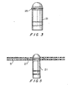
- a spacer chuck as shown in Fig. 3 is present.
- the disc half is returned from metallization by a robotic arm it is forced down from above onto the spacer chuck past the detent element 25.
- the lower disc half is moved by a robotic arm to a rotation station 23.
- the lower disc half is placed upon a spacer chuck 21 shown in detail in Fig. 3.
- a fluid dispensing arm 19 places a ring of an ultra-violet curable adhesive as the lower half disc as it is slowly rotated through a full rotation on the spacer chuck.
- the detent has a lesser height than the layer of adhesive 27 placed at an inner radius of the lower half disc.
- a robotic arm then removes the upper half disc from the spindle 20 and places it upon the spacer chuck as shown in Fig. 5, so that it does not contact the adhesive 27.
- the pair of discs is lifted by a robotic arm that reaches into the space between the spacer chuck and the central hole in the two disc surfaces to lift the disc while maintaining the separation established by the detent in the spacer chuck.
- the space between the chuck and the central hole is accessible because the detent does not extend around the entire circumference of the spacer chuck.
- the combination is lifted to one of two spin stations 24 where the upper surface comes into contact with the adhesive and the sandwich of discs and adhesive is rapidly spun to spread the adhesive to form the thin layer 4 shown in Fig. 6. (Note that the dimensions shown in Fig.
- the composite is then lifted to a second carousel 18 where it is tack cured by exposing the composite to ultra-violet light of low intensity adjusted so that primarily the inner and outer circumferences of the disc halves are bonded.
- This may be simply accomplished because the compact disc, as shown in Fig. 7, has a metallization layer that does not extend to either the internal or external radii of the disc. Since the metallization of the disc has been accomplished prior to this exposure, it is sufficient to bathe the entire disc in ultra-violet radiation and rely upon the shielding by the metallization layer to effect the tacking of the surfaces together at their inner and outer circumferences. Tack curing is effectively limited to the inner and outer regions 29 and 31.
- the disc composite is then engaged by the disc deforming jig 33 shown in Fig. 1.
- the jig has an inner ring of suction feet 35 and outer ring of suction feet 37 that hold the disc at inner and outer radii.
- the rings of suction feet are moveable with respect to each other by raising the central potion 34 to which the inner suction feet are attached, with respect to the outer ring 39.
- the adjustment is made by a screw mechanism engaged by the knob 37 seen for example in Fig. 2A.
- the adjustment results in a raising and lowering of the suction cup feet that bear against the disc surface.
- a vacuum is present through channels leading to the feet to engage the disc and to force it firmly against the suction cup feet so that the adjustment in position effects the deformation of the disc resulting in planarity
- the disc deforming jig 33 holds the disc flat as in Fig. 2A or deformed either positively as in Fig. 2B or negatively as in Fig. 2C during the final curing stage occurring at curing station.
- the jig is adjusted to compensate for any overall non-planarity that the preceding process steps were unable to eliminate.
- the jig is not adjusted on a disc by disc basis, but is adjusted to compensate for the average tilt resulting from the operation of the assembly line.
- the composite While engaged by the jig the composite is exposed to sufficient ultra-violet light to cure the adhesive. Although this requires the ultra-violet light to pass through the metallic layer, that is accomplished by using a high intensity ultra-violet source. In this manner a flat composite is formed even though substantial heating of the composite may occur.
Landscapes
- Engineering & Computer Science (AREA)
- Mechanical Engineering (AREA)
- Quality & Reliability (AREA)
- Manufacturing & Machinery (AREA)
- Chemical & Material Sciences (AREA)
- Chemical Kinetics & Catalysis (AREA)
- General Chemical & Material Sciences (AREA)
- Manufacturing Optical Record Carriers (AREA)
- Heating, Cooling, Or Curing Plastics Or The Like In General (AREA)
- Adhesives Or Adhesive Processes (AREA)
- Curing Cements, Concrete, And Artificial Stone (AREA)
- Polyurethanes Or Polyureas (AREA)
Abstract
Description
Claims (8)
- A method for controlling the planarity of a compact disc formed by bonding two half disc surfaces, comprising(a) preparing the half disc surfaces (3, 5) by injection molding and metallization of at least one half surface,(b) placing a ring of adhesive on an inner radius of one of the disc halves,(c) locating both disc halves on a spacer chuck (21) so that the disc halves (3, 5) are separated,(d) removing the disc halves (3, 5) from the spacer chuck (21) to a station where the disc halves may both contact the adhesive,(e) spinning the disc halves to spread the adhesive to form a layer (27) between the said disc halves (3, 5),(f) tack curing the adhesive,(g) adjusting a deforming jig (33) to a predetermined curvature,(h) engaging the composite disc (1) with the said jig (33) adjusted to deform the composite to said predetermined curvature,(i) further curing the adhesive.
- The method of claim 1 wherein said placement of adhesive occurs after one of the disc halves is located on the spacer chuck (21).
- The method of claim 1 wherein said location of disc halves (3, 5) leaves both disc halves in contact with said adhesive.
- The method of claim 1 wherein said tack curing provides some adhesive bonding throughout the adhesive layer (27).
- The method of claim 1 wherein said adjusting the deforming jig (33) to a predetermined curvature comprises the step of moving an inner disc retainer with regard to an outer disc retainer.
- The method of claim 5 wherein said inner and outer disc retainers are rings of suction feet (35) adapted to hold a surface of the disc composite.
- An in-line system for manufacturing a compact disc composite comprising
an injection molding stage (11) for forming at least one of two disc halves (3, 5),
a metallization stage (13) for coating at least one data containing surface of at least one disc half,
an adhesive dispensing and distributing station,
a spacer chuck (21) for holding the disc halves (3, 5) during manufacture, said spacer chuck (21) comprising a cylindrical shaft having a diameter less than the radius of the opening in at least one of the disc halves and a detent (25) extending around a portion of the circumference of the cylinder and extending beyond said radius, wherein one disc half may be forced below the detent and another disc half may rest above said detent,
characterized in that it further comprises
a preliminary tacking station,
a final bonding station, and
a disc deforming jig (33) comprising
inner and outer disc retainers adapted to engage the surface of the disc composite and to be displaced with respect to one another so as to force the deformation of the disc composite prior to bonding thereby to compensate for deformation accompanying bonding. - The in-line system for manufacturing a compact disc composite of claim 7 wherein said inner and outer disc retainers comprise rings of suction feet (35), and said jig (33) comprises vacuum channels to provide vaccum to said feet (35).
Applications Claiming Priority (3)
| Application Number | Priority Date | Filing Date | Title |
|---|---|---|---|
| US08/878,703 US5932042A (en) | 1997-06-19 | 1997-06-19 | Compact disc curing assembly line with deforming to a predetermined curvature prior to complete cure |
| US878703 | 1997-06-19 | ||
| PCT/US1998/004263 WO1998057806A1 (en) | 1997-06-19 | 1998-03-03 | Compact disc tack curing assembly line |
Publications (3)
| Publication Number | Publication Date |
|---|---|
| EP0932499A1 EP0932499A1 (en) | 1999-08-04 |
| EP0932499A4 EP0932499A4 (en) | 2004-04-21 |
| EP0932499B1 true EP0932499B1 (en) | 2005-11-23 |
Family
ID=25372625
Family Applications (1)
| Application Number | Title | Priority Date | Filing Date |
|---|---|---|---|
| EP98908946A Expired - Lifetime EP0932499B1 (en) | 1997-06-19 | 1998-03-03 | Compact disc tack curing assembly line |
Country Status (7)
| Country | Link |
|---|---|
| US (1) | US5932042A (en) |
| EP (1) | EP0932499B1 (en) |
| JP (1) | JP3916677B2 (en) |
| AT (1) | ATE310636T1 (en) |
| AU (1) | AU727634B2 (en) |
| DE (1) | DE69832466T2 (en) |
| WO (1) | WO1998057806A1 (en) |
Families Citing this family (26)
| Publication number | Priority date | Publication date | Assignee | Title |
|---|---|---|---|---|
| US6116316A (en) * | 1996-05-13 | 2000-09-12 | Toolex Alpha Ab | Device for bending a flat, round disc element |
| DE19818479C1 (en) | 1998-04-24 | 1999-11-11 | Steag Hama Tech Ag | Device and method for handling substrates |
| JP2000076710A (en) * | 1998-08-26 | 2000-03-14 | Matsushita Electric Ind Co Ltd | Optical disc substrate bonding method and apparatus |
| US6611365B2 (en) | 2001-03-20 | 2003-08-26 | Imation Corp. | Thermoplastic substrates for holographic data storage media |
| EP1489609B1 (en) * | 2002-03-27 | 2011-02-16 | Panasonic Corporation | Multi-layered optical information recording medium manufacturing method |
| JP2005174375A (en) * | 2003-12-05 | 2005-06-30 | Kitano Engineering Co Ltd | Method and device for laminating optical disk |
| US7455889B2 (en) * | 2004-03-24 | 2008-11-25 | Imation Corp. | Holographic media fabrication techniques |
| WO2006048045A1 (en) * | 2004-11-04 | 2006-05-11 | 4M Technologies Holding | Tilt management device and method |
| US7906194B2 (en) * | 2005-03-31 | 2011-03-15 | Cinram International Inc. | Optical disc with textured edge |
| US7978583B2 (en) * | 2005-05-24 | 2011-07-12 | Cinram International Inc. | Apparatus and method for forming reflective layer of optical disc |
| US20060274617A1 (en) * | 2005-06-03 | 2006-12-07 | Musto James J | Techniques for forming burst cutting area mark |
| US7564771B2 (en) * | 2005-07-14 | 2009-07-21 | Cinram International Inc. | Bonded pre-recorded and pre-grooved optical disc |
| US20070090006A1 (en) * | 2005-10-26 | 2007-04-26 | Jeffery Kelsch | Spindle sleeve |
| US7986611B1 (en) | 2007-03-22 | 2011-07-26 | Cinram International Inc. | High-density optical recording media and method for making same |
| US7684309B2 (en) * | 2005-11-03 | 2010-03-23 | Cinram International Inc. | Multi-purpose high-density optical disc |
| US8675464B2 (en) | 2005-11-03 | 2014-03-18 | Cinram Group, Inc. | Dual sided optical storage media and method for making same |
| US20110096655A1 (en) * | 2006-03-09 | 2011-04-28 | Cinram International Inc. | Forming light-transmitting cover layer for recording medium |
| US7910191B1 (en) | 2006-03-09 | 2011-03-22 | Cinram International Inc. | Method for forming light-transmitting cover layer for optical recording medium |
| US7740729B1 (en) * | 2007-02-01 | 2010-06-22 | Dongguan Anwell Digital Machinery Co., Ltd. | Method and system for controlling the eccentricity of bonded multiple optical discs |
| US20080223743A1 (en) * | 2007-03-12 | 2008-09-18 | Gary Lenkeit | Ecofriendly package for CDs and DVDs |
| JP4746003B2 (en) * | 2007-05-07 | 2011-08-10 | リンテック株式会社 | Transfer device and transfer method |
| US7946015B1 (en) * | 2007-11-07 | 2011-05-24 | Cinram International Inc. | Method and apparatus for separating dummy disc from multi-layer substrate for optical storage medium |
| US20090127142A1 (en) * | 2007-11-15 | 2009-05-21 | Jeff Rothstein | Optical disc enclosure incorporating fragrance atomizer |
| US8739299B1 (en) | 2009-12-24 | 2014-05-27 | Cinram Group, Inc. | Content unlocking |
| US8369196B1 (en) | 2010-05-04 | 2013-02-05 | Cinram International Inc. | BCA recording on optical recording medium |
| US8526282B1 (en) | 2010-07-07 | 2013-09-03 | Cinram Group, Inc. | Method for replicating media using unique identifiers |
Family Cites Families (10)
| Publication number | Priority date | Publication date | Assignee | Title |
|---|---|---|---|---|
| NL7803069A (en) * | 1978-03-22 | 1979-09-25 | Philips Nv | MULTI-LAYER INFORMATION DISK. |
| US4877475A (en) * | 1984-11-01 | 1989-10-31 | Matsushita Electric Industrial Co., Ltd. | Method for producing information storage disk |
| JPH0712638B2 (en) * | 1986-08-20 | 1995-02-15 | ソニー株式会社 | How to attach disks |
| JP2656785B2 (en) * | 1988-02-24 | 1997-09-24 | 日東電工株式会社 | Light disk |
| JP2808794B2 (en) * | 1990-02-22 | 1998-10-08 | ソニー株式会社 | Double-sided optical disk |
| JPH03296930A (en) * | 1990-04-13 | 1991-12-27 | Sanyo Electric Co Ltd | Production of optical disk |
| DE69520920T2 (en) * | 1994-10-03 | 2001-09-27 | Matsushita Electric Industrial Co., Ltd. | Optical information medium, as well as unit and method for its production |
| JP3498816B2 (en) * | 1995-04-20 | 2004-02-23 | 日本政策投資銀行 | Optical disc manufacturing method |
| US5800670A (en) * | 1995-05-20 | 1998-09-01 | Kitano Engineering Co., Ltd. | Spreader of an optical disc |
| EP0744739B1 (en) * | 1995-05-20 | 2002-01-02 | Kitano Engineering Co., Ltd. | Method of manufacturing an optical disc and a placing platform to be used by the same |
-
1997
- 1997-06-19 US US08/878,703 patent/US5932042A/en not_active Expired - Lifetime
-
1998
- 1998-03-03 JP JP50438499A patent/JP3916677B2/en not_active Expired - Fee Related
- 1998-03-03 AT AT98908946T patent/ATE310636T1/en not_active IP Right Cessation
- 1998-03-03 WO PCT/US1998/004263 patent/WO1998057806A1/en not_active Ceased
- 1998-03-03 AU AU66852/98A patent/AU727634B2/en not_active Ceased
- 1998-03-03 EP EP98908946A patent/EP0932499B1/en not_active Expired - Lifetime
- 1998-03-03 DE DE69832466T patent/DE69832466T2/en not_active Expired - Lifetime
Also Published As
| Publication number | Publication date |
|---|---|
| EP0932499A4 (en) | 2004-04-21 |
| ATE310636T1 (en) | 2005-12-15 |
| HK1021521A1 (en) | 2000-06-16 |
| AU6685298A (en) | 1999-01-04 |
| US5932042A (en) | 1999-08-03 |
| EP0932499A1 (en) | 1999-08-04 |
| WO1998057806A1 (en) | 1998-12-23 |
| AU727634B2 (en) | 2000-12-14 |
| JP2000517091A (en) | 2000-12-19 |
| DE69832466T2 (en) | 2006-08-24 |
| DE69832466D1 (en) | 2005-12-29 |
| JP3916677B2 (en) | 2007-05-16 |
Similar Documents
| Publication | Publication Date | Title |
|---|---|---|
| US5932042A (en) | Compact disc curing assembly line with deforming to a predetermined curvature prior to complete cure | |
| CZ281968B6 (en) | Optically readable disc-like information carrier and process for producing thereof | |
| EP1009631B1 (en) | Prestressed bonding system for double-sided compact discs | |
| US5284435A (en) | Apparatus for manufacturing a disc-shaped information carrier | |
| JP2001167472A (en) | Optical disc and method of manufacturing the same | |
| JPH04370548A (en) | Production of base body for optical recording disk and device for executing this method | |
| KR20020062593A (en) | Master carrier for magnetic transfer | |
| HK1021521B (en) | Compact disc tack curing assembly line | |
| US6267578B1 (en) | Bonded optical disk with internal abutting structure to control spacing of bonded halves and thickness of bond layer | |
| EP1450360A1 (en) | Method and device for manufacturing optical recording medium | |
| US6692246B1 (en) | Apparatus for uninterrupted multi-layer disc manufacturing | |
| JPH01264644A (en) | Production of optical disk substrate | |
| JPH03141052A (en) | Method and device for reproducing optical recording carrier | |
| KR20040058283A (en) | Method of manufacturing a stamper, master plate, support structure and use of such a stamper | |
| JPH10255339A (en) | Method and apparatus for manufacturing optical bonded disc | |
| JPH02128337A (en) | Method for manufacturing substrate for optical information recording medium | |
| JP2002367231A (en) | Optical recording medium, method of manufacturing the same, and mold for molding substrate | |
| JP2002074756A (en) | Optical disc, method for manufacturing the same, and mold for molding disc molded body | |
| JPH0237543A (en) | Production of optical disk substrate | |
| JP2004071124A (en) | Optical recording medium, manufacturing method thereof, and optical recording medium manufacturing apparatus | |
| JPH10320851A (en) | Method and apparatus for manufacturing optical bonded disc | |
| JPS60115001A (en) | Reproduction of information disk | |
| JPH01311436A (en) | Production of optical disk substrate | |
| JPH0432046A (en) | Device for producing optical information recording carrier | |
| JPH08124222A (en) | Production of optical disc |
Legal Events
| Date | Code | Title | Description |
|---|---|---|---|
| PUAI | Public reference made under article 153(3) epc to a published international application that has entered the european phase |
Free format text: ORIGINAL CODE: 0009012 |
|
| AK | Designated contracting states |
Kind code of ref document: A1 Designated state(s): AT BE CH DE DK ES FI FR GB GR IE IT LI LU MC NL PT SE |
|
| 17P | Request for examination filed |
Effective date: 19990630 |
|
| A4 | Supplementary search report drawn up and despatched |
Effective date: 20040305 |
|
| RIC1 | Information provided on ipc code assigned before grant |
Ipc: 7B 29C 65/48 B Ipc: 7B 32B 31/14 B Ipc: 7G 11B 7/26 B Ipc: 7B 32B 31/00 A |
|
| 17Q | First examination report despatched |
Effective date: 20040525 |
|
| GRAP | Despatch of communication of intention to grant a patent |
Free format text: ORIGINAL CODE: EPIDOSNIGR1 |
|
| GRAS | Grant fee paid |
Free format text: ORIGINAL CODE: EPIDOSNIGR3 |
|
| GRAA | (expected) grant |
Free format text: ORIGINAL CODE: 0009210 |
|
| AK | Designated contracting states |
Kind code of ref document: B1 Designated state(s): AT BE CH DE DK ES FI FR GB GR IE IT LI LU MC NL PT SE |
|
| PG25 | Lapsed in a contracting state [announced via postgrant information from national office to epo] |
Ref country code: LI Free format text: LAPSE BECAUSE OF FAILURE TO SUBMIT A TRANSLATION OF THE DESCRIPTION OR TO PAY THE FEE WITHIN THE PRESCRIBED TIME-LIMIT Effective date: 20051123 Ref country code: IT Free format text: LAPSE BECAUSE OF FAILURE TO SUBMIT A TRANSLATION OF THE DESCRIPTION OR TO PAY THE FEE WITHIN THE PRESCRIBED TIME-LIMIT;WARNING: LAPSES OF ITALIAN PATENTS WITH EFFECTIVE DATE BEFORE 2007 MAY HAVE OCCURRED AT ANY TIME BEFORE 2007. THE CORRECT EFFECTIVE DATE MAY BE DIFFERENT FROM THE ONE RECORDED. Effective date: 20051123 Ref country code: FI Free format text: LAPSE BECAUSE OF FAILURE TO SUBMIT A TRANSLATION OF THE DESCRIPTION OR TO PAY THE FEE WITHIN THE PRESCRIBED TIME-LIMIT Effective date: 20051123 Ref country code: CH Free format text: LAPSE BECAUSE OF FAILURE TO SUBMIT A TRANSLATION OF THE DESCRIPTION OR TO PAY THE FEE WITHIN THE PRESCRIBED TIME-LIMIT Effective date: 20051123 Ref country code: BE Free format text: LAPSE BECAUSE OF FAILURE TO SUBMIT A TRANSLATION OF THE DESCRIPTION OR TO PAY THE FEE WITHIN THE PRESCRIBED TIME-LIMIT Effective date: 20051123 |
|
| REG | Reference to a national code |
Ref country code: GB Ref legal event code: FG4D |
|
| REG | Reference to a national code |
Ref country code: CH Ref legal event code: EP |
|
| REF | Corresponds to: |
Ref document number: 69832466 Country of ref document: DE Date of ref document: 20051229 Kind code of ref document: P |
|
| REG | Reference to a national code |
Ref country code: IE Ref legal event code: FG4D |
|
| PG25 | Lapsed in a contracting state [announced via postgrant information from national office to epo] |
Ref country code: SE Free format text: LAPSE BECAUSE OF FAILURE TO SUBMIT A TRANSLATION OF THE DESCRIPTION OR TO PAY THE FEE WITHIN THE PRESCRIBED TIME-LIMIT Effective date: 20060223 Ref country code: GR Free format text: LAPSE BECAUSE OF FAILURE TO SUBMIT A TRANSLATION OF THE DESCRIPTION OR TO PAY THE FEE WITHIN THE PRESCRIBED TIME-LIMIT Effective date: 20060223 Ref country code: DK Free format text: LAPSE BECAUSE OF FAILURE TO SUBMIT A TRANSLATION OF THE DESCRIPTION OR TO PAY THE FEE WITHIN THE PRESCRIBED TIME-LIMIT Effective date: 20060223 |
|
| PG25 | Lapsed in a contracting state [announced via postgrant information from national office to epo] |
Ref country code: IE Free format text: LAPSE BECAUSE OF NON-PAYMENT OF DUE FEES Effective date: 20060303 |
|
| PGFP | Annual fee paid to national office [announced via postgrant information from national office to epo] |
Ref country code: NL Payment date: 20060305 Year of fee payment: 9 |
|
| PG25 | Lapsed in a contracting state [announced via postgrant information from national office to epo] |
Ref country code: ES Free format text: LAPSE BECAUSE OF FAILURE TO SUBMIT A TRANSLATION OF THE DESCRIPTION OR TO PAY THE FEE WITHIN THE PRESCRIBED TIME-LIMIT Effective date: 20060306 |
|
| PGFP | Annual fee paid to national office [announced via postgrant information from national office to epo] |
Ref country code: FR Payment date: 20060308 Year of fee payment: 9 |
|
| PGFP | Annual fee paid to national office [announced via postgrant information from national office to epo] |
Ref country code: AT Payment date: 20060313 Year of fee payment: 9 |
|
| PG25 | Lapsed in a contracting state [announced via postgrant information from national office to epo] |
Ref country code: MC Free format text: LAPSE BECAUSE OF NON-PAYMENT OF DUE FEES Effective date: 20060331 Ref country code: LU Free format text: LAPSE BECAUSE OF NON-PAYMENT OF DUE FEES Effective date: 20060331 |
|
| REG | Reference to a national code |
Ref country code: HK Ref legal event code: GR Ref document number: 1021521 Country of ref document: HK |
|
| PG25 | Lapsed in a contracting state [announced via postgrant information from national office to epo] |
Ref country code: PT Free format text: LAPSE BECAUSE OF FAILURE TO SUBMIT A TRANSLATION OF THE DESCRIPTION OR TO PAY THE FEE WITHIN THE PRESCRIBED TIME-LIMIT Effective date: 20060424 |
|
| REG | Reference to a national code |
Ref country code: CH Ref legal event code: PL |
|
| ET | Fr: translation filed | ||
| PLBE | No opposition filed within time limit |
Free format text: ORIGINAL CODE: 0009261 |
|
| STAA | Information on the status of an ep patent application or granted ep patent |
Free format text: STATUS: NO OPPOSITION FILED WITHIN TIME LIMIT |
|
| 26N | No opposition filed |
Effective date: 20060824 |
|
| REG | Reference to a national code |
Ref country code: IE Ref legal event code: MM4A |
|
| PG25 | Lapsed in a contracting state [announced via postgrant information from national office to epo] |
Ref country code: AT Free format text: LAPSE BECAUSE OF NON-PAYMENT OF DUE FEES Effective date: 20070303 |
|
| NLV4 | Nl: lapsed or anulled due to non-payment of the annual fee |
Effective date: 20071001 |
|
| PGFP | Annual fee paid to national office [announced via postgrant information from national office to epo] |
Ref country code: GB Payment date: 20070829 Year of fee payment: 10 |
|
| REG | Reference to a national code |
Ref country code: FR Ref legal event code: ST Effective date: 20071130 |
|
| PG25 | Lapsed in a contracting state [announced via postgrant information from national office to epo] |
Ref country code: NL Free format text: LAPSE BECAUSE OF NON-PAYMENT OF DUE FEES Effective date: 20071001 |
|
| PG25 | Lapsed in a contracting state [announced via postgrant information from national office to epo] |
Ref country code: FR Free format text: LAPSE BECAUSE OF NON-PAYMENT OF DUE FEES Effective date: 20070402 |
|
| GBPC | Gb: european patent ceased through non-payment of renewal fee |
Effective date: 20080303 |
|
| PG25 | Lapsed in a contracting state [announced via postgrant information from national office to epo] |
Ref country code: GB Free format text: LAPSE BECAUSE OF NON-PAYMENT OF DUE FEES Effective date: 20080303 |
|
| PGFP | Annual fee paid to national office [announced via postgrant information from national office to epo] |
Ref country code: DE Payment date: 20170228 Year of fee payment: 20 |
|
| REG | Reference to a national code |
Ref country code: DE Ref legal event code: R071 Ref document number: 69832466 Country of ref document: DE |