EP0931453B1 - Process and apparatus for transferring a curd block obtained from a drainage column to a cheese vessel - Google Patents
Process and apparatus for transferring a curd block obtained from a drainage column to a cheese vessel Download PDFInfo
- Publication number
- EP0931453B1 EP0931453B1 EP99200238A EP99200238A EP0931453B1 EP 0931453 B1 EP0931453 B1 EP 0931453B1 EP 99200238 A EP99200238 A EP 99200238A EP 99200238 A EP99200238 A EP 99200238A EP 0931453 B1 EP0931453 B1 EP 0931453B1
- Authority
- EP
- European Patent Office
- Prior art keywords
- vessel
- transfer
- cheese
- curd
- curd block
- Prior art date
- Legal status (The legal status is an assumption and is not a legal conclusion. Google has not performed a legal analysis and makes no representation as to the accuracy of the status listed.)
- Expired - Lifetime
Links
Images


Classifications
-
- A—HUMAN NECESSITIES
- A01—AGRICULTURE; FORESTRY; ANIMAL HUSBANDRY; HUNTING; TRAPPING; FISHING
- A01J—MANUFACTURE OF DAIRY PRODUCTS
- A01J25/00—Cheese-making
- A01J25/11—Separating whey from curds; Washing the curds
- A01J25/111—Separating whey from curds; Washing the curds by continuous separation
- A01J25/112—Separating whey from curds; Washing the curds by continuous separation in cylinders
-
- A—HUMAN NECESSITIES
- A01—AGRICULTURE; FORESTRY; ANIMAL HUSBANDRY; HUNTING; TRAPPING; FISHING
- A01J—MANUFACTURE OF DAIRY PRODUCTS
- A01J25/00—Cheese-making
- A01J25/12—Forming the cheese
Definitions
- the invention relates to a process for transferring a curd block obtained from a drainage column to a cheese vessel, which comprises periodically lowering a curd column present in the drainage column into a case by means of a metering cylinder provided with a supporting member, cutting off a curd block at the bottom side of the curd column, and moving the case with the curd block therein sidewards.
- the invention further relates to an apparatus for using the process.
- a bottomless case is used.
- the supporting member with the cut-off curd block thereon is lowered to just below the lower edge of the case.
- the case with the curd block just formed therein is moved sidewards over the supporting member to above a gate plate.
- the gate plate opens when a cheese vessel is present below the gate plate.
- the curd block falls into the cheese vessel and can then be conveyed on for further operations, such as a pressing operation.
- a process of the above type is characterized according to the invention in that the case is a transfer vessel with a bottom that can be moved up and down; that the transfer vessel, after being filled with a curd block, is moved sidewards into a transfer position in a station.
- An apparatus for transferring a curd block obtained from a drainage column to a cheese vessel which comprises periodically lowering a curd column present in a drainage column into a case by means of a supporting member; cutting off a curd block at the bottom side of the curd column, and moving the case with the curd block therein sidewards, is characterized according to the invention in that the case is a transfer vessel with a bottom that can be moved up and down by means of a metering cylinder; that means are provided for moving a filled transfer vessel sidewards into a transfer position in a station.
- Fig. 1 diagrammatically shows an example of a known curd drainage apparatus 1.
- the apparatus shown has a drainage column 2, into which, in operation, a whey-curd mixture is fed at the top side.
- a curd column is formed in the drainage column 2.
- the whey can flow off via a perforated wall or perforated wall portions.
- a guillotine blade 3 which is operated by a cylinder 4, and by means of which a curd block is cut from the curd column at regular times.
- a supporting platform 6 is moved up by means of a cylinder 5 until the height of the blade 3 (Fig. 2A).
- the curd column while supported by the supporting platform, can be lowered by means of a suitable control of the cylinder 5.
- the curd column then sinks into a bottomless case 7, also referred to as sliding cartridge (Fig. 2C).
- the supporting platform is still at a small distance above the lowest position indicated by 8.
- the lowermost part of the curd column is cut off by means of the blade 3 (Fig. 2D).
- the supporting platform with the curd block thereon is brought into the lowest position (Fig. 2E).
- the sliding cartridge 7 is moved sidewards by means of a cylinder 10 (in the Figures to the right) (Fig. 2F).
- the curd block 9 thus slides over the piston onto a gate plate 11.
- the gate plate opens and the curd block falls into the cheese vessel.
- the sliding cartridge 7 is then withdrawn by the cylinder 10, while the filled cheese vessel 12 is discharged (Fig. 2G). Subsequently, the supporting platform moves up again (Fig. 2H), and the cycle can be repeated.
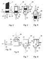
- Figs. 3 through 8 illustrate a first example of a process and apparatus according to the invention. It is observed that drainage columns are known in various embodiments. The invention is not limited to the use with one specific type of drainage column or drainage apparatus.
- Fig. 3 shows a curd block 9 cut from a curd column 30, received within a transfer vessel 31 with a bottom 32 that can be moved up and down by means of a cylinder 5, in a similar manner as described above for the known technique.
- the transfer vessel 31 unlike the above-described case or sliding cartridge, has a bottom 32, which, true, can be moved up and down like the supporting member 6, but which in the lowest position remains coupled to the transfer vessel, in the sense that the bottom, together with the rest of the vessel and the curd block contained therein, can be moved from the piston 33 of the cylinder 5 and sidewards over a supporting surface 34, as indicated by an arrow 35 in Fig. 3.
- the bottom side of the curd block now does not itself slide over a supporting surface and is therefore not damaged.
- the transfer vessel may have perforated or unperforated walls and/or a perforated or unperforated bottom.
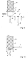
- the walls may further be smooth at the inner side or be provided with grooves. If desired, the walls may be provided at the lower side with means for preventing the bottom from falling out of the vessel. To this end, the walls could be provided e.g . with a narrow inwardly directed flange, as indicated by 40 in Fig. 9, on which the bottom 32 rests.
- the bottom may be provided with a circumferential shoulder 41 so as to form a smooth bottom side of the transfer vessel. However, the bottom may also be loose in the transfer vessel without being connected to the transfer vessel. It is important that the curd block is moved while lying on the bottom.
- the transfer vessel filled with a curd block is slid according to the invention into a reversing device 36.
- the reversing device 36 comprises a cylinder 37, which can act on the bottom 32 of the vessel, when the vessel is in a transfer position on a platform 38 of the reversing device, as shown in the right-hand part of Fig. 3. In the transfer position the transfer vessel 31 is above the cylinder 37 and below a reversed cheese vessel 39.
- the bottom 32 of the vessel 31 is now moved up by the cylinder 37 until the curd block 9 is completely or largely in the reversed cheese vessel 39, as shown in Fig. 4.
- the complete reversing device 36 is now rotated about a horizontal axis through 180°, as diagrammatically indicated by 43 with a curved arrow 44.
- the reversed position of the reversing device 36 is shown in Fig. 5.
- the curd block already begins to slide into the cheese vessel 39 after a rotation through 90° or more.
- the curd block completely sinks into the cheese vessel which is now in the normal position and can be discharged as indicated by an arrow 45 in Fig. 5.
- the piston may be connectable to the bottom by vacuum or mechanically.
- the piston may be provided e.g . with a suction cup that can be energized by reduced pressure or e.g . with parts of a bayonet catch, which cooperate with counterparts at the bottom.
- the bottom e.g . with lateral projections or the like, which prevent the bottom from falling out of the cheese vessel.
- the reversing device can be rotated into the starting position again.
- the bottom is then also moved again to the lower side of the transfer vessel by the cylinder 37. This may take place during and/or preceding and/or following the rotating-back movement.
- the bottom is withdrawn first (Fig. 6).
- Fig. 7 shows the reversing device 36 in the rotated-back position, in which the transfer vessel is in the usual position again. From the position shown in Fig. 7 the transfer vessel can be slid back by known per se means, not shown, to under the drainage column, whether or not via a bypass and/or a cleaning station. Subsequently, the reversing device 36 is provided again with a reversed cheese vessel 39 (Fig. 8), and the cycle can be repeated.
- the transfer vessel 31 must be temporarily coupled to the reversing device in order not to fall out of the reversing device in the reversed position.
- the cheese vessel 39 must be temporarily coupled to the reversing device.
- the reversing device may be provided with mechanical clamping means or with clamping means operating by vacuum. Also, use could be made of e.g . flanges at the transfer vessel and/or the reversing vessel, which engage the platform 38 or the carrier 47 for the cheese vessels under strips or the like.
- the reversing device may be arranged to transfer the contents of more than one transfer vessel simultaneously to a corresponding number of cheese vessels.
- Figs. 9 through 12 diagrammatically show a second example of a process and apparatus according to the invention.
- Fig. 9 diagrammatically shows the lowermost end of a drainage column 2 of a curd drainage apparatus.
- the drainage column contains a curd column 50.
- the curd column 50 rests on a guillotine blade 3, which closes the drainage column 2 and can be moved forward and backward in the manner indicated by an arrow 51 to close or release the drainage column and to cut off the lowermost part of a curd column 50 sunk from the drainage column, in a similar manner as described above.
- Fig. 9 the situation is such that the guillotine blade is in the closed position and that an empty transfer vessel 52 is present under the guillotine blade.
- the movable bottom 53 is moved up in the usual manner by means of a cylinder 5.
- the guillotine blade can be withdrawn, as soon as the drainage process of the curd column 50 has meanwhile made sufficient progress.
- the curd column 50 is supported by the bottom 53, which then sinks in the known manner (Fig. 10) until a cheese block of the desired height can be cut off.
- the guillotine blade is then brought into the closed position again, in which a cheese block 55 is cut off and the bottom 53 sinks further until it is at the height of the lower edge of the transfer vessel, as shown in Fig. 11.
- the transfer vessel 52 may then be moved sidewards to above a cheese vessel 54.
- the bottom 53 is supported by the piston 57, which then sinks, as indicated by an arrow 58, until the bottom 53 and the cheese block 55 are in the cheese vessel 54 and the situation shown in Fig. 12 has been realized.
- the filled cheese vessel is discharged by means of suitable discharge means (not shown) and an empty cheese vessel 54 conveyed into the position of the filled cheese vessel shown in Fig. 12.
- the movable bottom 53 is moved up by means of the cylinder 56 until a level corresponding to the lower side of the transfer vessel which is still (or again) in the place shown in Fig.
- the cheese vessels have a bottom that can be moved up and down, while the transfer vessel has no bottom of its own.
- the bottoms of the cheese vessels that can be moved up and down each time function as a temporary bottom for the transfer vessel.
- the temporary bottom can move sidewards with the transfer vessel.
- the movable bottom 53 is indicated by broken lines in the position in which the movable bottom cooperates with the transfer vessel. In the position indicated by full lines, the bottom 53 forms the bottom of the cheese vessel 54.
- diagrammatically shown at 56 is a cylinder with piston 57 for moving the bottom up and down.
- the bottom 52 must be able to pass the lower edge of the transfer vessel without hindrance.
- the cheese vessels 54 may be arranged in a manner such that the bottom 53 can be supported at the level of the lower edge of the cheese vessel.
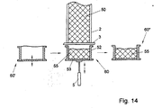
- Fig. 14 shows a drainage column 2 with a curd column 50 therein.
- a case 52 with a bottom 53 that can be moved up and down.
- the case 52 is not a part of a transfer vessel, but the case forms the side wall of a cheese vessel 60 which has a movable bottom 53.
- an empty cheese vessel 60' Positioned to the left of the cheese vessel 60 is an empty cheese vessel 60', which can take the place of the cheese vessel 60, as soon as the cheese vessel 60 has been moved from under the drainage column, e.g. into the position indicated at 60".
- a difference between a transfer vessel and a cheese vessel is that the cheese in a cheese vessel is subjected to a subsequent treatment, e.g . is pressed, that from a structural viewpoint a cheese vessel therefore must comply with more stringent requirements than a transfer vessel.
- the cheese vessels can be supplied with a supply conveyor and discharged with a discharge conveyor.
- push cylinders may be provided, similar to e.g . the cylinder 10 of Fig. 9, to place the cheese vessels under the drainage column and/or move them from under the drainage column.
- an intermittently driven continuous conveyor provided that the conveyor offers possibilities, e.g . openings in the conveyor surface, to allow the cylinder 5 to cooperate with the movable bottoms of the cheese vessels.
Landscapes
- Life Sciences & Earth Sciences (AREA)
- Animal Husbandry (AREA)
- Environmental Sciences (AREA)
- Beans For Foods Or Fodder (AREA)
- Dairy Products (AREA)
- Noodles (AREA)
Abstract
Description
- The invention relates to a process for transferring a curd block obtained from a drainage column to a cheese vessel, which comprises periodically lowering a curd column present in the drainage column into a case by means of a metering cylinder provided with a supporting member, cutting off a curd block at the bottom side of the curd column, and moving the case with the curd block therein sidewards.
- The invention further relates to an apparatus for using the process.
- In the known process and apparatus a bottomless case is used. The supporting member with the cut-off curd block thereon is lowered to just below the lower edge of the case. Then the case with the curd block just formed therein is moved sidewards over the supporting member to above a gate plate. The gate plate opens when a cheese vessel is present below the gate plate. The curd block falls into the cheese vessel and can then be conveyed on for further operations, such as a pressing operation.
- It is a drawback of this known technique that the displacement of the curd block over the supporting member and over the gate plate as well as over the junctions between the supporting member and the gate plate and the movement of the gate plate may cause damage to the bottom side of the curd block. This damage remains visible in the finally obtained cheese and is experienced as an annoying defect.
- This problem increases according as the weight of the curd blocks is greater. There is a tendency to cut off heavier blocks being 40 kg and more in weight. With such heavy blocks not only the above problems occur but also the problem that the height of fall of the block from the gate plate to the bottom of the cheese vessel may also cause damage and/or deformation of the curd block and therefore of the final cheese.
- It is an object of the invention to remove the above drawbacks and, in general, to provide an efficient and safe method of transferring a curd block from the bottom side of a curd column to a cheese vessel. To this end, a process of the above type is characterized according to the invention in that the case is a transfer vessel with a bottom that can be moved up and down; that the transfer vessel, after being filled with a curd block, is moved sidewards into a transfer position in a station.
- An apparatus for transferring a curd block obtained from a drainage column to a cheese vessel, which comprises periodically lowering a curd column present in a drainage column into a case by means of a supporting member; cutting off a curd block at the bottom side of the curd column, and moving the case with the curd block therein sidewards, is characterized according to the invention in that the case is a transfer vessel with a bottom that can be moved up and down by means of a metering cylinder; that means are provided for moving a filled transfer vessel sidewards into a transfer position in a station.
- The invention will hereinafter be explained in more detail with reference to the accompanying drawings, in which:
- Fig. 1 diagrammatically shows an example of a known curd drainage apparatus;
- Fig. 2 diagrammatically illustrates the steps of the known apparatus in steps A through H;
- Figs. 3 through 8 diagrammatically show an example of a process and apparatus according to the invention;
- Figs. 9 through 12 diagrammatically show another example of the invention;
- Fig. 13 diagrammatically shows a detail of an example of embodiment of a detail of a transfer vessel or a cheese vessel for use according to the invention; and
- Fig. 14 diagrammatically illustrates yet another example of the invention.
-
- Fig. 1 diagrammatically shows an example of a known
curd drainage apparatus 1. The apparatus shown has adrainage column 2, into which, in operation, a whey-curd mixture is fed at the top side. Thus a curd column is formed in thedrainage column 2. The whey can flow off via a perforated wall or perforated wall portions. Provided at the bottom side of the curd column is aguillotine blade 3, which is operated by acylinder 4, and by means of which a curd block is cut from the curd column at regular times. - To this end, a supporting
platform 6 is moved up by means of acylinder 5 until the height of the blade 3 (Fig. 2A). When the blade is in the open position (Fig. 2B), the curd column, while supported by the supporting platform, can be lowered by means of a suitable control of thecylinder 5. The curd column then sinks into abottomless case 7, also referred to as sliding cartridge (Fig. 2C). - In the drawings (Fig. 1, Fig. 2C) the supporting platform is still at a small distance above the lowest position indicated by 8. As soon as the supporting platform with the curd column thereon has reached a position corresponding to the desired height of the
curd block 9 to be formed, the lowermost part of the curd column is cut off by means of the blade 3 (Fig. 2D). Subsequently, the supporting platform with the curd block thereon is brought into the lowest position (Fig. 2E). When the supporting platform is in the lowest position, thesliding cartridge 7 is moved sidewards by means of a cylinder 10 (in the Figures to the right) (Fig. 2F). Thecurd block 9 thus slides over the piston onto agate plate 11. When a cheese vessel is present under the gate plate, as diagrammatically indicated by 12 in Fig. 2F, the gate plate opens and the curd block falls into the cheese vessel. Thesliding cartridge 7 is then withdrawn by thecylinder 10, while the filledcheese vessel 12 is discharged (Fig. 2G). Subsequently, the supporting platform moves up again (Fig. 2H), and the cycle can be repeated. - Figs. 3 through 8 illustrate a first example of a process and apparatus according to the invention. It is observed that drainage columns are known in various embodiments. The invention is not limited to the use with one specific type of drainage column or drainage apparatus.
- In Figs. 3 through 8, the same reference numerals are used for corresponding parts as in Figs. 1 and 2.
- Fig. 3 shows a
curd block 9 cut from acurd column 30, received within atransfer vessel 31 with abottom 32 that can be moved up and down by means of acylinder 5, in a similar manner as described above for the known technique. However, an important difference is that thetransfer vessel 31, unlike the above-described case or sliding cartridge, has abottom 32, which, true, can be moved up and down like the supportingmember 6, but which in the lowest position remains coupled to the transfer vessel, in the sense that the bottom, together with the rest of the vessel and the curd block contained therein, can be moved from thepiston 33 of thecylinder 5 and sidewards over a supportingsurface 34, as indicated by an arrow 35 in Fig. 3. The bottom side of the curd block now does not itself slide over a supporting surface and is therefore not damaged. - The transfer vessel may have perforated or unperforated walls and/or a perforated or unperforated bottom. The walls may further be smooth at the inner side or be provided with grooves. If desired, the walls may be provided at the lower side with means for preventing the bottom from falling out of the vessel. To this end, the walls could be provided e.g. with a narrow inwardly directed flange, as indicated by 40 in Fig. 9, on which the
bottom 32 rests. If required, the bottom may be provided with acircumferential shoulder 41 so as to form a smooth bottom side of the transfer vessel. However, the bottom may also be loose in the transfer vessel without being connected to the transfer vessel. It is important that the curd block is moved while lying on the bottom. - The transfer vessel filled with a curd block is slid according to the invention into a reversing
device 36. Thereversing device 36 comprises acylinder 37, which can act on thebottom 32 of the vessel, when the vessel is in a transfer position on aplatform 38 of the reversing device, as shown in the right-hand part of Fig. 3. In the transfer position thetransfer vessel 31 is above thecylinder 37 and below a reversedcheese vessel 39. - The bottom 32 of the
vessel 31 is now moved up by thecylinder 37 until thecurd block 9 is completely or largely in the reversedcheese vessel 39, as shown in Fig. 4. The complete reversingdevice 36 is now rotated about a horizontal axis through 180°, as diagrammatically indicated by 43 with acurved arrow 44. The reversed position of the reversingdevice 36 is shown in Fig. 5. During the rotation the curd block already begins to slide into thecheese vessel 39 after a rotation through 90° or more. In the reversed position the curd block completely sinks into the cheese vessel which is now in the normal position and can be discharged as indicated by anarrow 45 in Fig. 5. - To prevent the bottom 32 of the
transfer vessel 31 from falling on the curd block in the cheese vessel, a temporary coupling between thepiston 46 of thecylinder 37 and the bottom 32 can be applied. The piston may be connectable to the bottom by vacuum or mechanically. To this end, the piston may be provided e.g. with a suction cup that can be energized by reduced pressure or e.g. with parts of a bayonet catch, which cooperate with counterparts at the bottom. - By way of alternative, it is possible to provide the bottom e.g. with lateral projections or the like, which prevent the bottom from falling out of the cheese vessel.
- After the curd block has been taken over by the cheese vessel and the cheese vessel has been discharged, the reversing device can be rotated into the starting position again. The bottom is then also moved again to the lower side of the transfer vessel by the
cylinder 37. This may take place during and/or preceding and/or following the rotating-back movement. According to the process shown, the bottom is withdrawn first (Fig. 6). Fig. 7 shows the reversingdevice 36 in the rotated-back position, in which the transfer vessel is in the usual position again. From the position shown in Fig. 7 the transfer vessel can be slid back by known per se means, not shown, to under the drainage column, whether or not via a bypass and/or a cleaning station. Subsequently, the reversingdevice 36 is provided again with a reversed cheese vessel 39 (Fig. 8), and the cycle can be repeated. - The
transfer vessel 31 must be temporarily coupled to the reversing device in order not to fall out of the reversing device in the reversed position. Similarly, thecheese vessel 39 must be temporarily coupled to the reversing device. To this end, the reversing device may be provided with mechanical clamping means or with clamping means operating by vacuum. Also, use could be made of e.g. flanges at the transfer vessel and/or the reversing vessel, which engage theplatform 38 or thecarrier 47 for the cheese vessels under strips or the like. - It is observed that, if desired, the reversing device may be arranged to transfer the contents of more than one transfer vessel simultaneously to a corresponding number of cheese vessels.
- Figs. 9 through 12 diagrammatically show a second example of a process and apparatus according to the invention. Fig. 9 diagrammatically shows the lowermost end of a
drainage column 2 of a curd drainage apparatus. The drainage column contains acurd column 50. Thecurd column 50 rests on aguillotine blade 3, which closes thedrainage column 2 and can be moved forward and backward in the manner indicated by anarrow 51 to close or release the drainage column and to cut off the lowermost part of acurd column 50 sunk from the drainage column, in a similar manner as described above. - In Fig. 9 the situation is such that the guillotine blade is in the closed position and that an
empty transfer vessel 52 is present under the guillotine blade. - When a transfer vessel is present under the drainage column, the movable bottom 53 is moved up in the usual manner by means of a
cylinder 5. When the bottom is exactly under the guillotine blade, the guillotine blade can be withdrawn, as soon as the drainage process of thecurd column 50 has meanwhile made sufficient progress. When the guillotine blade has been withdrawn, thecurd column 50 is supported by the bottom 53, which then sinks in the known manner (Fig. 10) until a cheese block of the desired height can be cut off. The guillotine blade is then brought into the closed position again, in which acheese block 55 is cut off and the bottom 53 sinks further until it is at the height of the lower edge of the transfer vessel, as shown in Fig. 11. Thetransfer vessel 52 may then be moved sidewards to above acheese vessel 54. In this position, indicated in Fig. 11 by broken lines, the bottom 53 is supported by thepiston 57, which then sinks, as indicated by anarrow 58, until the bottom 53 and thecheese block 55 are in thecheese vessel 54 and the situation shown in Fig. 12 has been realized. After thecheese vessel 54 has been filled with acheese block 55, the filled cheese vessel is discharged by means of suitable discharge means (not shown) and anempty cheese vessel 54 conveyed into the position of the filled cheese vessel shown in Fig. 12. Subsequently, the movable bottom 53 is moved up by means of thecylinder 56 until a level corresponding to the lower side of the transfer vessel which is still (or again) in the place shown in Fig. 12, as indicated in Fig. 12 by broken lines. Thetransfer vessel 52 is then moved again, together with the bottom 53, to under thedrainage column 2, as shown in Fig. 9. Thepiston 57 then preferably remains in the high position, as likewise shown in Fig. 9. Unlike in the example of embodiment described before, the cheese vessels have a bottom that can be moved up and down, while the transfer vessel has no bottom of its own. The bottoms of the cheese vessels that can be moved up and down each time function as a temporary bottom for the transfer vessel. The temporary bottom can move sidewards with the transfer vessel. In Fig. 12 the movable bottom 53 is indicated by broken lines in the position in which the movable bottom cooperates with the transfer vessel. In the position indicated by full lines, the bottom 53 forms the bottom of thecheese vessel 54. Furthermore, diagrammatically shown at 56 is a cylinder withpiston 57 for moving the bottom up and down. The bottom 52 must be able to pass the lower edge of the transfer vessel without hindrance. However, in a similar manner as shown in Fig. 13, thecheese vessels 54 may be arranged in a manner such that the bottom 53 can be supported at the level of the lower edge of the cheese vessel. - According to yet another elaboration on the inventive concept, by using cheese vessels with a bottom that can be moved up and down, as described above, the cut-off curd blocks can be collected in the cheese vessels directly under the drainage column. A separate transfer vessel is not required, then. For completeness' sake, such a process is diagrammatically shown once more in Fig. 14.
- Fig. 14 shows a
drainage column 2 with acurd column 50 therein. Provided under the drainage column is acase 52 with a bottom 53 that can be moved up and down. In this example, however, thecase 52 is not a part of a transfer vessel, but the case forms the side wall of acheese vessel 60 which has amovable bottom 53. Positioned to the left of thecheese vessel 60 is an empty cheese vessel 60', which can take the place of thecheese vessel 60, as soon as thecheese vessel 60 has been moved from under the drainage column, e.g. into the position indicated at 60". A difference between a transfer vessel and a cheese vessel is that the cheese in a cheese vessel is subjected to a subsequent treatment, e.g. is pressed, that from a structural viewpoint a cheese vessel therefore must comply with more stringent requirements than a transfer vessel. - The cheese vessels can be supplied with a supply conveyor and discharged with a discharge conveyor. In this connection, push cylinders may be provided, similar to e.g. the
cylinder 10 of Fig. 9, to place the cheese vessels under the drainage column and/or move them from under the drainage column. It is also possible to use an intermittently driven continuous conveyor, provided that the conveyor offers possibilities, e.g. openings in the conveyor surface, to allow thecylinder 5 to cooperate with the movable bottoms of the cheese vessels. - It is observed that after the foregoing various modifications are obvious to those skilled in the art. Thus, for instance, the process described may be used both for columns with a single curd column and for columns with several curd columns within one case. In the latter case, either one curd block or more than one curd block can be cut off simultaneously in a single cutting operation. Also for moving and retaining the transfer vessel and the cheese vessels different solutions are conceivable. These and similar modifications are deemed to fall within the scope of the invention.
Claims (27)
- A process for transferring a curd block obtained from a drainage column to a cheese vessel, which comprises periodically lowering a curd column present in the drainage column into a case by means of a supporting member, cutting off a curd block at the bottom side of the curd column, and moving the case with the curd block therein sidewards,
characterized by using a supporting member which comprises a bottom that can be moved up and down, which cooperates with the case in such a manner that the case, after being filled with a curd block, can be moved sidewards, while the curd block remains on the movable bottom during movement. - A process according to claim 1, characterized in that the case is a transfer vessel with a bottom that can be moved up and down, and that the transfer vessel, after being filled with a curd block, is moved sidewards into a transfer position in a transfer station, said curd block remaining on the movable bottom during movement.
- A process according to claim 2, characterized in that the transfer station is a reversing station, and that in the reversing station above the transfer position of the transfer vessel a cheese vessel is placed in the reversed position, that the bottom of the transfer vessel is moved up until the curd block at least partly extends into the cheese vessel, that, subsequently, the reversing station is rotated about a horizontal axis until the cheese vessel is in the normal position, following which the cheese vessel is discharged, and that the reversing station and the bottom of the transfer vessel is returned again to the starting position, and that, finally, the transfer vessel is removed from the reversing station.
- A process according to claim 2 or 3, characterized in that the transfer vessel is returned to a drainage column via a bypass of the reversing station.
- A process according to claim 2, characterized in that in the transfer station the curd block lying on the movable bottom is transferred to a ready cheese vessel, and that the cheese vessel with the curd block lying therein on the movable bottom is then discharged from the transfer station and the transfer vessel is returned to the drainage column.
- A process according to claim 5, characterized in that the movable bottom for transferring a curd block from a transfer vessel to a cheese vessel is moved down from the transfer vessel into a bottomless cheese vessel present under the transfer vessel.
- A process according to claim 1, characterized in that the case used is a cheese vessel with a movable bottom which is filled with a curd block directly under the drainage column, said cheese vessel forming part of a number of similar cheese vessels which are successively supplied to a drainage column, and which, after being filled with a curd block, are each conveyed by means of suitable conveying means to at least one transfer station for further processing of the curd block, said curd block always remaining supported by the movable bottom of a cheese vessel.
- An apparatus for transferring a curd block obtained from a drainage column to a cheese vessel, which comprises periodically lowering a curd column present in the drainage column into a case by means of a supporting member, cutting off a curd block at the bottom side of the curd column, and moving the case with the curd block therein sidewards, characterized in that the supporting member comprises a bottom that can be moved up and down by means of a metering cylinder, and that means are provided for moving sidewards a filled case together with the movable bottom and a curd block lying thereon.
- An apparatus according to claim 8, characterized in that the case is a transfer vessel with a bottom that can be moved up and down, and that said means for moving the case sidewards are arranged to move the case together with the_ movable bottom and a curd block lying thereon sidewards into a transfer position in a transfer station which comprises at least one transfer position.
- An apparatus according to claim 9, characterized in that the transfer station is a reversing station which comprises means for placing a cheese vessel in the reversed position above the transfer position, that the reversing station further comprises means for moving up the bottom of the transfer vessel with a curd block thereon until the curd block at least partly extends into the cheese vessel, and that rotation means are provided to bring the reversing station into the reversed position with the cheese vessel below and the transfer vessel above so that the curd block can slide into the cheese vessel.
- An apparatus according to claim 10, characterized in that the means for moving up the bottom of the transfer vessel comprise a cylinder mounted in the reversing station with a piston acting on the bottom of the transfer vessel.
- An apparatus according to claim 11, characterized in that the piston comprises coupling means for effecting a temporary coupling with the bottom of the transfer vessel.
- An apparatus according to claim 12, characterized in that the coupling means operate by vacuum.
- An apparatus according to claim 12, characterized in that the coupling means effect a temporary mechanical coupling.
- An apparatus according to claim 14, characterized in that the coupling means effect a bayonet catch.
- An apparatus according to any of claims 10 through 15, characterized in that the reversing station is arranged for rotation about a horizontal axis.
- An apparatus according to any of claims 10 through 16, characterized in that the reversing station comprises retaining means for a cheese vessel and for a transfer vessel.
- An apparatus according to claim 17, characterized in that the retaining means comprise clamping means.
- An apparatus according to claim 17 or 18, characterized in that the retaining means comprise rail-like members that can engage around flanges of a cheese vessel and/or transfer vessel.
- An apparatus according to claim 9, characterized by transfer means arranged to remove the movable bottom with the curd block lying thereon from a transfer vessel and place it in a cheese vessel.
- An apparatus according to claim 20, characterized in that the transfer means comprise a cylinder provided with a piston, said cylinder being arranged to support the movable bottom and move it down from the transfer vessel into a cheese vessel placed under the transfer vessel.
- An apparatus according to claim 21, characterized in that the movable bottom, after being transferred to a cheese vessel, forms the bottom of the cheese vessel.
- An apparatus for forming curd blocks and discharging them in cheese vessels, comprising a drainage apparatus with one or more drainage columns, which each comprise one or more drainage tubes, characterized by an apparatus for transferring curd blocks as described in one of claims 8 through 22.
- An apparatus according to claim 23, characterized by a bypass for returning emptied transfer vessels.
- An apparatus according to claim 24, characterized in that the bypass leads along a cleaning station.
- An apparatus according to claim 8, characterized in that the case is a cheese vessel with a movable bottom, said cheese vessel forming part of a number of similar cheese vessels which are successively supplied to a drainage column by means of suitable supply means, each to be filled with a curd block directly under the drainage column, and which, after being filled, are each conveyed by means of suitable discharge means to at least one processing station for further processing of the curd block, while the curd block lies in the cheese vessel on the movable bottom of the cheese vessel.
- An apparatus according to claim 26, characterized in that the supply means and the discharge means are formed by a continuous conveyor.
Applications Claiming Priority (2)
| Application Number | Priority Date | Filing Date | Title |
|---|---|---|---|
| NL1008151A NL1008151C2 (en) | 1998-01-28 | 1998-01-28 | Method and device for transferring a block of curd obtained from a drainage column to a cheese vat. |
| NL1008151 | 1998-01-28 |
Publications (2)
| Publication Number | Publication Date |
|---|---|
| EP0931453A1 EP0931453A1 (en) | 1999-07-28 |
| EP0931453B1 true EP0931453B1 (en) | 2002-05-15 |
Family
ID=19766431
Family Applications (1)
| Application Number | Title | Priority Date | Filing Date |
|---|---|---|---|
| EP99200238A Expired - Lifetime EP0931453B1 (en) | 1998-01-28 | 1999-01-27 | Process and apparatus for transferring a curd block obtained from a drainage column to a cheese vessel |
Country Status (9)
| Country | Link |
|---|---|
| EP (1) | EP0931453B1 (en) |
| AT (1) | ATE217479T1 (en) |
| AU (1) | AU740376B2 (en) |
| DE (1) | DE69901464T2 (en) |
| DK (1) | DK0931453T3 (en) |
| ES (1) | ES2177195T3 (en) |
| NL (1) | NL1008151C2 (en) |
| NO (1) | NO314531B1 (en) |
| NZ (1) | NZ333933A (en) |
Families Citing this family (1)
| Publication number | Priority date | Publication date | Assignee | Title |
|---|---|---|---|---|
| NL2002041C (en) * | 2008-09-30 | 2010-03-31 | Tetra Laval Holdings & Finance | CHEESE PREPARATION DEVICE WITH VERTICAL DRAINING COLUMN AND DOSING DEVICE. |
Family Cites Families (3)
| Publication number | Priority date | Publication date | Assignee | Title |
|---|---|---|---|---|
| GB2125674B (en) * | 1982-08-24 | 1985-11-27 | Alfa Laval Cheddar Systems Ltd | Cheese block former |
| NL8600551A (en) * | 1986-03-04 | 1987-10-01 | Stork Friesland Bv | METHOD AND APPARATUS FOR TRANSPORTING WRENCH PORTIONS FROM A WRONG DOSING COLUMN TO A CHEESE FORM ON A DRAIN IN CHEESE PREPARATION |
| GB8807761D0 (en) * | 1988-03-31 | 1988-05-05 | Alfa Laval Cheese Systems | Method & apparatus for producing moulded cheese blocks |
-
1998
- 1998-01-28 NL NL1008151A patent/NL1008151C2/en not_active IP Right Cessation
-
1999
- 1999-01-27 NZ NZ333933A patent/NZ333933A/en not_active IP Right Cessation
- 1999-01-27 DE DE69901464T patent/DE69901464T2/en not_active Expired - Lifetime
- 1999-01-27 EP EP99200238A patent/EP0931453B1/en not_active Expired - Lifetime
- 1999-01-27 AU AU13218/99A patent/AU740376B2/en not_active Ceased
- 1999-01-27 AT AT99200238T patent/ATE217479T1/en not_active IP Right Cessation
- 1999-01-27 DK DK99200238T patent/DK0931453T3/en active
- 1999-01-27 ES ES99200238T patent/ES2177195T3/en not_active Expired - Lifetime
- 1999-01-27 NO NO19990376A patent/NO314531B1/en not_active IP Right Cessation
Also Published As
| Publication number | Publication date |
|---|---|
| ES2177195T3 (en) | 2002-12-01 |
| NO990376D0 (en) | 1999-01-27 |
| ATE217479T1 (en) | 2002-06-15 |
| AU1321899A (en) | 1999-08-19 |
| DK0931453T3 (en) | 2002-08-19 |
| NO990376L (en) | 1999-07-29 |
| AU740376B2 (en) | 2001-11-01 |
| NZ333933A (en) | 2000-03-27 |
| DE69901464T2 (en) | 2003-01-16 |
| NL1008151C2 (en) | 1999-07-29 |
| EP0931453A1 (en) | 1999-07-28 |
| NO314531B1 (en) | 2003-04-07 |
| DE69901464D1 (en) | 2002-06-20 |
Similar Documents
| Publication | Publication Date | Title |
|---|---|---|
| US5553988A (en) | Method of and apparatus for manipulating containers for cigarette trays | |
| EP0259342B1 (en) | A device for pressing and molding curd | |
| US20020152859A1 (en) | Method and apparatus to remove pieces cut from a bar-shaped workpiece with a cutting machine | |
| DK162016B (en) | Apparatus for dispensing portions of a heated foodstuff | |
| US6219996B1 (en) | Systems for filling non-round containers, especially frozen dessert containers | |
| US5146845A (en) | Continuous cheese former for bulk cheese | |
| US5634344A (en) | Method for producing ice vessel and apparatus therefor | |
| EP0596183B1 (en) | An underwater bin-filling plant | |
| EP0931453B1 (en) | Process and apparatus for transferring a curd block obtained from a drainage column to a cheese vessel | |
| EP0367353B1 (en) | Method for the cyclic preparation of a length of curds and installation for carrying out this method | |
| US3643822A (en) | Can palletizer | |
| EP0088258A1 (en) | Production line for bitumen cakes | |
| EP0916256B1 (en) | Method and apparatus for producing cut fresh curd blocks | |
| EP0235867A1 (en) | Method and apparatus for conveying portions of curd from a curd dispensing column to a cheese mould on a discharge track during cheese-making | |
| US3823826A (en) | Horizontal filter press | |
| CA2254177C (en) | Method and apparatus for producing cut fresh curd blocks | |
| EP0916257B1 (en) | Method and apparatus for producing packed fresh curd blocks | |
| EP0395288A1 (en) | Method and apparatus for unloading boxes or the like | |
| EP0592612B1 (en) | Apparatus and method for making bulk cheese | |
| GB2120198A (en) | Pallet loading apparatus | |
| PL221167B1 (en) | Production line for manufacturing cottage cheese, especially of the sliced type | |
| US3159896A (en) | Machine for handling clay pipe | |
| EP2348820B1 (en) | Cheese making apparatus with vertical draining column and dosing device | |
| JPH04158756A (en) | Device and method for cutting and carrying bean curd | |
| JPS6124102B2 (en) |
Legal Events
| Date | Code | Title | Description |
|---|---|---|---|
| PUAI | Public reference made under article 153(3) epc to a published international application that has entered the european phase |
Free format text: ORIGINAL CODE: 0009012 |
|
| AK | Designated contracting states |
Kind code of ref document: A1 Designated state(s): AT BE CH DE DK ES FR GB IT LI NL SE |
|
| AX | Request for extension of the european patent |
Free format text: AL;LT;LV;MK;RO;SI |
|
| 17P | Request for examination filed |
Effective date: 19991014 |
|
| AKX | Designation fees paid |
Free format text: AT BE CH DE DK ES FR GB IT LI NL SE |
|
| GRAG | Despatch of communication of intention to grant |
Free format text: ORIGINAL CODE: EPIDOS AGRA |
|
| 17Q | First examination report despatched |
Effective date: 20011129 |
|
| GRAG | Despatch of communication of intention to grant |
Free format text: ORIGINAL CODE: EPIDOS AGRA |
|
| GRAH | Despatch of communication of intention to grant a patent |
Free format text: ORIGINAL CODE: EPIDOS IGRA |
|
| GRAH | Despatch of communication of intention to grant a patent |
Free format text: ORIGINAL CODE: EPIDOS IGRA |
|
| GRAA | (expected) grant |
Free format text: ORIGINAL CODE: 0009210 |
|
| AK | Designated contracting states |
Kind code of ref document: B1 Designated state(s): AT BE CH DE DK ES FR GB IT LI NL SE |
|
| REF | Corresponds to: |
Ref document number: 217479 Country of ref document: AT Date of ref document: 20020615 Kind code of ref document: T |
|
| REG | Reference to a national code |
Ref country code: GB Ref legal event code: FG4D Ref country code: CH Ref legal event code: EP |
|
| REF | Corresponds to: |
Ref document number: 69901464 Country of ref document: DE Date of ref document: 20020620 |
|
| REG | Reference to a national code |
Ref country code: DK Ref legal event code: T3 |
|
| REG | Reference to a national code |
Ref country code: CH Ref legal event code: NV Representative=s name: MICHELI & CIE INGENIEURS-CONSEILS |
|
| ET | Fr: translation filed | ||
| REG | Reference to a national code |
Ref country code: ES Ref legal event code: FG2A Ref document number: 2177195 Country of ref document: ES Kind code of ref document: T3 |
|
| PGFP | Annual fee paid to national office [announced via postgrant information from national office to epo] |
Ref country code: GB Payment date: 20030122 Year of fee payment: 5 |
|
| PGFP | Annual fee paid to national office [announced via postgrant information from national office to epo] |
Ref country code: AT Payment date: 20030123 Year of fee payment: 5 |
|
| PGFP | Annual fee paid to national office [announced via postgrant information from national office to epo] |
Ref country code: FR Payment date: 20030127 Year of fee payment: 5 |
|
| PGFP | Annual fee paid to national office [announced via postgrant information from national office to epo] |
Ref country code: BE Payment date: 20030214 Year of fee payment: 5 |
|
| PGFP | Annual fee paid to national office [announced via postgrant information from national office to epo] |
Ref country code: ES Payment date: 20030224 Year of fee payment: 5 |
|
| PLBE | No opposition filed within time limit |
Free format text: ORIGINAL CODE: 0009261 |
|
| STAA | Information on the status of an ep patent application or granted ep patent |
Free format text: STATUS: NO OPPOSITION FILED WITHIN TIME LIMIT |
|
| PGFP | Annual fee paid to national office [announced via postgrant information from national office to epo] |
Ref country code: CH Payment date: 20030402 Year of fee payment: 5 |
|
| 26N | No opposition filed |
Effective date: 20030218 |
|
| PG25 | Lapsed in a contracting state [announced via postgrant information from national office to epo] |
Ref country code: GB Free format text: LAPSE BECAUSE OF NON-PAYMENT OF DUE FEES Effective date: 20040127 Ref country code: AT Free format text: LAPSE BECAUSE OF NON-PAYMENT OF DUE FEES Effective date: 20040127 |
|
| PG25 | Lapsed in a contracting state [announced via postgrant information from national office to epo] |
Ref country code: ES Free format text: LAPSE BECAUSE OF NON-PAYMENT OF DUE FEES Effective date: 20040128 |
|
| PG25 | Lapsed in a contracting state [announced via postgrant information from national office to epo] |
Ref country code: LI Free format text: LAPSE BECAUSE OF NON-PAYMENT OF DUE FEES Effective date: 20040131 Ref country code: CH Free format text: LAPSE BECAUSE OF NON-PAYMENT OF DUE FEES Effective date: 20040131 Ref country code: BE Free format text: LAPSE BECAUSE OF NON-PAYMENT OF DUE FEES Effective date: 20040131 |
|
| BERE | Be: lapsed |
Owner name: S.A. *TETRA LAVAL HOLDINGS & FINANCE Effective date: 20040131 |
|
| GBPC | Gb: european patent ceased through non-payment of renewal fee |
Effective date: 20040127 |
|
| REG | Reference to a national code |
Ref country code: CH Ref legal event code: PL |
|
| PG25 | Lapsed in a contracting state [announced via postgrant information from national office to epo] |
Ref country code: FR Free format text: LAPSE BECAUSE OF NON-PAYMENT OF DUE FEES Effective date: 20040930 |
|
| REG | Reference to a national code |
Ref country code: FR Ref legal event code: ST |
|
| PG25 | Lapsed in a contracting state [announced via postgrant information from national office to epo] |
Ref country code: IT Free format text: LAPSE BECAUSE OF NON-PAYMENT OF DUE FEES;WARNING: LAPSES OF ITALIAN PATENTS WITH EFFECTIVE DATE BEFORE 2007 MAY HAVE OCCURRED AT ANY TIME BEFORE 2007. THE CORRECT EFFECTIVE DATE MAY BE DIFFERENT FROM THE ONE RECORDED. Effective date: 20050127 |
|
| REG | Reference to a national code |
Ref country code: ES Ref legal event code: FD2A Effective date: 20040128 |
|
| PGFP | Annual fee paid to national office [announced via postgrant information from national office to epo] |
Ref country code: NL Payment date: 20180115 Year of fee payment: 20 |
|
| PGFP | Annual fee paid to national office [announced via postgrant information from national office to epo] |
Ref country code: DE Payment date: 20180117 Year of fee payment: 20 Ref country code: DK Payment date: 20180110 Year of fee payment: 20 |
|
| PGFP | Annual fee paid to national office [announced via postgrant information from national office to epo] |
Ref country code: SE Payment date: 20180213 Year of fee payment: 20 |
|
| REG | Reference to a national code |
Ref country code: DE Ref legal event code: R071 Ref document number: 69901464 Country of ref document: DE |
|
| REG | Reference to a national code |
Ref country code: DK Ref legal event code: EUP Effective date: 20190127 |
|
| REG | Reference to a national code |
Ref country code: NL Ref legal event code: MK Effective date: 20190126 |