EP0930703A2 - Surface acoustic wave filter having improved frequency characteristic - Google Patents
Surface acoustic wave filter having improved frequency characteristic Download PDFInfo
- Publication number
- EP0930703A2 EP0930703A2 EP99100368A EP99100368A EP0930703A2 EP 0930703 A2 EP0930703 A2 EP 0930703A2 EP 99100368 A EP99100368 A EP 99100368A EP 99100368 A EP99100368 A EP 99100368A EP 0930703 A2 EP0930703 A2 EP 0930703A2
- Authority
- EP
- European Patent Office
- Prior art keywords
- surface acoustic
- acoustic wave
- idts
- wave filter
- electrode
- Prior art date
- Legal status (The legal status is an assumption and is not a legal conclusion. Google has not performed a legal analysis and makes no representation as to the accuracy of the status listed.)
- Withdrawn
Links
- 238000010897 surface acoustic wave method Methods 0.000 title claims abstract description 79
- 239000000758 substrate Substances 0.000 claims abstract description 25
- 230000005540 biological transmission Effects 0.000 claims abstract description 9
- XAGFODPZIPBFFR-UHFFFAOYSA-N aluminium Chemical compound [Al] XAGFODPZIPBFFR-UHFFFAOYSA-N 0.000 claims abstract description 7
- 229910052782 aluminium Inorganic materials 0.000 claims abstract description 7
- 239000013078 crystal Substances 0.000 claims abstract description 7
- 239000000956 alloy Substances 0.000 claims description 3
- 229910045601 alloy Inorganic materials 0.000 claims description 3
- PSHMSSXLYVAENJ-UHFFFAOYSA-N dilithium;[oxido(oxoboranyloxy)boranyl]oxy-oxoboranyloxyborinate Chemical compound [Li+].[Li+].O=BOB([O-])OB([O-])OB=O PSHMSSXLYVAENJ-UHFFFAOYSA-N 0.000 claims description 3
- WSMQKESQZFQMFW-UHFFFAOYSA-N 5-methyl-pyrazole-3-carboxylic acid Chemical compound CC1=CC(C(O)=O)=NN1 WSMQKESQZFQMFW-UHFFFAOYSA-N 0.000 claims description 2
- GQYHUHYESMUTHG-UHFFFAOYSA-N lithium niobate Chemical compound [Li+].[O-][Nb](=O)=O GQYHUHYESMUTHG-UHFFFAOYSA-N 0.000 claims description 2
- 238000000151 deposition Methods 0.000 abstract description 3
- 239000010409 thin film Substances 0.000 abstract description 3
- 230000000644 propagated effect Effects 0.000 description 5
- 230000000694 effects Effects 0.000 description 3
- 230000001629 suppression Effects 0.000 description 3
- 238000010276 construction Methods 0.000 description 2
- 230000009466 transformation Effects 0.000 description 2
- 229910003327 LiNbO3 Inorganic materials 0.000 description 1
- 229910012463 LiTaO3 Inorganic materials 0.000 description 1
- 230000006866 deterioration Effects 0.000 description 1
- 238000005516 engineering process Methods 0.000 description 1
- 238000011835 investigation Methods 0.000 description 1
- 239000000463 material Substances 0.000 description 1
Images


Classifications
-
- H—ELECTRICITY
- H03—ELECTRONIC CIRCUITRY
- H03H—IMPEDANCE NETWORKS, e.g. RESONANT CIRCUITS; RESONATORS
- H03H9/00—Networks comprising electromechanical or electro-acoustic devices; Electromechanical resonators
- H03H9/46—Filters
- H03H9/64—Filters using surface acoustic waves
- H03H9/6423—Means for obtaining a particular transfer characteristic
- H03H9/6433—Coupled resonator filters
-
- H—ELECTRICITY
- H03—ELECTRONIC CIRCUITRY
- H03H—IMPEDANCE NETWORKS, e.g. RESONANT CIRCUITS; RESONATORS
- H03H9/00—Networks comprising electromechanical or electro-acoustic devices; Electromechanical resonators
- H03H9/25—Constructional features of resonators using surface acoustic waves
Definitions
- the present invention relates to a surface acoustic wave filter in which IDTs (Inter Digital Transducer) on an input side and on an output side each made of a plurality of electrode digits are formed on a piezoelectric substrate with a spacing interposed therebetween.
- IDTs Inter Digital Transducer
- Fig. 1 is a plan view showing an example of a conventional surface acoustic wave filter.
- This surface acoustic wave filter 102 has IDTs 106, 108 on an input side and on an output side, which are surface acoustic waves transducers, formed with a spacing interposed therebetween on piezoelectric substrate 104 made of crystal and the like.
- the width of each electrode digit of each of IDTs 106, 108 is ⁇ /4 where ⁇ is the wavelength of the surface acoustic wave during resonance.
- One electrode 114 of IDTs 106, 108 are connected to input terminal 116 and output terminal 118 the other electrodes 120 are both grounded.
- IDT 106 when an alternating signal is supplied from input terminal 116, IDT 106 causes a surface acoustic wave to be excited on piezoelectric substrate 104.
- the wave is propagated in a direction orthogonal to the extending direction of each electrode digit 112 constituting IDT 106, forms a standing wave while repeating multiple reflection between IDTS 106 and 108, and is received in IDT 108 and then outputted from output terminal 118 as an electric signal.
- Surface acoustic wave filter 102 having such construction as described above is also referred to as a vertical mode resonator type surface acoustic wave filter since the surface acoustic wave is propagated in the vertical direction and the resonance of the modes distributed in the same direction as the propagated direction is utilized.
- Fig. 2 is a graph showing the frequency characteristic of surface acoustic wave filter 102.
- the horizontal axis represents the frequency and the vertical axis represents the attenuation factor, respectively.
- An ideal characteristic for surface acoustic wave filter 102 which is a band-pass filter is to pass signals only in the pass-band near the center frequency f. However, signals are actually passed in some degree even at a point away from the center frequency, which phenomenon appears as a spurious signal in the frequency characteristic.
- a typical spurious signal 122 occurs in a region higher than the center frequency, which causes a reduction in the amount of attenuation out of the band and a deterioration in the frequency characteristic as a band-pass filter.
- N ⁇ 0.55 is satisfied where ⁇ is a reflection coefficient of an electrode digit and N is the total number of pairs of the electrode digits constituting IDTs on an input side and on an output side
- fH ⁇ -17.5W+210 is satisfied where W(wavelength) is the aperture width of the surface acoustic wave transmission path formed of the IDTs on the input side and on the output side, f(Hz) is the center frequency of the filter, and H(m) is the thickness of the electrode digits.
- the reflection coefficient ⁇ of the electrode digit and the total number N of the pairs of the electrode digits of the IDT are set to satisfy N ⁇ 0.55 and the aperture width W of the surface acoustic wave transmission path, the center frequency f of the filter, and the thickness H of the electrode digits are set to satisfy fH ⁇ -17.5W+210, bulk mode transformation in the IDT is increased. As a result, the spurious signal typical of the vertical mode resonator type surface acoustic wave filter is suppressed, thereby improving the frequency characteristic as a band-pass filter.
- surface acoustic wave filter 2 is a vertical mode resonator type surface acoustic wave filter serving as a band-pass filter and includes IDTs 4, 6 on an input side and on an output side.
- IDTs 4, 6 are formed by depositing a thin film made of aluminum or an alloy of aluminum on ST cut crystal substrate 8 (hereinafter also referred to as piezoelectric substrate 8) and disposed on piezoelectric substrate 8 with a spacing interposed therebetween.
- Each of IDTs 4, 6 is made of plurality of pairs of inter digital shape electrodes.
- the width of each electrode digit 12 is ⁇ /4 where ⁇ is the wavelength of the surface acoustic wave during resonance.
- One electrodes 14 of IDTs 4, 6 are connected to input terminal 16 and output terminal 18, respectively, and the other electrodes 20 are both grounded.
- a reflection coefficient per electrode digit i.e. acoustic impedance discontinuous coefficient
- N the total number of the pairs of the electrode digits constituting IDTs 4, 6 on the input side and on the output side
- the setting the product of the total number N of the pairs of the electrode digits and the reflection coefficient ⁇ to be 0.55 or more is equivalent to the setting the reflection coefficient of the overall surface waveguide path to be 1.5 or more.
- This value can be realized with the existing technology in a vertical mode resonator type surface acoustic wave filter having a usual constitution such as surface acoustic wave filter 2 of this embodiment.
- the aperture width W(wavelength) of the surface acoustic wave transmission path formed of IDTs 4, 6, the center frequency f of the filter, and the thickness H(m) of the electrode digits are set to satisfy the equation (2).
- the aperture width W(wavelength) indicates that the aperture width is W times the wavelength of the surface acoustic wave in a resonant state. fH ⁇ -17.5W+210
- the aperture width W of the surface acoustic wave transmission path is shorter than that of a conventional surface acoustic wave filter when the center frequency f and the thickness H of the electrode digits are those as conventional.
- surface acoustic wave filter 2 constituted as described above is the same as that of conventional surface acoustic wave filter 10. Specifically, when an alternating signal is supplied from input terminal 16, IDT 4 causes the surface acoustic wave to be excited on piezoelectric substrate 8. The wave is propagated in a direction orthogonal to the extending direction of each electrode digit 12 constituting IDT, forms a standing wave while repeating multiple reflection between IDTs 4 and 6, and is received in IDT 6 and then outputted from output terminal 18 as an electric signal.
- Fig. 4 is a graph showing the frequency characteristic of surface acoustic wave filter 2, in which the horizontal axis represents the frequency and the vertical axis represents the attenuation factor, respectively.
- spurious signal 22 typical of a vertical mode resonator type surface acoustic wave filter occurring on the higher side than the center frequency f is greatly reduced, improving the frequency characteristic as a pass-band filter.
- dotted line 24 represents the level of spurious signal 122 in the case of the conventional surface acoustic wave filter 102 (Fig. 2).
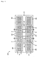
- FIG. 5 there is shown a surface acoustic wave filter according to a second embodiment of the present invention.
- elements identical to those in Fig. 3 are designated by the same reference numerals and symbols and will not be described in detail herein.
- a pair of grating reflectors 28, 30 are formed on piezoelectric substrate 8 to sandwich IDTs 4, 6 on an input side and on an output side therebetween. Furthermore, two sets each made of IDTs 4, 6 and a pair of grating reflectors 28, 30 are formed on piezoelectric substrate 8. These grating reflectors 28, 30 are formed by depositing a thin film made of aluminum or an alloy of aluminum on piezoelectric substrate 8 in this embodiment similarly to IDTS 4, 6.
- the aperture width of the surface acoustic wave transmission path formed of respective grating reflectors 28, 30 is substantially coincident with the aperture width W of the surface acoustic wave transmission path made of IDTs 4, 6.
- Electrodes 14 of the respective IDTs 4 are both connected to input terminal 16 and electrodes 14 of the respective IDTs 6 are both connected to output terminal 18.
- electrodes 20 of the respective IDTs 4 and electrodes 20 of the respective IDTs 6 are both grounded.
- the product N ⁇ of the total number N of the pairs of electrode digits 12 and a reflection coefficient ⁇ per electrode digit is set to be 3.9
- the product fH of the center frequency f and the thickness H of electrode digits 12 is set to be 70
- the aperture width W of the surface acoustic waveguide path is set to be 5.5(wavelength), respectively.
- each IDT 4 when an alternating signal is supplied from input terminal 16, each IDT 4 causes a surface acoustic wave to be excited on piezoelectric substrate 8.
- the wave is propagated in a direction orthogonal to the extending direction of each electrode digit 12 constituting IDT 4, forms a standing wave while repeating multiple reflection between IDTs 4 and 6 and grating reflectors 28, 30, and is received in each IDT 6 and then outputted from output terminal 18 as an electric signal.
- Fig. 6 is a graph showing the frequency characteristic of the surface acoustic wave filter of the second embodiment.
- Fig. 7 is a graph showing the frequency characteristics of a conventional surface acoustic wave filter.
- the horizontal axis represents the frequency and the vertical axis represents the attenuation factor.
- the aperture width of the surface acoustic wave transmission path is set to be 11(wavelength) (i.e. 5.5 ⁇ 2) to obtain the same condition as that of surface acoustic wave filter 26 of the second embodiment.
- the parallel connection of two IDTs 4, 6 in this embodiment enables input and output impedance to be suppressed as compared with the first embodiment, so that the spurious signals can be suppressed without increasing the input and output impedance.
- Fig. 8 is a graph showing the result of the investigation.
- the horizontal axis represents the aperture width W and the vertical axis represents the product of the center frequency f and the thickness H of the electrode digits.
- the O marks and X marks in the graph respectively correspond to the surface acoustic wave filters made.
- the O marks indicate that the level of the spurious signal was suppressed by 3 dB or more as compared with conventional case (i.e. suppressed to 1/2 or less) and the X marks indicate that such a suppression effect was not obtained.
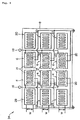
- Fig. 9 is a plan view showing a surface acoustic wave filter according to a third embodiment of the present invention.
- elements identical to those in Fig. 5 are designated by the same reference numerals and symbols.
- This surface acoustic wave filter 34 differs from surface acoustic wave filter 26 according to the second embodiment in that a further set of IDTs 4, 6 and a pair of grating reflectors 28, 30 are added in the surface acoustic wave filter 34.
- Electrodes 14 of respective IDTs 4 are all connected to input terminal 16 and electrodes 14 of respective IDTs 6 are all connected to output terminal 18. Also, electrodes 20 of respective IDTs 4, 6 are all grounded.
- the parallel connection of three IDTs 4, 6 in this embodiment enables input and output impedance to be further suppressed as compared with the second embodiment, so that the spurious signal can be suppressed without increasing the input and output impedance.
- piezoelectric substrate 8 is made of the ST cut crystal substrate in the afore mentioned embodiments, lithium tantalate (LiTaO3), lithium niobate (LiNbO3), lithium tetraborate (Li2B4O7) and the like may be used for piezoelectric substrate 8 without being limited to the crystal substrate. Similar effects can be obtained by using those materials.
Abstract
Description
- The present invention relates to a surface acoustic wave filter in which IDTs (Inter Digital Transducer) on an input side and on an output side each made of a plurality of electrode digits are formed on a piezoelectric substrate with a spacing interposed therebetween.
- Fig. 1 is a plan view showing an example of a conventional surface acoustic wave filter. This surface
acoustic wave filter 102 hasIDTs piezoelectric substrate 104 made of crystal and the like. The width of each electrode digit of each ofIDTs electrode 114 ofIDTs input terminal 116 andoutput terminal 118 theother electrodes 120 are both grounded. - In this surface
acoustic wave filter 102, when an alternating signal is supplied frominput terminal 116, IDT 106 causes a surface acoustic wave to be excited onpiezoelectric substrate 104. The wave is propagated in a direction orthogonal to the extending direction of eachelectrode digit 112 constitutingIDT 106, forms a standing wave while repeating multiple reflection betweenIDTS IDT 108 and then outputted fromoutput terminal 118 as an electric signal. - Surface
acoustic wave filter 102 having such construction as described above is also referred to as a vertical mode resonator type surface acoustic wave filter since the surface acoustic wave is propagated in the vertical direction and the resonance of the modes distributed in the same direction as the propagated direction is utilized. - Fig. 2 is a graph showing the frequency characteristic of surface
acoustic wave filter 102. In this figure, the horizontal axis represents the frequency and the vertical axis represents the attenuation factor, respectively. - An ideal characteristic for surface
acoustic wave filter 102 which is a band-pass filter is to pass signals only in the pass-band near the center frequency f. However, signals are actually passed in some degree even at a point away from the center frequency, which phenomenon appears as a spurious signal in the frequency characteristic. - Particularly, in surface
acoustic wave filter 102 which is a vertical mode resonator type surface acoustic wave filter, a typicalspurious signal 122 occurs in a region higher than the center frequency, which causes a reduction in the amount of attenuation out of the band and a deterioration in the frequency characteristic as a band-pass filter. - It is therefore an object of the present invention to provide a surface acoustic wave filter having an improved frequency characteristic by suppressing the occurrence of such a spurious signal typical of the vertical mode resonator type surface acoustic wave filter.
- In order to achieve the above object, in a surface acoustic wave filter according to the present invention, Nε≧0.55 is satisfied where ε is a reflection coefficient of an electrode digit and N is the total number of pairs of the electrode digits constituting IDTs on an input side and on an output side, and fH≦-17.5W+210 is satisfied where W(wavelength) is the aperture width of the surface acoustic wave transmission path formed of the IDTs on the input side and on the output side, f(Hz) is the center frequency of the filter, and H(m) is the thickness of the electrode digits.
- Since the reflection coefficient ε of the electrode digit and the total number N of the pairs of the electrode digits of the IDT are set to satisfy Nε≧0.55 and the aperture width W of the surface acoustic wave transmission path, the center frequency f of the filter, and the thickness H of the electrode digits are set to satisfy fH≦-17.5W+210, bulk mode transformation in the IDT is increased. As a result, the spurious signal typical of the vertical mode resonator type surface acoustic wave filter is suppressed, thereby improving the frequency characteristic as a band-pass filter.
- The above and other objects, features and advantages of the present invention will become apparent from the following description with reference to the accompanying drawings which illustrate examples of the present invention.
- Fig. 1 is a plan view showing an example of a conventional surface acoustic wave filter;
- Fig. 2 is a graph showing the frequency characteristic of the surface acoustic wave filter in Fig. 1;
- Fig. 3 is a plan view of a surface acoustic wave filter according to a first embodiment of the present invention;
- Fig. 4 is a graph showing the frequency characteristic of the surface acoustic wave filter of Fig. 3;
- Fig. 5 is a plan view of a surface acoustic wave filter according to a second embodiment of the present invention;
- Fig. 6 is a graph showing the frequency characteristic of the surface acoustic wave filter of Fig. 5;
- Fig. 7 is a graph showing the frequency characteristics of a conventional surface acoustic wave filter;
- Fig. 8 is a graph showing a relationship between a spurious signal suppressing effect and parameters; and
- Fig. 9 is a plan view of a surface acoustic wave filter according to a third embodiment of the present invention.
-
- Referring now to Fig. 3, surface acoustic wave filter 2 according to a first embodiment of the present invention is a vertical mode resonator type surface acoustic wave filter serving as a band-pass filter and includes
IDTs IDTs piezoelectric substrate 8 with a spacing interposed therebetween. - Each of
IDTs electrode digit 12 is λ/4 where λ is the wavelength of the surface acoustic wave during resonance. Oneelectrodes 14 ofIDTs input terminal 16 andoutput terminal 18, respectively, and theother electrodes 20 are both grounded. - In this embodiment, a reflection coefficient per electrode digit (i.e. acoustic impedance discontinuous coefficient) ε, and the total number N of the pairs of the electrode
digits constituting IDTs - It should be noted that the setting the product of the total number N of the pairs of the electrode digits and the reflection coefficient ε to be 0.55 or more is equivalent to the setting the reflection coefficient of the overall surface waveguide path to be 1.5 or more. This value can be realized with the existing technology in a vertical mode resonator type surface acoustic wave filter having a usual constitution such as surface acoustic wave filter 2 of this embodiment.
- The aperture width W(wavelength) of the surface acoustic wave transmission path formed of
IDTs - In order to satisfy the equation (2), the aperture width W of the surface acoustic wave transmission path is shorter than that of a conventional surface acoustic wave filter when the center frequency f and the thickness H of the electrode digits are those as conventional.
- The basic operation of surface acoustic wave filter 2 constituted as described above is the same as that of conventional surface
acoustic wave filter 10. Specifically, when an alternating signal is supplied frominput terminal 16, IDT 4 causes the surface acoustic wave to be excited onpiezoelectric substrate 8. The wave is propagated in a direction orthogonal to the extending direction of eachelectrode digit 12 constituting IDT, forms a standing wave while repeating multiple reflection betweenIDTs IDT 6 and then outputted fromoutput terminal 18 as an electric signal. - However, in surface acoustic wave filter 2 of this embodiment, the above parameters are set to satisfy the equation (1) and the equation (2) so that the bulk mode transformation in
IDTs - Fig. 4 is a graph showing the frequency characteristic of surface acoustic wave filter 2, in which the horizontal axis represents the frequency and the vertical axis represents the attenuation factor, respectively.
- As can seen from the comparison of Fig. 4 with Fig. 2 showing the frequency characteristic of the conventional surface
acoustic wave filter 102, in surface acoustic wave filter 2 of this embodiment,spurious signal 22 typical of a vertical mode resonator type surface acoustic wave filter occurring on the higher side than the center frequency f is greatly reduced, improving the frequency characteristic as a pass-band filter. In Fig. 4,dotted line 24 represents the level ofspurious signal 122 in the case of the conventional surface acoustic wave filter 102 (Fig. 2). - Referring to Fig. 5, there is shown a surface acoustic wave filter according to a second embodiment of the present invention. In this figure, elements identical to those in Fig. 3 are designated by the same reference numerals and symbols and will not be described in detail herein.
- In this surface
acoustic wave filter 26, a pair ofgrating reflectors piezoelectric substrate 8 tosandwich IDTs IDTs grating reflectors piezoelectric substrate 8. Thesegrating reflectors piezoelectric substrate 8 in this embodiment similarly toIDTS - The aperture width of the surface acoustic wave transmission path formed of
respective grating reflectors IDTs -
Electrodes 14 of therespective IDTs 4 are both connected toinput terminal 16 andelectrodes 14 of therespective IDTs 6 are both connected tooutput terminal 18. On the other hand,electrodes 20 of therespective IDTs 4 andelectrodes 20 of therespective IDTs 6 are both grounded. - In surface
acoustic wave filter 26 of the second embodiment, to satisfy the equations (1), (2), the product Nε of the total number N of the pairs ofelectrode digits 12 and a reflection coefficient ε per electrode digit is set to be 3.9, the product fH of the center frequency f and the thickness H ofelectrode digits 12 is set to be 70, and the aperture width W of the surface acoustic waveguide path is set to be 5.5(wavelength), respectively. - In surface
acoustic wave filter 26 of the second embodiment constructed above, when an alternating signal is supplied frominput terminal 16, eachIDT 4 causes a surface acoustic wave to be excited onpiezoelectric substrate 8. The wave is propagated in a direction orthogonal to the extending direction of eachelectrode digit 12 constitutingIDT 4, forms a standing wave while repeating multiple reflection betweenIDTs grating reflectors IDT 6 and then outputted fromoutput terminal 18 as an electric signal. - Fig. 6 is a graph showing the frequency characteristic of the surface acoustic wave filter of the second embodiment. Fig. 7 is a graph showing the frequency characteristics of a conventional surface acoustic wave filter. In each of these figures, the horizontal axis represents the frequency and the vertical axis represents the attenuation factor. In the conventional surface acoustic wave filter, the aperture width of the surface acoustic wave transmission path is set to be 11(wavelength) (i.e. 5.5×2) to obtain the same condition as that of surface
acoustic wave filter 26 of the second embodiment. - Comparison between the levels of the spurious signals occurring near arrows A, B respectively in Fig. 6 and Fig. 7, shows that the spurious signals are suppressed by 10 dB or more in the frequency characteristic of surface
acoustic wave filter 26 of this embodiment shown in Fig. 6 as compared with that in the conventional case in Fig. 7, thereby revealing that the characteristic of surfaceacoustic wave filter 26 as a band-pass filter is significantly improved. - The parallel connection of two
IDTs - In order to clarify how the parameters are set to obtain the spurious signal suppressing effect in the surface acoustic wave filter having a construction such as surface
acoustic wave filter 26, various surface acoustic wave filters having different parameters were actually made and the levels of the spurious signals were investigated. - Fig. 8 is a graph showing the result of the investigation. In the graph, the horizontal axis represents the aperture width W and the vertical axis represents the product of the center frequency f and the thickness H of the electrode digits. The O marks and X marks in the graph respectively correspond to the surface acoustic wave filters made. The O marks indicate that the level of the spurious signal was suppressed by 3 dB or more as compared with conventional case (i.e. suppressed to 1/2 or less) and the X marks indicate that such a suppression effect was not obtained.
- As can be seen from the graph of Fig. 8, all of the O marks exist on
straight line 32 or on the left hand ofstraight line 32 while the X marks exist on the right hand ofstraight line 32. Thus, it is shown that the suppression effect of the spurious signal can be sufficiently obtained onstraight line 32 or on the left hand ofstraight line 32 while a sufficient suppression effect of the spurious can not be obtained on the right hand ofstraight line 32. Thisstraight line 32 is represented by fH=-17.5W+210. Therefore, the spurious signal can be suppressed by setting the aperture width W, the center frequency f, and the thickness H of the electrode digits so as to satisfy the equation (2). - Fig. 9 is a plan view showing a surface acoustic wave filter according to a third embodiment of the present invention. In the figure, elements identical to those in Fig. 5 are designated by the same reference numerals and symbols.
- This surface
acoustic wave filter 34 differs from surfaceacoustic wave filter 26 according to the second embodiment in that a further set ofIDTs grating reflectors acoustic wave filter 34. -
Electrodes 14 ofrespective IDTs 4 are all connected to input terminal 16 andelectrodes 14 ofrespective IDTs 6 are all connected tooutput terminal 18. Also,electrodes 20 ofrespective IDTs - The parallel connection of three
IDTs - Although
piezoelectric substrate 8 is made of the ST cut crystal substrate in the afore mentioned embodiments, lithium tantalate (LiTaO3), lithium niobate (LiNbO3), lithium tetraborate (Li2B4O7) and the like may be used forpiezoelectric substrate 8 without being limited to the crystal substrate. Similar effects can be obtained by using those materials.
Claims (8)
- A surface acoustic wave filter comprising:IDTs on an input side and on an output side each including a plurality of a pairs of electrode digits, said IDTs being formed on a piesoelectric substrate with a spacing interposed therebetween,
wherein Nε≧0.55 is satisfied where ε is a reflection coefficient of the electrode digit and N is the total number of the pairs of the electrode digits constituting said IDTs on the input side and on the output side, and
wherein fH≦-17.5W+210 is satisfied where W(wavelength) is an aperture width of a surface acoustic wave transmission path formed of said IDTs on the input side and on the output side, f(Hz) is the center frequency of said filter, and H(m) is the thickness of the electrode digits. - The surface acoustic wave filter according to claim 1, further comprising a pair of grating reflectors formed on the piezoelectric substrate to sandwich said IDTs on the input side and on the output side therebetween.
- The surface acoustic wave filter according to claim 1 or 2, wherein a plurality of sets of said IDTs on the input side and on the output side and said pair of grating reflectors are formed on the piezoelectric substrate and wherein said IDTs on the input side are electrically connected in parallel to each other and said IDTs on the output side are electrically connected in parallel to each other.
- The surface acoustic wave filter according to claim 3, wherein two or three sets of said IDTs on the input side and on the output side and said pair of grating reflectors are formed on the piezoelectric substrate.
- The SAW filter according to claim 1, 2, 3 or 4, wherein the piezoelectric substrate is formed of a crystal.
- The SAW filter according to any one of claims 1 to 5, wherein the piezoelectric substrate is formed of lithium tantalate, lithium niobate or lithium tetraborate.
- The surface acoustic wave filter according to claim 5 or 6, wherein the piezoelectric substrate is an ST cut crystal substrate.
- The SAW filter according to any one of claims 1 to 7, wherein the electrode digit is made of aluminum or of an alloy if aluminum.
Applications Claiming Priority (2)
| Application Number | Priority Date | Filing Date | Title |
|---|---|---|---|
| JP2031398 | 1998-01-16 | ||
| JP10020313A JP3137064B2 (en) | 1998-01-16 | 1998-01-16 | Surface acoustic wave filter |
Publications (2)
| Publication Number | Publication Date |
|---|---|
| EP0930703A2 true EP0930703A2 (en) | 1999-07-21 |
| EP0930703A3 EP0930703A3 (en) | 2000-12-27 |
Family
ID=12023656
Family Applications (1)
| Application Number | Title | Priority Date | Filing Date |
|---|---|---|---|
| EP99100368A Withdrawn EP0930703A3 (en) | 1998-01-16 | 1999-01-15 | Surface acoustic wave filter having improved frequency characteristic |
Country Status (3)
| Country | Link |
|---|---|
| US (1) | US6049260A (en) |
| EP (1) | EP0930703A3 (en) |
| JP (1) | JP3137064B2 (en) |
Families Citing this family (7)
| Publication number | Priority date | Publication date | Assignee | Title |
|---|---|---|---|---|
| WO2002001715A1 (en) * | 2000-06-27 | 2002-01-03 | Kabushiki Kaisha Toshiba | Surface acoustic wave device |
| EP1303041B1 (en) | 2001-10-16 | 2009-03-18 | Panasonic Corporation | Interdigital transducer, surface acoustic wave filter and radio communication apparatus |
| CN1947334B (en) * | 2004-04-28 | 2011-09-21 | 松下电器产业株式会社 | Elasticity surface wave resonator and elasticity surface wave filter using it |
| US10135422B2 (en) * | 2015-10-01 | 2018-11-20 | Skyworks Filter Solutions Japan Co., Ltd. | Filter devices having improved attenuation characteristics |
| US10404234B2 (en) | 2016-09-02 | 2019-09-03 | Skyworks Filter Solutions Japan Co., Ltd. | Filter device with phase compensation, and electronic devices including same |
| JP2018088678A (en) | 2016-11-29 | 2018-06-07 | スカイワークス ソリューションズ, インコーポレイテッドSkyworks Solutions, Inc. | Filters including loop circuits for phase cancellation |
| US11038487B2 (en) | 2018-07-18 | 2021-06-15 | Skyworks Solutions, Inc. | FBAR filter with integrated cancelation circuit |
Citations (4)
| Publication number | Priority date | Publication date | Assignee | Title |
|---|---|---|---|---|
| JPS63194406A (en) * | 1987-02-09 | 1988-08-11 | Hitachi Ltd | Surface acoustic wave resonator |
| JPH03296316A (en) * | 1990-04-13 | 1991-12-27 | Nikko Kyodo Co Ltd | Surface acoustic wave resonance filter |
| WO1996010293A1 (en) * | 1994-09-29 | 1996-04-04 | Seiko Epson Corporation | Saw device |
| US5663696A (en) * | 1994-04-25 | 1997-09-02 | Advanced Saw Products Sa | Saw filter with wave reflections and phase differences |
Family Cites Families (10)
| Publication number | Priority date | Publication date | Assignee | Title |
|---|---|---|---|---|
| JPH0773177B2 (en) * | 1984-12-17 | 1995-08-02 | 株式会社東芝 | Surface acoustic wave resonator |
| JPH071859B2 (en) * | 1988-03-11 | 1995-01-11 | 国際電気株式会社 | Surface acoustic wave filter |
| JPH04259109A (en) * | 1991-02-13 | 1992-09-14 | Seiko Epson Corp | Two-port saw resonator |
| JP3160918B2 (en) * | 1991-02-20 | 2001-04-25 | セイコーエプソン株式会社 | Surface acoustic wave filter |
| JP3126416B2 (en) * | 1991-06-26 | 2001-01-22 | キンセキ株式会社 | Surface acoustic wave device |
| JPH05121996A (en) * | 1991-10-30 | 1993-05-18 | Nikko Kyodo Co Ltd | Surface acoustic wave filter |
| JP3001350B2 (en) * | 1993-05-19 | 2000-01-24 | 日本電気株式会社 | Surface acoustic wave filter |
| US5365138A (en) * | 1993-12-02 | 1994-11-15 | Northern Telecom Limited | Double mode surface wave resonators |
| US5568001A (en) * | 1994-11-25 | 1996-10-22 | Motorola, Inc. | Saw device having acoustic elements with diverse mass loading and method for forming same |
| JP3224202B2 (en) * | 1996-11-28 | 2001-10-29 | 富士通株式会社 | Surface acoustic wave device |
-
1998
- 1998-01-16 JP JP10020313A patent/JP3137064B2/en not_active Expired - Fee Related
-
1999
- 1999-01-15 EP EP99100368A patent/EP0930703A3/en not_active Withdrawn
- 1999-01-15 US US09/231,657 patent/US6049260A/en not_active Expired - Lifetime
Patent Citations (4)
| Publication number | Priority date | Publication date | Assignee | Title |
|---|---|---|---|---|
| JPS63194406A (en) * | 1987-02-09 | 1988-08-11 | Hitachi Ltd | Surface acoustic wave resonator |
| JPH03296316A (en) * | 1990-04-13 | 1991-12-27 | Nikko Kyodo Co Ltd | Surface acoustic wave resonance filter |
| US5663696A (en) * | 1994-04-25 | 1997-09-02 | Advanced Saw Products Sa | Saw filter with wave reflections and phase differences |
| WO1996010293A1 (en) * | 1994-09-29 | 1996-04-04 | Seiko Epson Corporation | Saw device |
Non-Patent Citations (2)
| Title |
|---|
| PATENT ABSTRACTS OF JAPAN vol. 012, no. 476 (E-693), 13 December 1988 (1988-12-13) & JP 63 194406 A (HITACHI LTD), 11 August 1988 (1988-08-11) * |
| PATENT ABSTRACTS OF JAPAN vol. 016, no. 134 (E-1185), 6 April 1992 (1992-04-06) & JP 03 296316 A (NIPPON MINING CO LTD), 27 December 1991 (1991-12-27) * |
Also Published As
| Publication number | Publication date |
|---|---|
| JP3137064B2 (en) | 2001-02-19 |
| EP0930703A3 (en) | 2000-12-27 |
| JPH11205081A (en) | 1999-07-30 |
| US6049260A (en) | 2000-04-11 |
Similar Documents
| Publication | Publication Date | Title |
|---|---|---|
| EP0633660B1 (en) | Surface acoustic wave filter | |
| US7741931B2 (en) | Acoustic wave device, resonator and filter | |
| US7573178B2 (en) | Acoustic wave device, resonator and filter | |
| US7646266B2 (en) | Surface acoustic wave resonator and surface acoustic wave filter using the same | |
| JPH08265087A (en) | Surface acoustic wave filter | |
| US5977686A (en) | Surface acoustic wave filter | |
| US6346864B1 (en) | Saw resonator filter and duplexer utilizing SH waves, substrate edge reflection, and sub-interdigital transducer portions | |
| US7042313B2 (en) | Surface acoustic wave device and communication device using the same | |
| US6650206B2 (en) | Surface acoustic wave filter and communication apparatus with the same | |
| US6297713B1 (en) | Surface acoustic wave device with split electrodes and outermost electrodes of a different width than the split electrodes | |
| US6049260A (en) | Surface acoustic wave filter having parameters optimized to suppress spurious signals | |
| JP6949552B2 (en) | SAW filter and multiplexer | |
| US6720847B2 (en) | Longitudinally-coupled resonator surface acoustic wave filter and communication apparatus using the same | |
| EP0763889B1 (en) | Surface acoustic wave filter | |
| KR19980019102A (en) | Surface acoustic wave resonator filter | |
| JP4821079B2 (en) | Comb electrode section for surface acoustic wave, surface acoustic wave device, communication device | |
| JP4053038B2 (en) | Surface acoustic wave device | |
| US6147574A (en) | Unidirectional surface acoustic wave transducer and transversal-type saw filter having the same | |
| EP0800270B1 (en) | Surface acoustic wave filter | |
| JP2748009B2 (en) | Surface acoustic wave resonator filter | |
| US6781282B1 (en) | Longitudinally coupled resonator-type surface acoustic wave device | |
| JPH08316773A (en) | Surface acoustic wave device | |
| JP4548305B2 (en) | Dual-mode surface acoustic wave filter | |
| US20200313651A1 (en) | Multiplexer | |
| WO2022091582A1 (en) | Elastic wave filter |
Legal Events
| Date | Code | Title | Description |
|---|---|---|---|
| PUAI | Public reference made under article 153(3) epc to a published international application that has entered the european phase |
Free format text: ORIGINAL CODE: 0009012 |
|
| AK | Designated contracting states |
Kind code of ref document: A2 Designated state(s): DE FR GB |
|
| AX | Request for extension of the european patent |
Free format text: AL;LT;LV;MK;RO;SI |
|
| PUAL | Search report despatched |
Free format text: ORIGINAL CODE: 0009013 |
|
| AK | Designated contracting states |
Kind code of ref document: A3 Designated state(s): AT BE CH CY DE DK ES FI FR GB GR IE IT LI LU MC NL PT SE |
|
| AX | Request for extension of the european patent |
Free format text: AL;LT;LV;MK;RO;SI |
|
| 17P | Request for examination filed |
Effective date: 20001116 |
|
| AKX | Designation fees paid |
Free format text: DE FR GB |
|
| RAP1 | Party data changed (applicant data changed or rights of an application transferred) |
Owner name: NRS TECHNOLOGIES INC. |
|
| RAP1 | Party data changed (applicant data changed or rights of an application transferred) |
Owner name: NIHON DEMPA KOGYO CO., LTD. |
|
| 17Q | First examination report despatched |
Effective date: 20071102 |
|
| STAA | Information on the status of an ep patent application or granted ep patent |
Free format text: STATUS: THE APPLICATION IS DEEMED TO BE WITHDRAWN |
|
| 18D | Application deemed to be withdrawn |
Effective date: 20110802 |