EP0930686A1 - Wiring box with shielded water outlet - Google Patents
Wiring box with shielded water outlet Download PDFInfo
- Publication number
- EP0930686A1 EP0930686A1 EP99100720A EP99100720A EP0930686A1 EP 0930686 A1 EP0930686 A1 EP 0930686A1 EP 99100720 A EP99100720 A EP 99100720A EP 99100720 A EP99100720 A EP 99100720A EP 0930686 A1 EP0930686 A1 EP 0930686A1
- Authority
- EP
- European Patent Office
- Prior art keywords
- box
- closure
- outlet
- wall
- wiring box
- Prior art date
- Legal status (The legal status is an assumption and is not a legal conclusion. Google has not performed a legal analysis and makes no representation as to the accuracy of the status listed.)
- Withdrawn
Links
- XLYOFNOQVPJJNP-UHFFFAOYSA-N water Substances O XLYOFNOQVPJJNP-UHFFFAOYSA-N 0.000 title claims abstract description 48
- 230000001681 protective effect Effects 0.000 claims abstract description 7
- 238000004078 waterproofing Methods 0.000 description 4
- 230000007812 deficiency Effects 0.000 description 1
- 230000004048 modification Effects 0.000 description 1
- 238000012986 modification Methods 0.000 description 1
- 230000002265 prevention Effects 0.000 description 1
Images




Classifications
-
- H—ELECTRICITY
- H02—GENERATION; CONVERSION OR DISTRIBUTION OF ELECTRIC POWER
- H02G—INSTALLATION OF ELECTRIC CABLES OR LINES, OR OF COMBINED OPTICAL AND ELECTRIC CABLES OR LINES
- H02G3/00—Installations of electric cables or lines or protective tubing therefor in or on buildings, equivalent structures or vehicles
- H02G3/02—Details
- H02G3/08—Distribution boxes; Connection or junction boxes
- H02G3/088—Dustproof, splashproof, drip-proof, waterproof, or flameproof casings or inlets
Definitions
- the present Invention is directed to a wiring box, particularly for use in automobiles, which has provision for preventing water from entering and, at the same time, allowing water within to drain out.
- Wiring boxes 60 and 65 are used to connect various electrical elements, particularly in a vehicle such as an automobile.
- Covers 62 are provided on main boxes 61 and 66, respectively, for prevention of water seepage.
- wiring box 60 (Figure 18) has water outlet 63 in its bottom surface.
- wall 68 is provided within main box 61 just within water outlet 67.
- an object of the present Invention to provide improved waterproofing by minimizing the opportunity for water from the outside to enter the box and, at the same time, to prevent internal wires from being damaged.
- the present Invention includes a wire box comprising a main box having an outer surface with a water outlet therein. There is a wall adjacent the periphery of the outlet which projects in a direction away from the surface. On the end of the wall farthest from the main box is a closure which is thereby spaced apart from the main box. At least one opening is provided in the wall which communicates with the outlet and the exterior of the main box.
- Protective ribs are located near each of the openings and spaced apart therefrom in a direction parallel to the surface.
- the ribs can surround the entire wall.
- a plurality of openings may be provided in the wall, each communicating with the outlet and the exterior of the box.
- the surface is at the bottom of the main box and a section thereof is slanted in the direction of the outlet. This facilitates the draining of water out of the box.
- a central portion of the closure is raised upward so that it is higher than at least a portion of the perimeter of the closure. Thus, the closure slopes toward the opening(s).
- the height of the rib(s) perpendicular to the surface is greater than the width of the opening in the same direction.
- wiring box 10 of the present Invention comprises main box 11 and a cover 12. Integral with main box 11 are wall 17 and closure 18 which form a cavity. Wall 17 symmetrically surrounds water outlet 14 and closure 18 is separated by a distance therefrom. A pair of openings 20, communicating between water outlet 14 and the exterior of main box 11, is formed in wall 17. Rib 19, preferably four-sided, projects from outer surface 13 of main box 11. Preferably, height h1 of rib 14 is greater than height h2 of openings 20.
- the wiring box in accordance with the present Invention permits water entering main box 11 (such as during a car wash) to drain by passing through water outlet 14 and openings 20.
- the protection formed by walls 17 and closure 18 serve to make it very difficult for water below outlet 11 to pass through the outlet and enter main box 11.
- rib 19 impedes water droplets attempting to enter water outlet 14 from below the outlet at an angle thereto.
- slanted surface 27 directs any water to water outlet 14 and through openings 20.
- Closure 18 prevents entry of water from directly below and ribs 19 prevent entry of water at an angle. This configuration permits water to drain out of the box more readily.
- closure 18 is designed so that elevated central portion 30 is closer to water outlet 14 than the rest of the closure. This further assists the water to drain out of the box.
- Figure 11 shows a box of the present Invention wherein water outlet 14 in outer surface 13 is provided with closure 18.
- Wall 17 has only a single opening 20 and rib 19 is located adjacent thereto. On the other side of wall 17, there is no opening and rib 19 adjacent thereto may be omitted if desired.
- bottom 25 of main box 11 is provided with shielding member 16 wherein closure 45, affixed to supports 44, is in the shape of a cross. This permits water which has entered main box 11 to pass through water outlet 14 and openings 46, thereby draining main box 11.
- rib 19 surrounds water outlet 14 and is spaced apart therefrom. This provides an added measure of protection against water being splashed into main box 11.
- the Invention as shown in Figures 14 to 17 includes shielding member 51 which comprises supports 52 and 53, closure 54, and openings 55.
- the present Invention possesses a number of advantages over the prior art wiring boxes as shown in Figures 18 and 19. Since closure 18 and wall 17 are disposed outside main box 11, they do not interfere with wires or any other elements within the box. This reduces opportunity for damage during assembly and thereafter. Furthermore, this makes it more difficult for water droplets from directly below to enter the wiring box and hence makes the waterproofing more reliable. If ribs 19 are also provided, this impedes the entry of water even if it comes from below at an angle. If the height of rib 19 is greater than the width of opening 20, it becomes still more difficult for water droplets to enter main box 11. Of course, if only one opening 20 is provided (as in Figure 11), this increases the reliability of the waterproofing and makes it still more difficult for water to enter the box.
- water outlets 14 have been shown as being rectangular, it is within the contemplation of the present Invention that these openings could be of any shape, including circular and triangular.
- the wiring box may be provided with a plurality of shielding members, rather than the single such member specifically described herein.
- the openings leading from the water outlet to the exterior of the main box are not directly under the water outlet. In this way, water splashing into the box is either minimized or avoided.
- the height of the ribs be such that they extend, in a direction perpendicular to the bottom of the box, beyond the openings through which water passes. This adds to the waterproofing ability of the device.
Landscapes
- Engineering & Computer Science (AREA)
- Architecture (AREA)
- Civil Engineering (AREA)
- Structural Engineering (AREA)
- Connection Or Junction Boxes (AREA)
- Connector Housings Or Holding Contact Members (AREA)
Abstract
A wire box including a main box having an outer surface with
a water outlet therein. A wall is provided around the periphery of
the outlet and projects outwardly from the surface in a direction
substantially perpendicular thereto. There is a closure on the end
of the wall furthest from the main box. There is at least one
opening in the wall which communicates between the outlet and the
exterior of the box. It is more desirable if there is a protective
rib adjacent the opening and spaced apart therefrom a distant
sufficient to allow water to run out of the opening. The form of
the closure may be widely varied so that there is no direct path
into and out of the main box for water to follow.
Description
- The present Invention is directed to a wiring box, particularly for use in automobiles, which has provision for preventing water from entering and, at the same time, allowing water within to drain out.
- Typical wiring boxes of the prior art are shown in Figures 18 and 19.
Wiring boxes Covers 62 are provided onmain boxes water outlet 63 in its bottom surface. Alternatively, in Figure 19,wall 68 is provided withinmain box 61 just withinwater outlet 67. - However, the foregoing wiring boxes have certain serious deficiencies. Water can enter the boxes through the water outlets, especially when the vehicle is being washed. Moreover, as can be seen in Figure 19,
wall 68 is located insidemain box 66. As a result, it reduces the space available and can interfere with and damage the wiring therein. - It is, therefore, an object of the present Invention to provide improved waterproofing by minimizing the opportunity for water from the outside to enter the box and, at the same time, to prevent internal wires from being damaged.
- The present Invention includes a wire box comprising a main box having an outer surface with a water outlet therein. There is a wall adjacent the periphery of the outlet which projects in a direction away from the surface. On the end of the wall farthest from the main box is a closure which is thereby spaced apart from the main box. At least one opening is provided in the wall which communicates with the outlet and the exterior of the main box.
- Protective ribs are located near each of the openings and spaced apart therefrom in a direction parallel to the surface. Advantageously, the ribs can surround the entire wall. Also, a plurality of openings may be provided in the wall, each communicating with the outlet and the exterior of the box. There is a protective rib adjacent each such opening. In a particularly preferred form of the device, there are two openings, diametrically opposite each other and ribs corresponding thereto.
- Usefully, the surface is at the bottom of the main box and a section thereof is slanted in the direction of the outlet. This facilitates the draining of water out of the box. Alternatively, a central portion of the closure is raised upward so that it is higher than at least a portion of the perimeter of the closure. Thus, the closure slopes toward the opening(s).
- It is of particular value if the height of the rib(s) perpendicular to the surface is greater than the width of the opening in the same direction.
- In the accompanying drawings, constituting a part hereof, and in which like reference characters indicate like parts,
- Figure 1
- is a perspective view showing the wiring box from the bottom;
- Figure 2
- is an enlarged bottom view of the rib, wall, and closure;
- Figure 3
- is a cross section along the line 3-3 of Figure 2;
- Figure 4
- is a cross section along the line 4-4 of figure 2;
- Figure 5
- is a view, similar to that of Figure 2, of a preferred form of the Invention;
- Figure 6
- is a cross section along line 6-6 of Figure 5;
- Figure 7
- is a cross section, similar to that of Figure 6, showing the slanted bottom surface;
- Figure 8
- is a cross section, similar to that of Figure 4, of the device of Figure 7;
- Figure 9
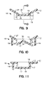
- is a cross section, similar to that of Figure 8, showing the closure with an elevated central portion;
- Figure 10
- is a section perpendicular to that of Figure 9;
- Figure 11
- is a cross section, similar to that of Figure 2, of a device having only a single opening;
- Figure 12
- is a perspective view wherein the closure is cruciform in shape;
- Figure 13
- is a view, similar to that of Figure 12, wherein the cruciform closure is surrounded by a rib;
- Figure 14
- is a view, similar to that of Figure 13, wherein the closure has been modified;
- Figure 15
- is a cross section along line 15-15 of Figure 14;
- Figure 16
- is a cross section along line 16-16 of Figure 14;
- Figure 17
- is a cross section along line 17-17 of Figure 14;
- Figure 18
- is a partial section showing a wiring box of the prior art; and
- Figure 19
- is a view, similar to that of Figure 12, of another prior art wiring box.
- As shown, for example, in Figures 1 to 4,
wiring box 10 of the present Invention comprisesmain box 11 and acover 12. Integral withmain box 11 arewall 17 andclosure 18 which form a cavity.Wall 17 symmetrically surroundswater outlet 14 andclosure 18 is separated by a distance therefrom. A pair ofopenings 20, communicating betweenwater outlet 14 and the exterior ofmain box 11, is formed inwall 17.Rib 19, preferably four-sided, projects fromouter surface 13 ofmain box 11. Preferably, height h1 ofrib 14 is greater than height h2 ofopenings 20. - The wiring box in accordance with the present Invention permits water entering main box 11 (such as during a car wash) to drain by passing through
water outlet 14 andopenings 20. The protection formed bywalls 17 andclosure 18 serve to make it very difficult for water belowoutlet 11 to pass through the outlet and entermain box 11. Moreover,rib 19 impedes water droplets attempting to enterwater outlet 14 from below the outlet at an angle thereto. - In Figures 5 and 6,
water outlet 14 inouter surface 13,wall 17 withopenings 20, andclosure 18 are all as shown in Figure 2.Ribs 19 are provided onlyadjacent openings 20 rather than completely surroundingwater outlet 14. - In Figures 7 and 8, slanted
surface 27 directs any water towater outlet 14 and throughopenings 20.Closure 18 prevents entry of water from directly below andribs 19 prevent entry of water at an angle. This configuration permits water to drain out of the box more readily. As shown in Figures 9 and 10,closure 18 is designed so that elevatedcentral portion 30 is closer towater outlet 14 than the rest of the closure. This further assists the water to drain out of the box. Figure 11 shows a box of the present Invention whereinwater outlet 14 inouter surface 13 is provided withclosure 18.Wall 17 has only asingle opening 20 andrib 19 is located adjacent thereto. On the other side ofwall 17, there is no opening andrib 19 adjacent thereto may be omitted if desired. - As can be best seen in Figure 12, bottom 25 of
main box 11 is provided with shieldingmember 16 whereinclosure 45, affixed tosupports 44, is in the shape of a cross. This permits water which has enteredmain box 11 to pass throughwater outlet 14 andopenings 46, thereby drainingmain box 11. - In a preferred form of the Invention (see Figure 13),
rib 19 surroundswater outlet 14 and is spaced apart therefrom. This provides an added measure of protection against water being splashed intomain box 11. - The Invention as shown in Figures 14 to 17 includes shielding
member 51 which comprisessupports closure 54, andopenings 55. - The present Invention possesses a number of advantages over the prior art wiring boxes as shown in Figures 18 and 19. Since
closure 18 andwall 17 are disposed outsidemain box 11, they do not interfere with wires or any other elements within the box. This reduces opportunity for damage during assembly and thereafter. Furthermore, this makes it more difficult for water droplets from directly below to enter the wiring box and hence makes the waterproofing more reliable. Ifribs 19 are also provided, this impedes the entry of water even if it comes from below at an angle. If the height ofrib 19 is greater than the width ofopening 20, it becomes still more difficult for water droplets to entermain box 11. Of course, if only oneopening 20 is provided (as in Figure 11), this increases the reliability of the waterproofing and makes it still more difficult for water to enter the box. - Although a limited number of aspects of the present Invention have been expressly disclosed, such modifications as would be apparent to the person of ordinary skill may be made without departing from the scope or spirit thereof. Although
water outlets 14 have been shown as being rectangular, it is within the contemplation of the present Invention that these openings could be of any shape, including circular and triangular. Moreover, the wiring box may be provided with a plurality of shielding members, rather than the single such member specifically described herein. In essence, it is a feature of the present Invention that the openings leading from the water outlet to the exterior of the main box are not directly under the water outlet. In this way, water splashing into the box is either minimized or avoided. It is preferable that the height of the ribs be such that they extend, in a direction perpendicular to the bottom of the box, beyond the openings through which water passes. This adds to the waterproofing ability of the device. - Although only a limited number of aspects of the present Invention have been expressly disclosed, it is, nonetheless, to be broadly construed, and not to be limited except by the character of the claims appended hereto.
Claims (12)
- A wiring box (10) comprising a main box (11) having an outer surface (13) with a water outlet (14) therein, a shielding member (16) thereon, said shielding member comprising a wall (17) at least partly surrounding a periphery of said outlet and projecting in an external direction from said surface, a closure (18) on an end of said wall remote from said main box, whereby said closure is spaced apart from said main box in said external direction, at least one opening (20, 46) in said wall in communication with said outlet and an exterior of said main box.
- The wiring box of Claim 1 wherein said wall extends around said periphery of said outlet.
- The wiring box of Claim 1 comprising at least one protective rib (19) adjacent said opening and spaced apart therefrom in a rib direction parallel to said surface.
- The wiring box of Claim 1 wherein said rib surrounds said wall.
- The wiring box of Claim 1 comprising a plurality of said openings in said wall, each of said openings being in communication with said outlet and said exterior of said main box, one said protective rib being adjacent each of said openings.
- The wiring box of Claim 4 wherein there are two said openings opposite each other.
- The wiring box of Claim 1 wherein said main box has an inner surface (27) and at its bottom (25), a section of said inner surface being slanted toward said outlet.
- The wiring box of Claim 1 wherein an elevated portion of said closure is closer to said water outlet than at least a part of a perimeter of said closure, thereby forming a slope toward at least one said opening.
- The wiring box of Claim 1 wherein said rib has a first height in said external direction greater than a second height of said opening in said external direction.
- The wiring box of Claim 1 wherein said closure is in the form of a cross, said wall comprising supports (44), each of which extends from said bottom to an end of said cross, whereby said closure, said supports, and said outlet form each said opening.
- The wiring box of Claim 10 comprising a protective rib adjacent each said opening and spaced apart therefrom in a rib direction parallel to said surface.
- The wiring box of Claim 1 wherein said shielding member comprises said wall in the form of supports adjacent said outlet, said closure on ends of said supports and covering said water outlet, said closure having a narrow portion between widened portions, whereby said supports function as protective ribs.
Priority Applications (1)
| Application Number | Priority Date | Filing Date | Title |
|---|---|---|---|
| DE29924185U DE29924185U1 (en) | 1998-01-16 | 1999-01-15 | Cable box with protected water outlet opening |
Applications Claiming Priority (4)
| Application Number | Priority Date | Filing Date | Title |
|---|---|---|---|
| JP664798 | 1998-01-16 | ||
| JP664798 | 1998-01-16 | ||
| JP32494798 | 1998-11-16 | ||
| JP10324947A JPH11266516A (en) | 1998-01-16 | 1998-11-16 | Distribution box |
Publications (1)
| Publication Number | Publication Date |
|---|---|
| EP0930686A1 true EP0930686A1 (en) | 1999-07-21 |
Family
ID=26340834
Family Applications (1)
| Application Number | Title | Priority Date | Filing Date |
|---|---|---|---|
| EP99100720A Withdrawn EP0930686A1 (en) | 1998-01-16 | 1999-01-15 | Wiring box with shielded water outlet |
Country Status (4)
| Country | Link |
|---|---|
| US (1) | US6166327A (en) |
| EP (1) | EP0930686A1 (en) |
| JP (1) | JPH11266516A (en) |
| CN (1) | CN1226097A (en) |
Cited By (7)
| Publication number | Priority date | Publication date | Assignee | Title |
|---|---|---|---|---|
| US6737578B2 (en) | 2002-07-09 | 2004-05-18 | Sumitomo Wiring Systems, Ltd. | Electric connection box |
| US6787698B2 (en) | 2002-07-09 | 2004-09-07 | Sumitomo Wiring Systems, Ltd. | Drainage structure of electric parts accommodation box |
| DE102010003257A1 (en) * | 2010-03-25 | 2011-09-29 | Bayerische Motoren Werke Aktiengesellschaft | Device for condensate removal for a closed to the environment housing a motor vehicle, housing and motor vehicle |
| DE10336429B4 (en) * | 2003-08-08 | 2011-12-22 | Abb Ag | Splash-proof, electrical surface-mounted installation device |
| DE10349487B4 (en) * | 2002-11-12 | 2018-06-07 | Yazaki Corporation | Waterproof cover assembly for an electrical junction box |
| EP3823116A1 (en) * | 2019-11-18 | 2021-05-19 | Yazaki Corporation | Liquid discharge structure |
| DE112014007161B4 (en) | 2014-11-12 | 2024-05-02 | Sumitomo Wiring Systems, Ltd. | Protective tube for electrical cable and wiring harness |
Families Citing this family (28)
| Publication number | Priority date | Publication date | Assignee | Title |
|---|---|---|---|---|
| TW497812U (en) * | 2000-02-24 | 2002-08-01 | Delta Electronics Inc | Fixing device |
| JP4099424B2 (en) * | 2003-04-22 | 2008-06-11 | 矢崎総業株式会社 | Busbar positioning structure and electrical junction box |
| JP4593320B2 (en) * | 2005-03-07 | 2010-12-08 | 古河電気工業株式会社 | Drainage structure of electrical junction box |
| US7875798B2 (en) * | 2007-02-16 | 2011-01-25 | Anthony Isaac Funk | Rain shielded box for exiting through siding |
| US7358440B1 (en) * | 2007-02-16 | 2008-04-15 | Anthony Isaac Funk | Rain shielded box for exiting through siding |
| JP4413945B2 (en) * | 2007-04-27 | 2010-02-10 | 古河電気工業株式会社 | Electrical junction box drainage structure |
| JP5146113B2 (en) * | 2008-05-30 | 2013-02-20 | 住友電装株式会社 | Electrical junction box |
| JP5151701B2 (en) * | 2008-06-03 | 2013-02-27 | 住友電装株式会社 | Drainage structure of wire harness |
| JP5719535B2 (en) * | 2010-07-02 | 2015-05-20 | 矢崎総業株式会社 | Waterproof case |
| JP5741945B2 (en) * | 2011-09-14 | 2015-07-01 | 住友電装株式会社 | Electrical junction box |
| JP2013066332A (en) * | 2011-09-20 | 2013-04-11 | Sumitomo Wiring Syst Ltd | Electric connection box |
| CN103107453B (en) * | 2011-11-10 | 2015-09-09 | 富士康(昆山)电脑接插件有限公司 | Electric connector |
| JP5811464B2 (en) * | 2012-05-14 | 2015-11-11 | 住友電装株式会社 | Electrical junction box |
| JP5563629B2 (en) * | 2012-08-07 | 2014-07-30 | ファナック株式会社 | Attachment to prevent liquid from adhering to electronic components |
| JP5935752B2 (en) * | 2013-05-07 | 2016-06-15 | 住友電装株式会社 | Electrical junction box |
| JP6145771B2 (en) * | 2013-06-20 | 2017-06-14 | 矢崎総業株式会社 | Wire harness |
| JP6150068B2 (en) * | 2013-10-23 | 2017-06-21 | Smk株式会社 | connector |
| JP1532486S (en) * | 2014-11-25 | 2015-08-31 | ||
| US10383244B2 (en) * | 2017-03-22 | 2019-08-13 | Regal Beloit America, Inc. | Electronics enclosure assembly and methods of forming the same |
| JP6691073B2 (en) * | 2017-04-25 | 2020-04-28 | 矢崎総業株式会社 | Electrical connection box and wire harness |
| JP6825534B2 (en) * | 2017-10-19 | 2021-02-03 | 住友電装株式会社 | Cover structure and electrical junction box |
| US10177509B1 (en) | 2018-02-14 | 2019-01-08 | Mark Gilstrap | Electrical receptacle mounting preventive of water ingress |
| US11183824B2 (en) | 2018-02-14 | 2021-11-23 | Mark Gilstrap | Electrical box mounting structure preventive of water ingress |
| JP7067368B2 (en) * | 2018-08-24 | 2022-05-16 | 住友電装株式会社 | Electrical junction box |
| JP7278928B2 (en) * | 2019-11-15 | 2023-05-22 | 京セラ株式会社 | Electric equipment cases and power storage devices |
| US11739877B2 (en) * | 2020-02-18 | 2023-08-29 | Fca Us Llc | Apparatus for use with a vehicle component venting system |
| JP7536914B1 (en) * | 2023-02-01 | 2024-08-20 | 日本航空電子工業株式会社 | Equipment Unit |
| DE102023103088B4 (en) * | 2023-02-08 | 2024-09-26 | Hl Mando Corporation | ELECTRONIC BRAKE SYSTEM |
Citations (4)
| Publication number | Priority date | Publication date | Assignee | Title |
|---|---|---|---|---|
| US5159155A (en) * | 1989-08-09 | 1992-10-27 | Yazaki Corporation | Electric connection box |
| JPH08322124A (en) * | 1995-05-23 | 1996-12-03 | Sumitomo Wiring Syst Ltd | Waterproof structure of electric connection box |
| JPH09103017A (en) * | 1995-10-05 | 1997-04-15 | Sumitomo Wiring Syst Ltd | Drainage structure for electric joint box |
| US5703325A (en) * | 1995-02-16 | 1997-12-30 | Yazaki Corporation | Waterproof casing |
Family Cites Families (8)
| Publication number | Priority date | Publication date | Assignee | Title |
|---|---|---|---|---|
| US2816681A (en) * | 1954-05-12 | 1957-12-17 | Plymouth Stamping Company | Screw plug cap and method of forming the same |
| US3072284A (en) * | 1960-06-09 | 1963-01-08 | Dairy Equipment Co | Vent |
| US4216349A (en) * | 1979-06-29 | 1980-08-05 | General Signal Corporation | Fill control for sealing chamber in drainable enclosure for explosion-proof electrical system |
| US4467136A (en) * | 1981-11-25 | 1984-08-21 | General Signal Corporation | Drainable enclosure for explosion-proof electrical systems |
| US4609126A (en) * | 1985-12-05 | 1986-09-02 | Gte Communications Systems Corporation | Venting cap for apparatus housing |
| DE3607355C1 (en) * | 1986-03-06 | 1987-09-17 | Rose Walter Gmbh & Co Kg | Device for sealing cables |
| JPS63167329U (en) * | 1987-04-22 | 1988-10-31 | ||
| JPH08275335A (en) * | 1995-03-29 | 1996-10-18 | Sumitomo Wiring Syst Ltd | Electric connection box |
-
1998
- 1998-11-16 JP JP10324947A patent/JPH11266516A/en active Pending
-
1999
- 1999-01-15 EP EP99100720A patent/EP0930686A1/en not_active Withdrawn
- 1999-01-16 CN CN99100416.7A patent/CN1226097A/en active Pending
- 1999-01-19 US US09/233,677 patent/US6166327A/en not_active Expired - Lifetime
Patent Citations (4)
| Publication number | Priority date | Publication date | Assignee | Title |
|---|---|---|---|---|
| US5159155A (en) * | 1989-08-09 | 1992-10-27 | Yazaki Corporation | Electric connection box |
| US5703325A (en) * | 1995-02-16 | 1997-12-30 | Yazaki Corporation | Waterproof casing |
| JPH08322124A (en) * | 1995-05-23 | 1996-12-03 | Sumitomo Wiring Syst Ltd | Waterproof structure of electric connection box |
| JPH09103017A (en) * | 1995-10-05 | 1997-04-15 | Sumitomo Wiring Syst Ltd | Drainage structure for electric joint box |
Non-Patent Citations (2)
| Title |
|---|
| PATENT ABSTRACTS OF JAPAN vol. 97, no. 4 30 April 1997 (1997-04-30) * |
| PATENT ABSTRACTS OF JAPAN vol. 97, no. 8 29 August 1997 (1997-08-29) * |
Cited By (11)
| Publication number | Priority date | Publication date | Assignee | Title |
|---|---|---|---|---|
| US6737578B2 (en) | 2002-07-09 | 2004-05-18 | Sumitomo Wiring Systems, Ltd. | Electric connection box |
| US6787698B2 (en) | 2002-07-09 | 2004-09-07 | Sumitomo Wiring Systems, Ltd. | Drainage structure of electric parts accommodation box |
| DE10330569B4 (en) * | 2002-07-09 | 2007-02-01 | Sumitomo Wiring Systems, Ltd., Yokkaichi | Housing for housing electrical components |
| DE10349487B4 (en) * | 2002-11-12 | 2018-06-07 | Yazaki Corporation | Waterproof cover assembly for an electrical junction box |
| DE10336429B4 (en) * | 2003-08-08 | 2011-12-22 | Abb Ag | Splash-proof, electrical surface-mounted installation device |
| DE102010003257A1 (en) * | 2010-03-25 | 2011-09-29 | Bayerische Motoren Werke Aktiengesellschaft | Device for condensate removal for a closed to the environment housing a motor vehicle, housing and motor vehicle |
| US9169945B2 (en) | 2010-03-25 | 2015-10-27 | Bayerische Motoren Werke Aktiengesellschaft | Device for discharging condensate for a housing of a motor vehicle closed off from the environment, housing, and motor vehicle |
| DE102010003257B4 (en) | 2010-03-25 | 2022-07-07 | Bayerische Motoren Werke Aktiengesellschaft | Device for condensate removal for a housing of a motor vehicle that is closed off from the environment, housing and motor vehicle |
| DE112014007161B4 (en) | 2014-11-12 | 2024-05-02 | Sumitomo Wiring Systems, Ltd. | Protective tube for electrical cable and wiring harness |
| EP3823116A1 (en) * | 2019-11-18 | 2021-05-19 | Yazaki Corporation | Liquid discharge structure |
| US11791588B2 (en) | 2019-11-18 | 2023-10-17 | Yazaki Corporation | Liquid discharge structure |
Also Published As
| Publication number | Publication date |
|---|---|
| CN1226097A (en) | 1999-08-18 |
| JPH11266516A (en) | 1999-09-28 |
| US6166327A (en) | 2000-12-26 |
Similar Documents
| Publication | Publication Date | Title |
|---|---|---|
| US6166327A (en) | Wiring box with shielded water outlet | |
| US6545217B2 (en) | Electrical junction box having double-wall structure | |
| US6629619B2 (en) | Waterproof structure of electrical junction box | |
| EP3795427B1 (en) | Electrical connection box and wire harness | |
| EP2234231A1 (en) | Electric connection box | |
| US9190818B2 (en) | Electrical connection box | |
| US7017764B2 (en) | Electrical junction box | |
| JPH0936568A (en) | Water-proof structure of box cover | |
| JP2545482Y2 (en) | Electrical junction box | |
| JPH06327121A (en) | Electrical junction box | |
| JP3404459B2 (en) | Waterproof structure of electrical junction box | |
| EP3826122B1 (en) | Liquid discharge structure | |
| JP5719535B2 (en) | Waterproof case | |
| JP3501071B2 (en) | Electrical junction box | |
| JPH10327518A (en) | Drainage structure for electric connecting cabinet | |
| JPH0739299Y2 (en) | Waterproof structure of electrical junction box | |
| JP3716884B2 (en) | Control board box | |
| JP3464394B2 (en) | Drainage structure of electrical junction box | |
| JP2001007561A (en) | Case waterproof structure | |
| JPS5918823Y2 (en) | Branch junction box cover | |
| JP7701237B2 (en) | Storage box | |
| JPH0756566Y2 (en) | Electrical junction box | |
| JP3717283B2 (en) | Electronic device casing | |
| JP3546716B2 (en) | Connector holder | |
| JP3646553B2 (en) | Wire harness protection structure |
Legal Events
| Date | Code | Title | Description |
|---|---|---|---|
| PUAI | Public reference made under article 153(3) epc to a published international application that has entered the european phase |
Free format text: ORIGINAL CODE: 0009012 |
|
| 17P | Request for examination filed |
Effective date: 19990211 |
|
| AK | Designated contracting states |
Kind code of ref document: A1 Designated state(s): DE FR GB IT |
|
| AX | Request for extension of the european patent |
Free format text: AL;LT;LV;MK;RO;SI |
|
| AKX | Designation fees paid |
Free format text: DE FR GB IT |
|
| STAA | Information on the status of an ep patent application or granted ep patent |
Free format text: STATUS: THE APPLICATION HAS BEEN WITHDRAWN |
|
| 18W | Application withdrawn |
Withdrawal date: 20011127 |