EP0930422B1 - Counterflow type particulate matter filter trap system having metal fiber filter - Google Patents
Counterflow type particulate matter filter trap system having metal fiber filter Download PDFInfo
- Publication number
- EP0930422B1 EP0930422B1 EP98300275A EP98300275A EP0930422B1 EP 0930422 B1 EP0930422 B1 EP 0930422B1 EP 98300275 A EP98300275 A EP 98300275A EP 98300275 A EP98300275 A EP 98300275A EP 0930422 B1 EP0930422 B1 EP 0930422B1
- Authority
- EP
- European Patent Office
- Prior art keywords
- compressed air
- particulate matter
- filter
- controller
- trap system
- Prior art date
- Legal status (The legal status is an assumption and is not a legal conclusion. Google has not performed a legal analysis and makes no representation as to the accuracy of the status listed.)
- Expired - Lifetime
Links
Images

Classifications
-
- F—MECHANICAL ENGINEERING; LIGHTING; HEATING; WEAPONS; BLASTING
- F01—MACHINES OR ENGINES IN GENERAL; ENGINE PLANTS IN GENERAL; STEAM ENGINES
- F01N—GAS-FLOW SILENCERS OR EXHAUST APPARATUS FOR MACHINES OR ENGINES IN GENERAL; GAS-FLOW SILENCERS OR EXHAUST APPARATUS FOR INTERNAL-COMBUSTION ENGINES
- F01N3/00—Exhaust or silencing apparatus having means for purifying, rendering innocuous, or otherwise treating exhaust
- F01N3/02—Exhaust or silencing apparatus having means for purifying, rendering innocuous, or otherwise treating exhaust for cooling, or for removing solid constituents of, exhaust
- F01N3/021—Exhaust or silencing apparatus having means for purifying, rendering innocuous, or otherwise treating exhaust for cooling, or for removing solid constituents of, exhaust by means of filters
- F01N3/023—Exhaust or silencing apparatus having means for purifying, rendering innocuous, or otherwise treating exhaust for cooling, or for removing solid constituents of, exhaust by means of filters using means for regenerating the filters, e.g. by burning trapped particles
- F01N3/0233—Exhaust or silencing apparatus having means for purifying, rendering innocuous, or otherwise treating exhaust for cooling, or for removing solid constituents of, exhaust by means of filters using means for regenerating the filters, e.g. by burning trapped particles periodically cleaning filter by blowing a gas through the filter in a direction opposite to exhaust flow, e.g. exposing filter to engine air intake
-
- F—MECHANICAL ENGINEERING; LIGHTING; HEATING; WEAPONS; BLASTING
- F01—MACHINES OR ENGINES IN GENERAL; ENGINE PLANTS IN GENERAL; STEAM ENGINES
- F01N—GAS-FLOW SILENCERS OR EXHAUST APPARATUS FOR MACHINES OR ENGINES IN GENERAL; GAS-FLOW SILENCERS OR EXHAUST APPARATUS FOR INTERNAL-COMBUSTION ENGINES
- F01N3/00—Exhaust or silencing apparatus having means for purifying, rendering innocuous, or otherwise treating exhaust
- F01N3/02—Exhaust or silencing apparatus having means for purifying, rendering innocuous, or otherwise treating exhaust for cooling, or for removing solid constituents of, exhaust
- F01N3/021—Exhaust or silencing apparatus having means for purifying, rendering innocuous, or otherwise treating exhaust for cooling, or for removing solid constituents of, exhaust by means of filters
- F01N3/023—Exhaust or silencing apparatus having means for purifying, rendering innocuous, or otherwise treating exhaust for cooling, or for removing solid constituents of, exhaust by means of filters using means for regenerating the filters, e.g. by burning trapped particles
-
- F—MECHANICAL ENGINEERING; LIGHTING; HEATING; WEAPONS; BLASTING
- F01—MACHINES OR ENGINES IN GENERAL; ENGINE PLANTS IN GENERAL; STEAM ENGINES
- F01N—GAS-FLOW SILENCERS OR EXHAUST APPARATUS FOR MACHINES OR ENGINES IN GENERAL; GAS-FLOW SILENCERS OR EXHAUST APPARATUS FOR INTERNAL-COMBUSTION ENGINES
- F01N3/00—Exhaust or silencing apparatus having means for purifying, rendering innocuous, or otherwise treating exhaust
- F01N3/02—Exhaust or silencing apparatus having means for purifying, rendering innocuous, or otherwise treating exhaust for cooling, or for removing solid constituents of, exhaust
- F01N3/021—Exhaust or silencing apparatus having means for purifying, rendering innocuous, or otherwise treating exhaust for cooling, or for removing solid constituents of, exhaust by means of filters
- F01N3/031—Exhaust or silencing apparatus having means for purifying, rendering innocuous, or otherwise treating exhaust for cooling, or for removing solid constituents of, exhaust by means of filters having means for by-passing filters, e.g. when clogged or during cold engine start
-
- F—MECHANICAL ENGINEERING; LIGHTING; HEATING; WEAPONS; BLASTING
- F01—MACHINES OR ENGINES IN GENERAL; ENGINE PLANTS IN GENERAL; STEAM ENGINES
- F01N—GAS-FLOW SILENCERS OR EXHAUST APPARATUS FOR MACHINES OR ENGINES IN GENERAL; GAS-FLOW SILENCERS OR EXHAUST APPARATUS FOR INTERNAL-COMBUSTION ENGINES
- F01N2240/00—Combination or association of two or more different exhaust treating devices, or of at least one such device with an auxiliary device, not covered by indexing codes F01N2230/00 or F01N2250/00, one of the devices being
- F01N2240/16—Combination or association of two or more different exhaust treating devices, or of at least one such device with an auxiliary device, not covered by indexing codes F01N2230/00 or F01N2250/00, one of the devices being an electric heater, i.e. a resistance heater
-
- F—MECHANICAL ENGINEERING; LIGHTING; HEATING; WEAPONS; BLASTING
- F01—MACHINES OR ENGINES IN GENERAL; ENGINE PLANTS IN GENERAL; STEAM ENGINES
- F01N—GAS-FLOW SILENCERS OR EXHAUST APPARATUS FOR MACHINES OR ENGINES IN GENERAL; GAS-FLOW SILENCERS OR EXHAUST APPARATUS FOR INTERNAL-COMBUSTION ENGINES
- F01N2330/00—Structure of catalyst support or particle filter
- F01N2330/10—Fibrous material, e.g. mineral or metallic wool
-
- F—MECHANICAL ENGINEERING; LIGHTING; HEATING; WEAPONS; BLASTING
- F01—MACHINES OR ENGINES IN GENERAL; ENGINE PLANTS IN GENERAL; STEAM ENGINES
- F01N—GAS-FLOW SILENCERS OR EXHAUST APPARATUS FOR MACHINES OR ENGINES IN GENERAL; GAS-FLOW SILENCERS OR EXHAUST APPARATUS FOR INTERNAL-COMBUSTION ENGINES
- F01N2330/00—Structure of catalyst support or particle filter
- F01N2330/12—Metallic wire mesh fabric or knitting
-
- Y—GENERAL TAGGING OF NEW TECHNOLOGICAL DEVELOPMENTS; GENERAL TAGGING OF CROSS-SECTIONAL TECHNOLOGIES SPANNING OVER SEVERAL SECTIONS OF THE IPC; TECHNICAL SUBJECTS COVERED BY FORMER USPC CROSS-REFERENCE ART COLLECTIONS [XRACs] AND DIGESTS
- Y10—TECHNICAL SUBJECTS COVERED BY FORMER USPC
- Y10S—TECHNICAL SUBJECTS COVERED BY FORMER USPC CROSS-REFERENCE ART COLLECTIONS [XRACs] AND DIGESTS
- Y10S55/00—Gas separation
- Y10S55/10—Residue burned
-
- Y—GENERAL TAGGING OF NEW TECHNOLOGICAL DEVELOPMENTS; GENERAL TAGGING OF CROSS-SECTIONAL TECHNOLOGIES SPANNING OVER SEVERAL SECTIONS OF THE IPC; TECHNICAL SUBJECTS COVERED BY FORMER USPC CROSS-REFERENCE ART COLLECTIONS [XRACs] AND DIGESTS
- Y10—TECHNICAL SUBJECTS COVERED BY FORMER USPC
- Y10S—TECHNICAL SUBJECTS COVERED BY FORMER USPC CROSS-REFERENCE ART COLLECTIONS [XRACs] AND DIGESTS
- Y10S55/00—Gas separation
- Y10S55/30—Exhaust treatment
Definitions
- the present invention relates to a filtering apparatus for filtering particulate matters (PM) which are exhausted from engine exhaust fumes from automobiles utilizing gasoline, and more particularly, to a counterflow type particulate matter trap system which has a metal fiber filter, collects the particulate matters by means of the fiber filter and removes the captured particulate matters by a counterflow air.
- PM particulate matters
- the particulate matters mean incomplete combustion matters such as dust generated from an internal combustion engine. Particularly, a large amount of particulate matters are generated from the engine using the gasoline. Accordingly, at the exhaust line of the diesel engine, a filtering apparatus is installed for removing the particulate matters.
- the filtering apparatus is very expensive and improvement on its durability and efficiency is needed.
- the regenerating method which is the core technology of the filtering apparatus is complicated and the controlling thereof is difficult.
- US-A-5253476 discloses a counterflow type particulate matter filter trap system having a controller for receiving and sending information signals; a filter for capturing particulate matter included in engine exhaust gases; a back pressure sensor for sensing a pressure difference between an inlet and an outlet of said filter and for transmitting a signal on said pressure difference to said controller; a compressed air supplying portion which operates by a signal from said controller which outputs an information signal according to said signal received from said back pressure sensor, for injecting compressed air in an opposite direction to a flow of said exhaust gases to separate said captured particulate matter from said filter; a collecting box for collecting said particulate matter separated from said filter; a guiding valve for guiding said particulate matter separated from said filter into said collecting box according to an information signal sent from said controller; and an electric burner provided in said collecting box for burning said particulate matter collected by said filter.
- the device operates at very high compressed air pressures, and uses high volume flows of compressed air. It is not believed to be suitable for automotive use for vehicles using gasoline.
- EP-A-0674098 discloses a counterflow type particulate matter filter trap system with two parallel devices used alternately.
- a counterflow particulate matter filter trap system comprising: a controller for receiving and sending information signals; a corrugated fibre filter for capturing particulate matter included in engine exhaust gases; a back pressure sensor for sensing a pressure difference between an inlet and an outlet of said corrugated fibre filter and for transmitting a signal on said pressure difference to said controller; a compressed air supplying portion including a compressed air on-off solenoid valve which is opened and closed by the controller, installed at an outer portion of said filter trap system which operates by a signal from said controller which outputs an information signal according to said signal received from said back pressure sensor, for injecting compressed air in an opposite direction to a flow of said exhaust gases to separate said captured particulate matter from said corrugated fibre filter; a particulate matter collecting box for collecting said particulate matter separated from said corrugated fibre filter; and a guiding valve which is opened and closed by said controller for guiding said particulate matter separated from said corrugated fibre filter into said particulate matter collecting box according to an information
- At least one electric heater is provided in said particulate matter collecting box for burning said collected particulate matter by said filter.
- the system further comprises a sensor for sensing engine operating conditions to provide information to said controller, and a by-pass valve for controlling a passageway of said exhaust gases according to a signal from said controller.
- said controller has means for operating said by-pass valve to cut off a flow of said exhaust gases to said filter and to form a separate exhaust passageway to an outer portion of said filter trap system, said controller receiving information from said sensor for sensing an engine operating condition when an engine velocity is higher than a predetermined velocity and when an engine load is larger than a predetermined load.
- the system has a second corrugated metal fibre filter for capturing particulate matter in engine exhaust gases; a second back pressure sensor for sensing pressure differences between inlets and outlets of said second corrugated metal fibre filter and for transmitting signals on said pressure difference to said controller; a second compressed air supplying portion installed at an outer portion of said filter trap system operated by signals from said controller which outputs information signals according to signals received from said first and said second back pressure sensors, for injecting compressed air in opposite directions to flows of said exhaust gases to separate said captured particulate matter at said second corrugated metal fibre filter, said second compressed air supplying portion including a second compressed air on-off solenoid valve which is opened and closed by said controller, second compressed air supplying lines which pass through said filter trap system from an outer portion to an inner portion of said filter trap system and connected to said second compressed air on-off solenoid valve, said second compressed air supplying lines comprising a plurality of second compressed air supplying nozzles, protruded towards said second corrugated metal fibre filter for respectively injecting said compressed air
- said first and said second guiding valves rotate and rise by predetermined degrees to open inlets of said first and said particulate collecting boxes and guide said particulate matter into said first and said second particulate matter collecting boxes.
- FIG. 1 is a cross-sectional view of a counterflow type particulate matter filter trap system according to an embodiment of the present invention
- FIG. 2 is a block diagram for showing the flow of the electric signals of the filter trap system.
- a particulate matter filter trap system 1 includes a metal fiber filter, preferably a corrugated metal fiber filter 2 for capturing the particulate matters, a back pressure sensor 3 for sensing a gas pressure difference in filter trap system 1, a controller 5 for receiving information from back pressure sensor 3 and an engine operating condition sensing sensor 4 and for controlling various operations, a compressed air supplying portion 10 which includes a compressed air on-off solenoid valve 7, for supplying a compressed air to corrugated metal fiber filter 2, a compressed air supplying line 9 and a plurality of compressed air supplying nozzles 11, a particulate matters collecting box 19 for collecting the accumulated particulate matters, a guiding valve 15 for opening and closing the upper portion of particulate matters collecting box 19, a by-pass valve for opening and closing the inlet of filter trap system 1, a driving motor 13 for driving by-pass valve 17, and an electric heater 21 for burning the collected particulate matters in collecting box 19.
- a metal fiber filter preferably a corrugated metal fiber filter 2 for capturing the particulate
- an inlet for sucking exhaust gases from an engine (not shown) is provided, and an outlet for exhausting the sucked gas is provided at the other portion thereof.
- corrugated metal fiber filter 2 is installed, and particulate matters collecting box 19 is formed at the lower portion of the body of filter trap system 1.
- Electric heater 19 is disposed at the inner and lower surface portion of particulate matters collecting box 19.
- Valve driving motor 13 is installed at the contacting portion of particulate matters collecting box 19 with the inlet.
- valve driving motor 13 At one portion of valve driving motor 13 and above particulate matters collecting box 19, guiding valve 15 is formed for opening and closing one upper portion of particulate matters collecting box 19.
- by-pass valve 17 At the other portion of valve driving motor 13, by-pass valve 17 is installed for opening and closing the inlet of filter trap system 1.
- compressed air supplying line 9 is vertically extended from the outer portion of the body to the lower portion of corrugated metal fiber filter 2.
- a plurality of compressed air supplying nozzles are protrusively formed to a fixed distance toward corrugated metal fiber filter 2.
- compressed air on-off solenoid valve 7 At the upper end portion of compressed air supplying line 9, compressed air on-off solenoid valve 7 is installed.
- Back pressure sensor 3 is installed at the center portion where the inlet and the body are connected. Controller 5 is separately formed from filter trap system 1.
- controller 5 The operation of controller 5 will be explained with reference to the block diagram in FIG. 2 and FIG. 1.
- back pressure sensor 3 senses the gas pressure at the inlet before the gas passes metal fiber filter 2, and transmits this information to controller 5.
- engine operating condition sensing sensor 4 senses the rotating velocity and the load of the engine and transmits this information to controller 5.
- Controller 5 receives the two kinds of information, judges the accumulated degree of the particulate matters from the information from back pressure sensor 3 and determines the engine operating condition from the information from engine state sensing sensor 4.
- controller 5 judges that an appropriate amount of particulate matters is accumulated through the information from back pressure sensor 3, the controller opens compressed air on-off solenoid valve 7 to inject the compressed air through compressed air supplying line 9 and the plurality of compressed air supplying nozzles 11 in the opposite direction to the exhaust gases.
- controller 5 judges the flowing velocity of the exhaust gases according to the engine operating condition to determine if it opens by-pass valve 17 or not and transmits the judgement to driving motor 13.
- Controller 5 receives signals from back pressure sensor 3 which transmits the pressure difference between the inlet and the outlet of the filter trap system and from engine state sensing sensor 4 which senses the rotating velocity and the load of the engine, and determines the separating time of the particulate matters.
- controller 5 supplies an electric power to valve driving motor 13 which is installed at the inlet portion of filter trap system 1 to drive valve driving motor 13.
- Valve driving motor 13 lets guiding valve which is horizontally provided at one side of driving motor 13, rotate upward with driving motor 13 as the axis, to open particulate matters collecting box 19 which is provided at the lower portion of filter trap system 1.
- compressed air on-off solenoid valve 7 installed above the outlet of filter trap system 1, is opened to supply the compressed air through compressed air supplying line 9 which is vertically extended from compressed air on-off solenoid valve 7 to the inner portion of filter trap system 1.
- Compressed air supplying line 9 includes a plurality of compressed air supplying nozzles 11 which is protruded toward metal fiber filter 2 of filter trap system 1. Accordingly, the supplied compressed air is transmitted to the plurality of compressed air supplying nozzles 11 from compressed air supplying line 9.
- the compressed air is injected from the plurality of compressed air supplying nozzles 11 into metal fiber filter 2 in the opposite direction to the engine exhaust gases, to separate the particulate matters from corrugated metal fiber filter 2.
- the plurality of compressed air supplying nozzles 11 supplies the compressed air in the opposite direction to the engine exhaust gases to corrugated metal fiber filter 2, the particulate matters overcome the pressure of the exhaust gases and falls toward the inlet portion of filter trap system 1.
- the separated particulate matters from metal fiber filter 2 is guided by rotated guiding valve 15 and is collected at the opened collecting box 19.
- driving motor 13 operates guiding valve 13 to shut collecting box 19, and the exhaust gases continuously pass through metal fiber filter 2.
- Electric heater 21 is provided in particulate matters collecting box 19. The electric power is supplied to electric heater 21 by the signal from controller 5 and the collected particulate matters are fired by heater 21. At this time, the amount of the supplied electric power to electric heater 21 should be controlled so as not to excessively affect the engine operation.
- the filter trap system controls the by-pass valve to minimize the by-pass ratio of the exhaust gases according to the engine state
- the engine state can be classified into a low velocity and low load state and a high velocity and high load state.
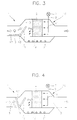
- FIG. 3 illustrates the operating state of the filter trap system when the engine is in the state of low velocity and low load
- FIG. 4 illustrates the operating state of the filter trap system when the engine is in the state of high velocity and high load.
- Controller 5 determines the separating time of the particulate matters by the received signals from back pressure sensor 3 which transmits the pressure difference between the inlet and the outlet, and from engine state sensor 4 which senses the rotating velocity and the load of the engine. At the separating time, controller 5 operates valve driving motor 31 to rotate guiding valve 15 upward.
- compressed air on-off solenoid valve 7 which is installed above the outlet, is opened to supply the compressed air through compressed air supplying line 9.
- the compressed air is supplied through the plurality of compressed air supplying nozzles 11 to metal fiber filter 2 in the opposite direction to the engine exhaust gases to separate the particulate matters from corrugated metal fiber filter 2. Since the compressed air is supplied in the opposite direction to the exhaust gases, the particulate matters fall toward the inlet of filter trap system 1, as illustrated in FIG. 3.
- the separated particulate matters are guided by upward opened guiding valve 15 and collected in collecting box 19.
- Controller 5 determines the separating time of the particulate matters from metal fiber filter 2 by the information signals from back pressure sensor 3 and engine state sensing sensor 4. Then, controller 5 also supplies the electric power to valve driving motor 13 to operate guiding valve 15 and opens compressed air on-off solenoid valve 7 to separate the particulate matters in the case when the engine is in the state of low velocity and low load.
- valve driving motor 13 lets by-pass valve 17 rotate upward with valve driving motor 13 as the axis to prevent the inflow of the engine exhaust gases of high velocity into metal fiber filter 2. Accordingly, the inlet of the engine exhaust gases is cut-off and the external exhausting passageway formed at the inlet portion of filter trap system 1, is opened to exhaust out the engine exhaust gases directly to the outside without the filtering operation.
- the filter trap system according to the first embodiment can control the operations of the by-pass valve and the guiding valve according to the rotating velocity and the load of the engine. Therefore, the amount of the engine exhaust gases exhausted out to the outside without passing the metal fiber filter can be minimized.
- a filter trap system according to another embodiment of the present invention will be explained in detail with reference to FIG. 5.
- the filter trap system illustrated in FIG. 5 is a dual type apparatus which can be obtained by connecting two filter trap systems having almost the same constitutions with the filter trap system according to the first embodiment.
- the constitution of the filter trap system according to the second embodiment is as follows.
- a dual filter trap system 30 includes a first and a second filter trap systems 31a and 31b.
- Dual filter trap system 30 has a first and a second corrugated metal fiber filters 32a and 32b for collecting the particulate matters, a first and a second back pressure sensors 33a and 33b for sensing the pressure differences between the inlets and the outlets of the exhaust gases in first and second filter trap systems 31a and 31b, a controller 35 for receiving information from first and second back pressure sensors 33a and 33b and for controlling various operations, a first and a second compressed air supplying portions 40a and 40b including a first and a second compressed air on-off solenoid valves 37a and 37b, a first and a second compressed air supplying lines 39a and 39b and a first and a second plurality of compressed air supplying nozzles 41a and 41b, for supplying compressed air to first and second corrugated metal fiber filters 32a and 32b, a first and a second particulate matters collecting boxes 49a and 49b for collecting the accumulated
- first filter trap system 31a When the engine (not shown) starts to operate, the engine exhaust gases flow from the engine into dual filter trap system 30.
- the exhaust gases flow into the inlets of first filter trap system 31a and second filter trap system 31b in alternative manner, and the exhaust gases are filtered in each filter trap system as follows.
- first corrugated metal fiber filters 32a When the exhaust gases pass through first corrugated metal fiber filters 32a, the particulate matters included in the exhaust gases are collected at the filters 32a in the same manner as that described in the first embodiment.
- guiding valves 45b upwardly pivots so as to close the inlet thereof and to separate and remove the particulate matters collected at filter 31b.
- first back pressure sensors 33a senses the pressure and transmits the pressure difference to controller 35.
- Controller 35 determines the separating time of the particulate matters by the transmitted signal. At the separating time of the particulate matters, controller 35 supplies the electric power to valve driving motor 43a to operate valve driving motor 43a. Valve driving motor 43a rotates guiding valve 45a upward to open particulate matters collecting box 49a. At the same time, compressed air supplying portion 40a inject the compressed air according to the information signal of controller 35 to separate the particulate matters.
- guiding valve 45a When guiding valve 45a upwardly pivots so as to close the inlet portion thereof, guiding valve 45b of second filter trap system 31b downwardly pivots so as to open the inlet portion thereof and to capture the particulate matters by means of filter 32b. That is, guiding valves 45a and 45b are alternatively operated, thereby allowing the exhaust gases to alternatively flow therethrough.
- each constituting element in each filter trap system 31a and 31b operates by the same method as that described in the first embodiment to collect, separate and remove the particulate matters from the engine exhaust gases.
- the by-pass valve since the controlling of the flowing velocity of the exhaust gases by means of the by-pass valve is not needed, the by-pass valve is not needed as in the first embodiment.
- the problem on the exhaustion of the exhaust gases to the outside without filtering can be solved.
- the engine state sensing sensor for sensing the rotating velocity and the load of the engine and for transmitting this information to the controller, is not needed.
- this sensor can be installed for sensing the engine state.
- the life of the filter trap system can be extended. Moreover, since the supplying of the electric power for burning the collected particulate matters is controlled by the controller, the supplying of the electric power can be adjusted so that no excessive stress is applied to the engine.
- the structure of the filter trap system is relatively simple, the controlling of the apparatus is advantageous and the assembling productivity of the apparatus is increased.
Landscapes
- Engineering & Computer Science (AREA)
- Chemical & Material Sciences (AREA)
- Combustion & Propulsion (AREA)
- Mechanical Engineering (AREA)
- General Engineering & Computer Science (AREA)
- Processes For Solid Components From Exhaust (AREA)
- Filtering Of Dispersed Particles In Gases (AREA)
Description
- The present invention relates to a filtering apparatus for filtering particulate matters (PM) which are exhausted from engine exhaust fumes from automobiles utilizing gasoline, and more particularly, to a counterflow type particulate matter trap system which has a metal fiber filter, collects the particulate matters by means of the fiber filter and removes the captured particulate matters by a counterflow air.
- Generally, the particulate matters mean incomplete combustion matters such as dust generated from an internal combustion engine. Particularly, a large amount of particulate matters are generated from the engine using the gasoline. Accordingly, at the exhaust line of the diesel engine, a filtering apparatus is installed for removing the particulate matters. However, the filtering apparatus is very expensive and improvement on its durability and efficiency is needed. Moreover, the regenerating method which is the core technology of the filtering apparatus is complicated and the controlling thereof is difficult.
- A prior art document, US-A-5253476 discloses a counterflow type particulate matter filter trap system having a controller for receiving and sending information signals; a filter for capturing particulate matter included in engine exhaust gases; a back pressure sensor for sensing a pressure difference between an inlet and an outlet of said filter and for transmitting a signal on said pressure difference to said controller; a compressed air supplying portion which operates by a signal from said controller which outputs an information signal according to said signal received from said back pressure sensor, for injecting compressed air in an opposite direction to a flow of said exhaust gases to separate said captured particulate matter from said filter; a collecting box for collecting said particulate matter separated from said filter; a guiding valve for guiding said particulate matter separated from said filter into said collecting box according to an information signal sent from said controller; and an electric burner provided in said collecting box for burning said particulate matter collected by said filter. The device operates at very high compressed air pressures, and uses high volume flows of compressed air. It is not believed to be suitable for automotive use for vehicles using gasoline.
- Another prior art document, EP-A-0674098 discloses a counterflow type particulate matter filter trap system with two parallel devices used alternately.
- According to the invention there is provided a counterflow particulate matter filter trap system comprising: a controller for receiving and sending information signals; a corrugated fibre filter for capturing particulate matter included in engine exhaust gases; a back pressure sensor for sensing a pressure difference between an inlet and an outlet of said corrugated fibre filter and for transmitting a signal on said pressure difference to said controller; a compressed air supplying portion including a compressed air on-off solenoid valve which is opened and closed by the controller, installed at an outer portion of said filter trap system which operates by a signal from said controller which outputs an information signal according to said signal received from said back pressure sensor, for injecting compressed air in an opposite direction to a flow of said exhaust gases to separate said captured particulate matter from said corrugated fibre filter; a particulate matter collecting box for collecting said particulate matter separated from said corrugated fibre filter; and a guiding valve which is opened and closed by said controller for guiding said particulate matter separated from said corrugated fibre filter into said particulate matter collecting box according to an information signal sent from said controller; characterised by: said corrugated fibre filter being a corrugated metal fibre filter; and said compressed air supplying portion comprises a compressed air supplying line which passes through said filter trap system from an outer portion to an inner portion of said filter trap system and connected to said compressed air on-off solenoid valve, said compressed air supplying line comprises a plurality of compressed air supplying nozzles protruded toward said corrugated metal fibre filter, for injecting said compressed air introduced from said compressed air supplying line to said corrugated metal fibre filter.
- Preferably at least one electric heater is provided in said particulate matter collecting box for burning said collected particulate matter by said filter.
- Conveniently said guiding valve rotates and rises by a predetermined degree to open an inlet of said particulate matter collecting box and guide said particulate matter into said particulate matter collecting box.
Advantageously, the system further comprises a sensor for sensing engine operating conditions to provide information to said controller, and a by-pass valve for controlling a passageway of said exhaust gases according to a signal from said controller. - Conveniently said controller has means for operating said by-pass valve to cut off a flow of said exhaust gases to said filter and to form a separate exhaust passageway to an outer portion of said filter trap system, said controller receiving information from said sensor for sensing an engine operating condition when an engine velocity is higher than a predetermined velocity and when an engine load is larger than a predetermined load.
- In a second embodiment the system has a second corrugated metal fibre filter for capturing particulate matter in engine exhaust gases; a second back pressure sensor for sensing pressure differences between inlets and outlets of said second corrugated metal fibre filter and for transmitting signals on said pressure difference to said controller; a second compressed air supplying portion installed at an outer portion of said filter trap system operated by signals from said controller which outputs information signals according to signals received from said first and said second back pressure sensors, for injecting compressed air in opposite directions to flows of said exhaust gases to separate said captured particulate matter at said second corrugated metal fibre filter, said second compressed air supplying portion including a second compressed air on-off solenoid valve which is opened and closed by said controller, second compressed air supplying lines which pass through said filter trap system from an outer portion to an inner portion of said filter trap system and connected to said second compressed air on-off solenoid valve, said second compressed air supplying lines comprising a plurality of second compressed air supplying nozzles, protruded towards said second corrugated metal fibre filter for respectively injecting said compressed air introduced from said second compressed air supplying lines to said second corrugated metal fibre filter; a second particulate matter collecting box for collecting said particulate matter separated from said second corrugated metal fibre filter; and a second guiding valve which is opened and closed by the controller for guiding said particulate matter separated from said second corrugated metal fibre filter according to information signals sent from said controller.
- Advantageously said first and said second guiding valves rotate and rise by predetermined degrees to open inlets of said first and said particulate collecting boxes and guide said particulate matter into said first and said second particulate matter collecting boxes.
- Conveniently, when one of the inlets of said first and said second particulate matter collecting boxes is opened by one of said first and said second guiding valves, the other of said first and second guiding valve closes an inlet of its corresponding particulate matter collecting box.
- The above object and advantages of the present invention will become more apparent by describing in detail preferred embodiments thereof with reference to the attached drawings in which:
- FIG. 1 is a cross-sectional view of a counterflow type particulate matter filter trap system according to an embodiment of the present invention;
- FIG. 2 is a block diagram for showing the flow of the electric signals of the filter trap system illustrated in FIG. 1 ;
- FIG. 3 is a cross-sectional view for showing the operating state of the filter trap system illustrated in FIG. 1 when an engine is in a state of low velocity and low load;
- FIG. 4 is a cross-sectional view for showing the operating state of the filter trap system illustrated in FIG. 1 when an engine is in a state of high velocity and high load; and
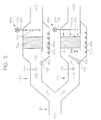
- FIG. 5 is a cross-sectional view of a counterflow type particulate matter filter trap system according to another embodiment of the present invention.
-
- Hereinafter, the filter trap system according to an embodiment of the present invention will be explained in more detail with reference to the accompanying drawings.
- FIG. 1 is a cross-sectional view of a counterflow type particulate matter filter trap system according to an embodiment of the present invention, and FIG. 2 is a block diagram for showing the flow of the electric signals of the filter trap system.
- Referring to FIG. 1, a particulate matter
filter trap system 1 according to this embodiment of the present invention includes a metal fiber filter, preferably a corrugatedmetal fiber filter 2 for capturing the particulate matters, aback pressure sensor 3 for sensing a gas pressure difference infilter trap system 1, acontroller 5 for receiving information fromback pressure sensor 3 and an engine operatingcondition sensing sensor 4 and for controlling various operations, a compressedair supplying portion 10 which includes a compressed air on-off solenoid valve 7, for supplying a compressed air to corrugatedmetal fiber filter 2, a compressed air supplying line 9 and a plurality of compressed air supplying nozzles 11, a particulatematters collecting box 19 for collecting the accumulated particulate matters, a guidingvalve 15 for opening and closing the upper portion of particulatematters collecting box 19, a by-pass valve for opening and closing the inlet offilter trap system 1, a drivingmotor 13 for driving by-pass valve 17, and anelectric heater 21 for burning the collected particulate matters in collectingbox 19. - At one portion of
filter trap system 1, an inlet for sucking exhaust gases from an engine (not shown) is provided, and an outlet for exhausting the sucked gas is provided at the other portion thereof. At the center portion of the body offilter trap system 1, corrugatedmetal fiber filter 2 is installed, and particulatematters collecting box 19 is formed at the lower portion of the body offilter trap system 1.Electric heater 19 is disposed at the inner and lower surface portion of particulatematters collecting box 19. Valve drivingmotor 13 is installed at the contacting portion of particulatematters collecting box 19 with the inlet. - At one portion of
valve driving motor 13 and above particulatematters collecting box 19, guidingvalve 15 is formed for opening and closing one upper portion of particulatematters collecting box 19. At the other portion ofvalve driving motor 13, by-pass valve 17 is installed for opening and closing the inlet offilter trap system 1. And between corrugatedmetal fiber filter 2 and the outlet of the filter trap system, compressed air supplying line 9 is vertically extended from the outer portion of the body to the lower portion of corrugatedmetal fiber filter 2. At one end of compressed air supplying line 9, a plurality of compressed air supplying nozzles are protrusively formed to a fixed distance toward corrugatedmetal fiber filter 2. At the upper end portion of compressed air supplying line 9, compressed air on-off solenoid valve 7 is installed. -
Back pressure sensor 3 is installed at the center portion where the inlet and the body are connected.Controller 5 is separately formed fromfilter trap system 1. - The operation of
controller 5 will be explained with reference to the block diagram in FIG. 2 and FIG. 1. First,back pressure sensor 3 senses the gas pressure at the inlet before the gas passesmetal fiber filter 2, and transmits this information to controller 5. In addition, engine operatingcondition sensing sensor 4 senses the rotating velocity and the load of the engine and transmits this information to controller 5.Controller 5 receives the two kinds of information, judges the accumulated degree of the particulate matters from the information fromback pressure sensor 3 and determines the engine operating condition from the information from enginestate sensing sensor 4. Whencontroller 5 judges that an appropriate amount of particulate matters is accumulated through the information fromback pressure sensor 3, the controller opens compressed air on-off solenoid valve 7 to inject the compressed air through compressed air supplying line 9 and the plurality of compressed air supplying nozzles 11 in the opposite direction to the exhaust gases. In addition,controller 5 judges the flowing velocity of the exhaust gases according to the engine operating condition to determine if it opens by-pass valve 17 or not and transmits the judgement to drivingmotor 13. - The operating principle of the filter trap system and the method for filtering the exhaust gases according to this embodiment will be described in detail below.
- When the engine (not shown) starts to operate, the engine exhaust gases flow from the engine into
filter trap system 1. The arrows illustrated in FIG. 1 represent the flowing direction of the engine exhaust gases from the engine. - When the exhaust gases move along the direction indicated by the arrows from the inlet and pass through corrugated
metal fiber filter 2 which is disposed at the center portion, the particulate matters included in the exhaust gases is captured byfilter 2. As the particulate matters are accumulated, a difference between the pressure at the inlet portion offilter trap system 1 and the pressure at the outlet portion afterfilter 2, is generated. As time goes by, the amount of the particulate matters increases and the pressure difference becomes larger.Back pressure sensor 3 installed at the inlet portion offilter trap system 1 senses the two pressure difference and transmits the pressure difference tocontroller 5. Meanwhile, engine operatingcondition sensing sensor 4 installed at a predetermined position, senses the rotating speed and the load of the engine to transmit this information to controller 5. -
Controller 5 receives signals fromback pressure sensor 3 which transmits the pressure difference between the inlet and the outlet of the filter trap system and from enginestate sensing sensor 4 which senses the rotating velocity and the load of the engine, and determines the separating time of the particulate matters. When the separating time of the particulate matters is determined,controller 5 supplies an electric power tovalve driving motor 13 which is installed at the inlet portion offilter trap system 1 to drivevalve driving motor 13. Valve drivingmotor 13 lets guiding valve which is horizontally provided at one side of drivingmotor 13, rotate upward with drivingmotor 13 as the axis, to open particulatematters collecting box 19 which is provided at the lower portion offilter trap system 1. - At the same time, compressed air on-off solenoid valve 7 installed above the outlet of
filter trap system 1, is opened to supply the compressed air through compressed air supplying line 9 which is vertically extended from compressed air on-off solenoid valve 7 to the inner portion offilter trap system 1. Compressed air supplying line 9 includes a plurality of compressed air supplying nozzles 11 which is protruded towardmetal fiber filter 2 offilter trap system 1. Accordingly, the supplied compressed air is transmitted to the plurality of compressed air supplying nozzles 11 from compressed air supplying line 9. The compressed air is injected from the plurality of compressed air supplying nozzles 11 intometal fiber filter 2 in the opposite direction to the engine exhaust gases, to separate the particulate matters from corrugatedmetal fiber filter 2. At this time, since the plurality of compressed air supplying nozzles 11 supplies the compressed air in the opposite direction to the engine exhaust gases to corrugatedmetal fiber filter 2, the particulate matters overcome the pressure of the exhaust gases and falls toward the inlet portion offilter trap system 1. - The separated particulate matters from
metal fiber filter 2 is guided by rotated guidingvalve 15 and is collected at the openedcollecting box 19. After completing the collection of the particulate matters, drivingmotor 13 operates guidingvalve 13 to shutcollecting box 19, and the exhaust gases continuously pass throughmetal fiber filter 2.Electric heater 21 is provided in particulatematters collecting box 19. The electric power is supplied toelectric heater 21 by the signal fromcontroller 5 and the collected particulate matters are fired byheater 21. At this time, the amount of the supplied electric power toelectric heater 21 should be controlled so as not to excessively affect the engine operation. - The filter trap system according to this embodiment controls the by-pass valve to minimize the by-pass ratio of the exhaust gases according to the engine state The engine state can be classified into a low velocity and low load state and a high velocity and high load state. FIG. 3 illustrates the operating state of the filter trap system when the engine is in the state of low velocity and low load and FIG. 4 illustrates the operating state of the filter trap system when the engine is in the state of high velocity and high load. These will be compared, hereinafter. In FIGs. 3 & 4, the same reference numerals are given to the same parts.
- First, the operation of the filter trap system when the engine is in the state of low velocity and the low load, will be explained with reference to FIG. 3.
Controller 5 determines the separating time of the particulate matters by the received signals fromback pressure sensor 3 which transmits the pressure difference between the inlet and the outlet, and fromengine state sensor 4 which senses the rotating velocity and the load of the engine. At the separating time,controller 5 operates valve driving motor 31 to rotate guidingvalve 15 upward. - When particulate
matters collecting box 19 is opened, compressed air on-off solenoid valve 7 which is installed above the outlet, is opened to supply the compressed air through compressed air supplying line 9. The compressed air is supplied through the plurality of compressed air supplying nozzles 11 tometal fiber filter 2 in the opposite direction to the engine exhaust gases to separate the particulate matters from corrugatedmetal fiber filter 2. Since the compressed air is supplied in the opposite direction to the exhaust gases, the particulate matters fall toward the inlet offilter trap system 1, as illustrated in FIG. 3. The separated particulate matters are guided by upward opened guidingvalve 15 and collected in collectingbox 19. - Since the flowing velocity of the exhaust gases is weak, almost all of the particulate matters can be collected without being affected by the continuous inflow of the exhaust gases. When guiding
valve 15 operates downward to close the collecting box, the particulate matters are fired byelectric heater 21. - The operating state of the filter trap system when the engine is in the state of high velocity and high load. will be explained with reference to FIG. 4.
- The particulate matters included in the exhaust gases are accumulated when the gas passes through corrugated
metal fiber filter 2 and when the engine is in the state of high velocity and high load, as illustrated in FIG. 3.Controller 5 determines the separating time of the particulate matters frommetal fiber filter 2 by the information signals fromback pressure sensor 3 and enginestate sensing sensor 4. Then,controller 5 also supplies the electric power tovalve driving motor 13 to operate guidingvalve 15 and opens compressed air on-off solenoid valve 7 to separate the particulate matters in the case when the engine is in the state of low velocity and low load. - In addition,
valve driving motor 13 lets by-pass valve 17 rotate upward withvalve driving motor 13 as the axis to prevent the inflow of the engine exhaust gases of high velocity intometal fiber filter 2. Accordingly, the inlet of the engine exhaust gases is cut-off and the external exhausting passageway formed at the inlet portion offilter trap system 1, is opened to exhaust out the engine exhaust gases directly to the outside without the filtering operation. - When guiding
valve 15 rotates upward to open particulatematters collecting box 19. the compressed air is injected intometal fiber filter 2 through compressed air on-off solenoid valve 7, compressed air supplying line 9 and compressed air supplying nozzle 11, in the opposite direction to the engine exhaust gases. The separated particulate matters frommetal fiber filter 2 are guided by guidingvalve 15 and collected in opened particulatematters collecting box 19. At this time, since the inflow of the engine exhaust gases of high velocity is cut-off, the particulate matters can be safely separated and collected in the collecting box. After completing the collection, by-pass valve 17 and guidingvalve 15 go back to their original positions and the engine exhaust gases pass again throughmetal fiber filter 2. The collected particulate matters are burned byelectric heater 21 in collectingbox 19. - As described above, the filter trap system according to the first embodiment can control the operations of the by-pass valve and the guiding valve according to the rotating velocity and the load of the engine. Therefore, the amount of the engine exhaust gases exhausted out to the outside without passing the metal fiber filter can be minimized.
- A filter trap system according to another embodiment of the present invention will be explained in detail with reference to FIG. 5.
- The filter trap system illustrated in FIG. 5 is a dual type apparatus which can be obtained by connecting two filter trap systems having almost the same constitutions with the filter trap system according to the first embodiment. The constitution of the filter trap system according to the second embodiment is as follows.
- A dual
filter trap system 30 according to this embodiment includes a first and a secondfilter trap systems 31a and 31b. Dual filter trap system 30 has a first and a second corrugated metal fiber filters 32a and 32b for collecting the particulate matters, a first and a second back pressure sensors 33a and 33b for sensing the pressure differences between the inlets and the outlets of the exhaust gases in first and second filter trap systems 31a and 31b, a controller 35 for receiving information from first and second back pressure sensors 33a and 33b and for controlling various operations, a first and a second compressed air supplying portions 40a and 40b including a first and a second compressed air on-off solenoid valves 37a and 37b, a first and a second compressed air supplying lines 39a and 39b and a first and a second plurality of compressed air supplying nozzles 41a and 41b, for supplying compressed air to first and second corrugated metal fiber filters 32a and 32b, a first and a second particulate matters collecting boxes 49a and 49b for collecting the accumulated particulate matters, a first and a second guiding valves 45a and 45b for opening and closing the upper portions of first and second particulate matters collecting boxes 49a and 49b, a first and a second driving motors 43a and 43b for driving first and second guiding valves 45a and 45b, and a first and a second electric heaters 51a and 51b for burning the collected particulate matters collected in first and second collecting boxes 49a and 49b. - The basic role and the basic operating principle of each part and the method for filtering the exhaust gases using the dual filter trap system are almost exactly the same as those explained in the first embodiment. Accordingly, the same content will be omitted and the different portion will be briefly explained below.
- When the engine (not shown) starts to operate, the engine exhaust gases flow from the engine into dual
filter trap system 30. The exhaust gases flow into the inlets of firstfilter trap system 31a and second filter trap system 31b in alternative manner, and the exhaust gases are filtered in each filter trap system as follows. When the exhaust gases pass through first corrugatedmetal fiber filters 32a, the particulate matters included in the exhaust gases are collected at thefilters 32a in the same manner as that described in the first embodiment. At this time, in second filter trap system 31b, guiding valves 45b upwardly pivots so as to close the inlet thereof and to separate and remove the particulate matters collected at filter 31b. Meanwhile, as the amount of the accumulated particulate matters atfilter 31a increases, the pressure difference between the pressures at the inlet portion and the pressure at the outlet portion thereof become larger. Accordingly, firstback pressure sensors 33a senses the pressure and transmits the pressure difference to controller 35. Controller 35 determines the separating time of the particulate matters by the transmitted signal. At the separating time of the particulate matters, controller 35 supplies the electric power tovalve driving motor 43a to operatevalve driving motor 43a.Valve driving motor 43a rotates guidingvalve 45a upward to open particulatematters collecting box 49a. At the same time, compressedair supplying portion 40a inject the compressed air according to the information signal of controller 35 to separate the particulate matters. - When guiding
valve 45a upwardly pivots so as to close the inlet portion thereof, guiding valve 45b of second filter trap system 31b downwardly pivots so as to open the inlet portion thereof and to capture the particulate matters by means of filter 32b. That is, guidingvalves 45a and 45b are alternatively operated, thereby allowing the exhaust gases to alternatively flow therethrough. - As described above, each constituting element in each
filter trap system 31a and 31b operates by the same method as that described in the first embodiment to collect, separate and remove the particulate matters from the engine exhaust gases. In the above described embodiment, since the controlling of the flowing velocity of the exhaust gases by means of the by-pass valve is not needed, the by-pass valve is not needed as in the first embodiment. In addition, the problem on the exhaustion of the exhaust gases to the outside without filtering can be solved. And therefore, the engine state sensing sensor for sensing the rotating velocity and the load of the engine and for transmitting this information to the controller, is not needed. However, it goes without saying that this sensor can be installed for sensing the engine state. - As described above, since the particulate matters are not directly treated by the filter, the life of the filter trap system can be extended. Moreover, since the supplying of the electric power for burning the collected particulate matters is controlled by the controller, the supplying of the electric power can be adjusted so that no excessive stress is applied to the engine.
- Further, since the structure of the filter trap system is relatively simple, the controlling of the apparatus is advantageous and the assembling productivity of the apparatus is increased.
- Although the preferred embodiment of the invention has been described, it is understood that the present invention should not be limited to the preferred embodiment, but various changes and modifications can be made by one skilled in the art within the scope of the invention as hereinafter claimed.
Claims (8)
- A counterflow particulate matter filter trap system comprising:characterised by:a controller (5) for receiving and sending information signals;a corrugated fibre filter (2) for capturing particulate matter included in engine exhaust gases;a back pressure sensor (3) for sensing a pressure difference between an inlet and an outlet of said corrugated fibre filter and for transmitting a signal on said pressure difference to said controller (5) ;a compressed air supplying portion (10) including a compressed air on-off solenoid valve (7) which is opened and closed by the controller (5), installed at an outer portion of said filter trap system which operates by a signal from said controller which outputs an information signal according to said signal received from said back pressure sensor (3), for injecting compressed air in an opposite direction to a flow of said exhaust gases to separate said captured particulate matter from said corrugated fibre filter (2) ;a particulate matter collecting box (19) for collecting said particulate matter separated from said corrugated fibre filter (2); anda guiding valve (15) which is opened and closed by said controller (5) for guiding said particulate matter separated from said corrugated fibre filter (2) into said particulate matter collecting box (19) according to an information signal sent from said controller (5);said corrugated fibre filter (2) being a corrugated metal fibre filter; andsaid compressed air supplying portion (10) comprises a compressed air supplying line (9) which passes through said filter trap system from an outer portion to an inner portion of said filter trap system and connected to said compressed air on-off solenoid valve (7), said compressed air supplying line (9) comprises a plurality of compressed air supplying nozzles (11) protruded toward said corrugated metal fibre filter (2), for injecting said compressed air introduced from said compressed air supplying line (9) to said corrugated metal fibre filter (2).
- A system as claimed in claim 1, wherein at least one electric heater (21) is provided in said particulate matter collecting box for burning said collected particulate matter by said filter.
- A system as claimed in claim 1, wherein said guiding valve (15) rotates and rises by a predetermined degree to open an inlet of said particulate matter collecting box (19) and guide said particulate matter into said particulate matter collecting box.
- A system as claimed in claim 1, further comprising a sensor (4) for sensing engine operating conditions to provide information to said controller, and a by-pass valve (17) for controlling a passageway of said exhaust gases according to a signal from said controller.
- A system as claimed in claim 4, wherein said controller (5) has means for operating said by-pass valve (17) to cut off a flow of said exhaust gases to said filter and to form a separate exhaust passageway to an outer portion of said filter trap system, said controller (5) receiving information from said sensor (4) for sensing an engine operating condition when an engine velocity is higher than a predetermined velocity and when an engine load is larger than a predetermined load.
- A system comprising the system of claim 1 and further comprising:a second corrugated metal fibre filter (32b) for capturing particulate matter in engine exhaust gases;a second back pressure sensor (33b) for sensing pressure differences between inlets and outlets of said second corrugated metal fibre filter and for transmitting signals on said pressure difference to said controller;a second compressed air supplying portion (40b) installed at an outer portion of said filter trap system operated by signals from said controller (35) which outputs information signals according to signals received from said first and said second back pressure sensors (33a;33b), for injecting compressed air in opposite directions to flows of said exhaust gases to separate said captured particulate matter at said second corrugated metal fibre filter (32b), said second compressed air supplying portion (40b) including a second compressed air on-off solenoid valve which is opened and closed by said controller, second compressed air supplying lines which pass through said filter trap system from an outer portion to an inner portion of said filter trap system and connected to said second compressed air on-off solenoid valve, said second compressed air supplying lines comprising a plurality of second compressed air supplying nozzles (41b), protruded towards said second corrugated metal fibre filter (32b) for respectively injecting said compressed air introduced from said second compressed air supplying lines to said second corrugated metal fibre filter (32b);a second particulate matter collecting box (49b)for collecting said particulate matter separated from said second corrugated metal fibre filter (32b); anda second guiding valve (45b) which is opened and closed by the controller for guiding said particulate matter separated from said second corrugated metal fibre filter according to information signals sent from said controller.
- A system as claimed in claim 6, wherein said first and said second guiding valves (45a,45b)rotate and rise by predetermined degrees to open inlets of said first and said particulate collecting boxes (49a,49b) and guide said particulate matter into said first and said second particulate matter collecting boxes (49a,49b).
- The system as claimed in claim 7, wherein when one of the inlets of said first and said second particulate matter collecting boxes (49a,49b) is opened by one of said first and said second guiding valves (45a,45b), the other of said first and second guiding valve (45b,45a) closes an inlet of its corresponding particulate matter collecting box (49a,49b).
Priority Applications (4)
| Application Number | Priority Date | Filing Date | Title |
|---|---|---|---|
| US09/006,116 US6010547A (en) | 1998-01-13 | 1998-01-13 | Counterflow type particulate matter filter trap system having metal fiber filter |
| EP98300275A EP0930422B1 (en) | 1998-01-13 | 1998-01-15 | Counterflow type particulate matter filter trap system having metal fiber filter |
| DE1998606461 DE69806461T2 (en) | 1998-01-15 | 1998-01-15 | Counterflow particle filter separation system with metal fiber filter |
| JP10012969A JP2957981B2 (en) | 1998-01-13 | 1998-01-26 | Back-flow type particulate matter filtering device having metal fiber filter |
Applications Claiming Priority (3)
| Application Number | Priority Date | Filing Date | Title |
|---|---|---|---|
| US09/006,116 US6010547A (en) | 1998-01-13 | 1998-01-13 | Counterflow type particulate matter filter trap system having metal fiber filter |
| EP98300275A EP0930422B1 (en) | 1998-01-13 | 1998-01-15 | Counterflow type particulate matter filter trap system having metal fiber filter |
| JP10012969A JP2957981B2 (en) | 1998-01-13 | 1998-01-26 | Back-flow type particulate matter filtering device having metal fiber filter |
Publications (2)
| Publication Number | Publication Date |
|---|---|
| EP0930422A1 EP0930422A1 (en) | 1999-07-21 |
| EP0930422B1 true EP0930422B1 (en) | 2002-07-10 |
Family
ID=27239486
Family Applications (1)
| Application Number | Title | Priority Date | Filing Date |
|---|---|---|---|
| EP98300275A Expired - Lifetime EP0930422B1 (en) | 1998-01-13 | 1998-01-15 | Counterflow type particulate matter filter trap system having metal fiber filter |
Country Status (3)
| Country | Link |
|---|---|
| US (1) | US6010547A (en) |
| EP (1) | EP0930422B1 (en) |
| JP (1) | JP2957981B2 (en) |
Cited By (1)
| Publication number | Priority date | Publication date | Assignee | Title |
|---|---|---|---|---|
| US11506099B1 (en) | 2021-08-24 | 2022-11-22 | Tenneco Automotive Operating Company Inc. | Electrically-heated mix pipe for processing diesel exhaust fluid in a selective catalytic reduction system |
Families Citing this family (39)
| Publication number | Priority date | Publication date | Assignee | Title |
|---|---|---|---|---|
| ES2157793B1 (en) * | 1999-05-25 | 2002-02-16 | Franco Eusebio Moro | SMOKE FILTER |
| JP3570297B2 (en) * | 1999-06-10 | 2004-09-29 | 株式会社日立製作所 | Engine exhaust purification device |
| ES2169632B1 (en) * | 1999-09-22 | 2003-11-16 | Franco Eusebio Moro | IMPROVEMENTS INTRODUCED IN FILTERS FOR SMOKE. |
| US6365108B1 (en) * | 1999-10-12 | 2002-04-02 | Caterpillar Inc. | Siloxane filter for O2 sensor for bio-gas engine |
| US6675572B2 (en) | 2000-09-14 | 2004-01-13 | Siemens Automotive Inc. | Valve including a recirculation chamber |
| HUP0302423A3 (en) | 2000-10-31 | 2004-07-28 | Faurecia Sys Echappement | Method for cleaning the upstream surface of a particulate filter |
| US6708104B2 (en) | 2001-07-27 | 2004-03-16 | Detroit Diesel Corporation | Engine control based on exhaust back pressure |
| US6830599B1 (en) | 2001-12-10 | 2004-12-14 | Christy, Inc. | Back-flow valve and trigger for cleaning machine |
| US6651638B1 (en) | 2002-06-28 | 2003-11-25 | Cummins Engine Company, Inc. | System and method for derating an engine to encourage servicing of a vehicle |
| US6948486B2 (en) * | 2002-06-28 | 2005-09-27 | Fleetguard, Inc. | System and method for derating an engine to encourage servicing of a vehicle |
| US7025811B2 (en) * | 2002-08-23 | 2006-04-11 | Cleaire Advanced Emission Controls | Apparatus for cleaning a diesel particulate filter with multiple filtration stages |
| DE10323735A1 (en) * | 2003-05-24 | 2004-12-09 | Daimlerchrysler Ag | Process for cleaning a particulate filter |
| US7992382B2 (en) * | 2003-08-01 | 2011-08-09 | Illinois Valley Holding Company | Particulate trap system and method |
| DE10343045A1 (en) * | 2003-09-16 | 2005-04-07 | Deutz Ag | Method and device for the negative pressure deposition and disposal of particles from fluid streams |
| US7332016B2 (en) * | 2004-07-30 | 2008-02-19 | Caterpillar Inc. | Particulate trap with selective blocking element |
| US7419532B2 (en) * | 2004-10-05 | 2008-09-02 | Caterpillar Inc. | Deposition system and method |
| US7384455B2 (en) * | 2004-10-05 | 2008-06-10 | Caterpillar Inc. | Filter service system and method |
| US20060070360A1 (en) * | 2004-10-05 | 2006-04-06 | Caterpillar Inc. | Filter service system and method |
| US7462222B2 (en) * | 2004-10-05 | 2008-12-09 | Caterpillar Inc. | Filter service system |
| US7410529B2 (en) * | 2004-10-05 | 2008-08-12 | Caterpillar Inc. | Filter service system and method |
| US20060191412A1 (en) * | 2005-02-28 | 2006-08-31 | Caterpillar Inc. | Filter service system and method |
| US7410521B2 (en) * | 2005-02-28 | 2008-08-12 | Caterpillar Inc. | Filter service system and method |
| US7905947B2 (en) * | 2006-05-24 | 2011-03-15 | L.C. Eldridge Sales Co., Ltd. | Method and apparatus for removing contaminates from air |
| US7716922B2 (en) * | 2006-10-20 | 2010-05-18 | International Truck Intellectual Property Company, Llc | Diesel particulate filter (DPF) in-chassis cleaning method |
| US20090000479A1 (en) | 2007-06-28 | 2009-01-01 | Cleaire Advanced Emission Controls, Llc | Apparatus and method for delivering a fluid to a diesel particulate filter |
| US8142552B2 (en) * | 2007-06-29 | 2012-03-27 | Caterpillar Inc. | Filter purge system utilizing a reactive propellant |
| US8157897B2 (en) * | 2007-06-29 | 2012-04-17 | Caterpillar Inc. | Filter purge system utilizing impact wave generating device and vacuum source |
| US8516654B1 (en) | 2009-10-05 | 2013-08-27 | Pathfinder Concepts, Llc | Filter system for a vacuum cleaner |
| CN104454084B (en) * | 2014-09-03 | 2017-11-28 | 内蒙古农业大学职业技术学院 | A kind of pulse cleaning eddy flow trap |
| CN105569781B (en) * | 2015-12-03 | 2017-12-01 | 武汉华威专用汽车检测有限责任公司 | A kind of vehicle-mounted ashes of diesel engine particle catcher remove system and its control method |
| CN106014575A (en) * | 2016-07-25 | 2016-10-12 | 无锡市永亿精密铸造有限公司 | Automobile tail gas purification device |
| US10167763B2 (en) * | 2016-08-30 | 2019-01-01 | Ford Global Technologies, Llc | Fluid flow adjustment door with pivotable inner door |
| KR102135327B1 (en) * | 2018-07-26 | 2020-07-20 | 한국기계연구원 | Single particle dispensing apparatus and single particle dispensing method using the same |
| EP3636889A1 (en) * | 2018-10-10 | 2020-04-15 | Ceramex Ltd | Method for cleaning and/or testing a gas-permeable device for cleaning an exhaust gas of a combustion engine and apparatus suitable for same |
| US11339750B2 (en) | 2020-04-29 | 2022-05-24 | Deere & Company | Combustion air filtration apparatus |
| EP3957836B1 (en) * | 2020-08-21 | 2024-01-10 | Volvo Truck Corporation | A method for cleaning a component of an exhaust aftertreatment system and an exhaust system |
| KR102564861B1 (en) * | 2021-05-11 | 2023-08-10 | 주식회사 해림엔지니어링 | Combined thermal power heat recovery boiler dust collector |
| EP4711082A2 (en) * | 2022-07-07 | 2026-03-18 | Husqvarna AB | Pre-filter arrangements and valves for an industrial dust extractor |
| KR102932398B1 (en) | 2023-03-10 | 2026-02-27 | 주식회사 해림엔지니어링 | Combined thermal power heat recovery boiler Electrostatic dust collector |
Family Cites Families (22)
| Publication number | Priority date | Publication date | Assignee | Title |
|---|---|---|---|---|
| DE3148721A1 (en) * | 1981-12-09 | 1983-07-21 | Heinz 4006 Erkrath Ludewig | Method and device for lowering the exposure to exhaust gas when motor vehicles and internal combustion engines are operated and used |
| FR2538448A1 (en) * | 1982-12-28 | 1984-06-29 | Peugeot | DEVICE FOR CONTROLLING THE PROCESS OF REGENERATING A PARTICLE FILTER PLACED ON THE EXHAUST OF A COMPRESSION-IGNITION ENGINE |
| US4512147A (en) * | 1983-01-07 | 1985-04-23 | Cummins Engine Company, Inc. | Method and apparatus for removing carbon particles from engine exhausts |
| JPS59153914A (en) * | 1983-02-21 | 1984-09-01 | Nissan Motor Co Ltd | Regenerative burner control device in exhaust particle trap in internal-combustion engine |
| EP0213725A3 (en) * | 1985-08-05 | 1987-07-29 | BREHK Ventures | Method and apparatus for trapping and incinerating particulate matter found in diesel engine exhaust |
| DE3717140A1 (en) * | 1987-05-21 | 1988-12-08 | Webasto Ag Fahrzeugtechnik | Soot filter system in the exhaust tract of a diesel internal combustion engine |
| DE3788421T2 (en) * | 1987-09-22 | 1994-06-30 | Asahi Glass Co Ltd | Apparatus for treating particles in the exhaust gas from a diesel engine. |
| JPH0823288B2 (en) * | 1988-09-08 | 1996-03-06 | 旭硝子株式会社 | Particulate trap device |
| JPH03202609A (en) * | 1989-12-28 | 1991-09-04 | Nissan Motor Co Ltd | Engine exhaust emission control device |
| JPH0661419B2 (en) * | 1991-02-21 | 1994-08-17 | 日本碍子株式会社 | Exhaust gas treatment device |
| DE4134949C2 (en) * | 1991-10-23 | 1993-12-16 | Daimler Benz Ag | Device for maintenance and regeneration of a soot filter |
| US5253476A (en) * | 1992-02-21 | 1993-10-19 | Northeastern University | Pulsed, reverse-flow, regenerated diesel trap capturing soot, ash and PAH's |
| US5390492A (en) * | 1992-02-21 | 1995-02-21 | Northeastern University | Flow-through particulate incineration system coupled to an aerodynamically regenerated particulate trap for diesel engine exhaust gas |
| US5426936A (en) * | 1992-02-21 | 1995-06-27 | Northeastern University | Diesel engine exhaust gas recirculation system for NOx control incorporating a compressed air regenerative particulate control system |
| JP2894103B2 (en) * | 1992-09-09 | 1999-05-24 | 松下電器産業株式会社 | Exhaust gas purification device |
| JP2957865B2 (en) * | 1993-10-27 | 1999-10-06 | 日野自動車工業株式会社 | Backwashing particulate collection equipment |
| JP2839851B2 (en) * | 1994-03-23 | 1998-12-16 | 日本碍子株式会社 | Exhaust gas treatment method and apparatus |
| JPH07332064A (en) * | 1994-06-10 | 1995-12-19 | Ngk Insulators Ltd | Exhaust gas filter and exhaust gas processing equipment |
| JP3288536B2 (en) * | 1994-06-21 | 2002-06-04 | 日本碍子株式会社 | Exhaust gas filter and exhaust gas treatment device using the same |
| EP0764455B1 (en) * | 1995-09-25 | 2002-11-20 | Sintokogio, Ltd. | A filter for a treatment of carbon-based particles in exhaust gas and a device for said treatment using said filter |
| JPH09112248A (en) * | 1995-10-16 | 1997-04-28 | Hino Motors Ltd | Back wash reconditioning device for diesel particulate filter |
| JPH09217618A (en) * | 1996-02-09 | 1997-08-19 | Isuzu Ceramics Kenkyusho:Kk | Exhaust gas purification device |
-
1998
- 1998-01-13 US US09/006,116 patent/US6010547A/en not_active Expired - Fee Related
- 1998-01-15 EP EP98300275A patent/EP0930422B1/en not_active Expired - Lifetime
- 1998-01-26 JP JP10012969A patent/JP2957981B2/en not_active Expired - Fee Related
Cited By (1)
| Publication number | Priority date | Publication date | Assignee | Title |
|---|---|---|---|---|
| US11506099B1 (en) | 2021-08-24 | 2022-11-22 | Tenneco Automotive Operating Company Inc. | Electrically-heated mix pipe for processing diesel exhaust fluid in a selective catalytic reduction system |
Also Published As
| Publication number | Publication date |
|---|---|
| JP2957981B2 (en) | 1999-10-06 |
| EP0930422A1 (en) | 1999-07-21 |
| US6010547A (en) | 2000-01-04 |
| JPH11207121A (en) | 1999-08-03 |
Similar Documents
| Publication | Publication Date | Title |
|---|---|---|
| US6010547A (en) | Counterflow type particulate matter filter trap system having metal fiber filter | |
| US5426936A (en) | Diesel engine exhaust gas recirculation system for NOx control incorporating a compressed air regenerative particulate control system | |
| EP0816646B1 (en) | Reverse cleaning regeneration type exhaust emission control device and method of regenerating the same | |
| US8252093B2 (en) | Filter service system and method | |
| US8256060B2 (en) | Apparatus for cleaning exhaust aftertreatment devices and methods | |
| CA2183537C (en) | A flow-through particulate incineration system coupled to an aerodynamically regenerated particulate trap for diesel engine exhaust gas | |
| US20060191412A1 (en) | Filter service system and method | |
| JPS6179814A (en) | Fine particle exhaust disposing device for internal combustion engine | |
| JPH0627501B2 (en) | Exhaust particulate removal device for diesel engine | |
| JP3713923B2 (en) | Diesel particulate filter regeneration device | |
| KR19980026228A (en) | Counterflow particulate filter with metal fiber filter | |
| JP3112144B2 (en) | Dust collector soot treatment device | |
| JPH0631121A (en) | Honeycomb filter | |
| JPH02115014A (en) | Dust collecting apparatus | |
| JPH07197805A (en) | Exhaust particulate removal device | |
| JPH01240713A (en) | Exhaust micro-particle purifying device for diesel engine | |
| KR100588535B1 (en) | Water removal method of vehicle exhaust gas particulate matter removal device | |
| CA1260407A (en) | Regenerative filter trap system with apparatus for diverting the exhaust gas flow | |
| JP3674099B2 (en) | Filter regeneration device for internal combustion engine | |
| JP2842279B2 (en) | Filter regeneration device for internal combustion engine | |
| JPH03222808A (en) | Exhaust gas particulate cleaning device for internal combustion engine | |
| JPH0281914A (en) | Filter washing device | |
| JPH05156923A (en) | Backwasher of particulate filter | |
| JPH07301112A (en) | Exhaust smoke removing device for engine | |
| JPH08158856A (en) | Filter cleaning device |
Legal Events
| Date | Code | Title | Description |
|---|---|---|---|
| PUAI | Public reference made under article 153(3) epc to a published international application that has entered the european phase |
Free format text: ORIGINAL CODE: 0009012 |
|
| AK | Designated contracting states |
Kind code of ref document: A1 Designated state(s): DE FR GB GR IT |
|
| AX | Request for extension of the european patent |
Free format text: AL;LT;LV;MK;RO;SI |
|
| 17P | Request for examination filed |
Effective date: 19991223 |
|
| AKX | Designation fees paid |
Free format text: DE FR GB GR IT |
|
| 17Q | First examination report despatched |
Effective date: 20001020 |
|
| GRAG | Despatch of communication of intention to grant |
Free format text: ORIGINAL CODE: EPIDOS AGRA |
|
| GRAG | Despatch of communication of intention to grant |
Free format text: ORIGINAL CODE: EPIDOS AGRA |
|
| GRAH | Despatch of communication of intention to grant a patent |
Free format text: ORIGINAL CODE: EPIDOS IGRA |
|
| GRAH | Despatch of communication of intention to grant a patent |
Free format text: ORIGINAL CODE: EPIDOS IGRA |
|
| GRAA | (expected) grant |
Free format text: ORIGINAL CODE: 0009210 |
|
| AK | Designated contracting states |
Kind code of ref document: B1 Designated state(s): DE FR GB GR IT |
|
| PG25 | Lapsed in a contracting state [announced via postgrant information from national office to epo] |
Ref country code: IT Free format text: LAPSE BECAUSE OF FAILURE TO SUBMIT A TRANSLATION OF THE DESCRIPTION OR TO PAY THE FEE WITHIN THE PRESCRIBED TIME-LIMIT;WARNING: LAPSES OF ITALIAN PATENTS WITH EFFECTIVE DATE BEFORE 2007 MAY HAVE OCCURRED AT ANY TIME BEFORE 2007. THE CORRECT EFFECTIVE DATE MAY BE DIFFERENT FROM THE ONE RECORDED. Effective date: 20020710 Ref country code: GR Free format text: LAPSE BECAUSE OF FAILURE TO SUBMIT A TRANSLATION OF THE DESCRIPTION OR TO PAY THE FEE WITHIN THE PRESCRIBED TIME-LIMIT Effective date: 20020710 Ref country code: FR Free format text: LAPSE BECAUSE OF NON-PAYMENT OF DUE FEES Effective date: 20020710 |
|
| REG | Reference to a national code |
Ref country code: GB Ref legal event code: FG4D |
|
| REF | Corresponds to: |
Ref document number: 69806461 Country of ref document: DE Date of ref document: 20020814 |
|
| PG25 | Lapsed in a contracting state [announced via postgrant information from national office to epo] |
Ref country code: GB Free format text: LAPSE BECAUSE OF NON-PAYMENT OF DUE FEES Effective date: 20030115 |
|
| PGFP | Annual fee paid to national office [announced via postgrant information from national office to epo] |
Ref country code: DE Payment date: 20030131 Year of fee payment: 6 |
|
| EN | Fr: translation not filed | ||
| PLBE | No opposition filed within time limit |
Free format text: ORIGINAL CODE: 0009261 |
|
| STAA | Information on the status of an ep patent application or granted ep patent |
Free format text: STATUS: NO OPPOSITION FILED WITHIN TIME LIMIT |
|
| 26N | No opposition filed |
Effective date: 20030411 |
|
| GBPC | Gb: european patent ceased through non-payment of renewal fee | ||
| PG25 | Lapsed in a contracting state [announced via postgrant information from national office to epo] |
Ref country code: DE Free format text: LAPSE BECAUSE OF NON-PAYMENT OF DUE FEES Effective date: 20040803 |