EP0929418B1 - Gas generator housing - Google Patents
Gas generator housing Download PDFInfo
- Publication number
- EP0929418B1 EP0929418B1 EP97919175A EP97919175A EP0929418B1 EP 0929418 B1 EP0929418 B1 EP 0929418B1 EP 97919175 A EP97919175 A EP 97919175A EP 97919175 A EP97919175 A EP 97919175A EP 0929418 B1 EP0929418 B1 EP 0929418B1
- Authority
- EP
- European Patent Office
- Prior art keywords
- housing
- gas generator
- back plate
- gas
- integral
- Prior art date
- Legal status (The legal status is an assumption and is not a legal conclusion. Google has not performed a legal analysis and makes no representation as to the accuracy of the status listed.)
- Expired - Lifetime
Links
- 239000002184 metal Substances 0.000 claims description 6
- 230000001419 dependent effect Effects 0.000 description 1
- 238000004806 packaging method and process Methods 0.000 description 1
- 208000016261 weight loss Diseases 0.000 description 1
Images
Classifications
-
- B—PERFORMING OPERATIONS; TRANSPORTING
- B60—VEHICLES IN GENERAL
- B60R—VEHICLES, VEHICLE FITTINGS, OR VEHICLE PARTS, NOT OTHERWISE PROVIDED FOR
- B60R21/00—Arrangements or fittings on vehicles for protecting or preventing injuries to occupants or pedestrians in case of accidents or other traffic risks
- B60R21/02—Occupant safety arrangements or fittings, e.g. crash pads
- B60R21/16—Inflatable occupant restraints or confinements designed to inflate upon impact or impending impact, e.g. air bags
- B60R21/20—Arrangements for storing inflatable members in their non-use or deflated condition; Arrangement or mounting of air bag modules or components
- B60R21/217—Inflation fluid source retainers, e.g. reaction canisters; Connection of bags, covers, diffusers or inflation fluid sources therewith or together
- B60R21/2171—Inflation fluid source retainers, e.g. reaction canisters; Connection of bags, covers, diffusers or inflation fluid sources therewith or together specially adapted for elongated cylindrical or bottle-like inflators with a symmetry axis perpendicular to the main direction of bag deployment, e.g. extruded reaction canisters
Definitions
- the present invention relates to a gas generator housing and particularly to such for use with a gas generator and for a vehicle occupant safety restraint airbag, and which serves as a manifold for inflation of the airbag (see, for example, EP-A-0 668 196, corresponding to the preamble of claim 1.)
- Airbag modules are bulky and heavy items, particularly for the passenger side of a vehicle where a large capacity airbag must be used to fill the space between the passenger and the instrument panel.
- This requires a large capacity gas generator which is traditionally a cylinder with a gas outlet at one end. It is secured to the vehicle and the airbag by being mounted in a metal housing connected to a manifold which directs the gas into the inflation opening of an airbag.
- the present invention aims to provide an improved and more compact mounting arrangement, and is particularly advantageous whenever packaging space is restricted.
- a housing for a gas generator for a vehicle occupant side airbag inflator in a vehicle safety restraint the housing being formed in one piece and comprising an elongate back plate for supporting the gas generator, and having means for mounting to a fixed part of the vehicle, the back plate having, at one end region, integral side flanges extending laterally of the gas generator and, at the other end region, having a retaining clamp fixed to the back plate which is arranged to circumscribe the gas generator, to hold the gas generator securely to the housing and thus to a fixed part of the vehicle, and is also adapted as an airbag cushion attachment, characterised in that the housing is asymmetrical about its longitudinal axis.
- the housing thus holds the gas generator under tension and prevents it rattling, thus reducing noise.
- the housing may be formed by stamping or cutting an asymmetrical outline from sheet metal and this gives the possibility of providing left- and right-handed items.
- the other end of the housing is open so that the housing can accommodate different length gas generators, and the retaining ring is adjustable so as to accommodate different widths of gas generators.
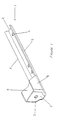
- the housing 1 comprises a longitudinal back plate 2 with low longitudinal extending side flanges 3.
- Bolt holes are formed at spaced intervals along the back plate 2.
- a retaining plate 5 extends transversely to the back plate 2 and is integral with high side flanges 6.
- a fixing hole 7 is provided in the end plate 5.
- a top cover 8 closes off the side flanges and the end plate.
- the other end of the housing is open.
- the fixing hole 7 can be formed as an asymmetrical shape as shown in a way which allows the rotational mounting position of the gas generator to be defined, and thus acts as an orientation feature.
- One such example is shown in figure 1 but many examples of suitable shapes will be evident to one skilled in the art, (e.g. star, hexagon).
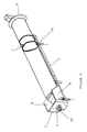
- Figure 2 shows the housing 1 with gas generator 9 attached by a bolt 10 through end plate hole 7.
- the gas generator 9 is prevented from rattling in the housing by a retaining clamp 11 which circumscribes the body of the gas generator and is secured to the housing back plate 2 through holes 4.
- One or more clamps 11 are provided at the open end of the housing 1 and more may be provided along the length of the cylinder.
- the rings may be tightened or adjusted for different cylinder diameters via fixing screws 12.
- the open end of the housing enables different lengths of gas cylinder to be accommodated.
- the housing is particularly versatile. It is also cost effective to produce since the tooling for different unit sizes is saved.
- the housing requires relatively little metal and is thus cheap to produce and lighter than hitherto known housing which substantially surrounded the gas generator.
- the housing is used as an airbag cushion attachment, and for attaching the entire airbag module to a mounting surface.
- the manifold part can be formed asymmetrically to provide parts which are left/right dependent. This can be achieved by using asymmetrically preformed stamping from sheet metal and the housings can then be given unique shapes, particularly adapted on each side to act as an integral manifold to direct the inflation gas and also as an integral heat shield.
Landscapes
- Engineering & Computer Science (AREA)
- Mechanical Engineering (AREA)
- Air Bags (AREA)
Description
- Figure 1
- is a perspective view of a housing according to the invention; and
- Figure 2
- is a perspective view of the housing of Figure 1 with a gas generator mounted.
Claims (10)
- A housing (1) for a gas generator (9) for a vehicle occupant side airbag inflator in a vehicle safety restraint, the housing (1) being formed in one piece and comprising an elongate back plate (2) for supporting the gas generator (9), and having means for mounting to a fixed part of the vehicle, the back plate (2) having, at one end region, integral side flanges (6) extending laterally of the gas generator (9) and, at the other end region, having a retaining clamp (11) fixed to the back plate (2) which is arranged to circumscribe the gas generator (9), to hold the gas generator securely to the housing (1) and thus to a fixed part of the vehicle, and is also adapted as an airbag cushion attachment, characterised in that the housing (1) is asymmetrical about its longitudinal axis.
- A gas generator housing (1) according to claim 1 formed from an asymmetrical stamping of sheet metal.
- A gas generator housing (1) according to claim 1 or 2 comprising an integral inflation gas direction guide.
- A gas generator housing (1) according to any preceding claim having an integral manifold.
- A gas generator housing (1) according to any preceding claim additionally comprising an integral heat shield.
- A gas generator housing (1) according to any preceding claim wherein the end of the housing (1) remote from the side flanges (6) is open so that the housing (1) can accommodate different length gas generators (9).
- A gas generator housing (1) according to any preceding claim wherein the retaining ring (11) is adjustable so as to accommodate different widths of gas generators (9).
- A gas generator housing (1) according to any preceding claim comprising at least one bolt hole (4) formed at spaced intervals along the back plate (2).
- A gas generator housing (1) according to claim 8 wherein the or each bolt hole (4) is formed as an asymmetrical shape which defines the mounting orientation of the housing (1).
- A gas generator housing (1) according to any preceding claim further comprising a retaining plate extending transversely to the back plate (2) integral with the side flanges (6).
Applications Claiming Priority (5)
| Application Number | Priority Date | Filing Date | Title |
|---|---|---|---|
| GBGB9620658.6A GB9620658D0 (en) | 1996-10-03 | 1996-10-03 | Gas generator manifold |
| GB9620658 | 1996-10-03 | ||
| GB9715589A GB2318327B (en) | 1996-10-03 | 1997-07-23 | Gas generator housing |
| GB9715589 | 1997-07-23 | ||
| PCT/GB1997/002540 WO1998014351A1 (en) | 1996-10-03 | 1997-09-19 | Gas generator housing |
Publications (2)
| Publication Number | Publication Date |
|---|---|
| EP0929418A1 EP0929418A1 (en) | 1999-07-21 |
| EP0929418B1 true EP0929418B1 (en) | 2001-11-21 |
Family
ID=26310156
Family Applications (1)
| Application Number | Title | Priority Date | Filing Date |
|---|---|---|---|
| EP97919175A Expired - Lifetime EP0929418B1 (en) | 1996-10-03 | 1997-09-19 | Gas generator housing |
Country Status (6)
| Country | Link |
|---|---|
| US (1) | US6227560B1 (en) |
| EP (1) | EP0929418B1 (en) |
| JP (1) | JP3064288U (en) |
| DE (1) | DE69709767T2 (en) |
| GB (1) | GB2318327B (en) |
| WO (1) | WO1998014351A1 (en) |
Families Citing this family (11)
| Publication number | Priority date | Publication date | Assignee | Title |
|---|---|---|---|---|
| KR100323847B1 (en) * | 2000-02-01 | 2002-02-07 | 이승복 | Structure for fixing inflater for side air bag |
| US6976700B2 (en) * | 2002-11-12 | 2005-12-20 | Trw Vehicle Safety Systems Inc. | Air bag inflator bracket |
| US7121576B2 (en) | 2004-02-27 | 2006-10-17 | Autoliv Asp Inc. | Airbag retention collar for airbag module assembly |
| US20060011495A1 (en) * | 2004-06-28 | 2006-01-19 | Brian Hood | Pyrotechnic safety device and method of use |
| US7318599B2 (en) * | 2004-08-09 | 2008-01-15 | Indiana Mills & Manufacturing Inc. | Modular inflatable restraint apparatus |
| DE102007053101B4 (en) * | 2007-11-07 | 2024-05-16 | Zf Automotive Germany Gmbh | Gas generator and assembly with a gas generator |
| JP5141268B2 (en) * | 2008-01-30 | 2013-02-13 | タカタ株式会社 | Inflator fixing structure and airbag device |
| KR101198842B1 (en) | 2011-05-23 | 2012-11-07 | 기아자동차주식회사 | External air bag module for vehicle and back beam for mounting external air bag module |
| JP5915482B2 (en) * | 2012-09-27 | 2016-05-11 | 豊田合成株式会社 | Intermediate assembly of airbag apparatus and assembly method of airbag apparatus |
| JP6167953B2 (en) * | 2014-03-19 | 2017-07-26 | 豊田合成株式会社 | Air bag device for knee protection |
| US11708043B2 (en) * | 2021-04-20 | 2023-07-25 | Autoliv Asp, Inc. | Inflator bracket |
Family Cites Families (8)
| Publication number | Priority date | Publication date | Assignee | Title |
|---|---|---|---|---|
| US5284358A (en) * | 1992-05-15 | 1994-02-08 | Trw Vehicle Safety Systems Inc. | Air bag assembly |
| US5354093A (en) * | 1993-04-05 | 1994-10-11 | General Motors Corporation | Air bag module having integral cover attachment |
| US5433471A (en) * | 1993-12-13 | 1995-07-18 | General Motors Corporation | Simplified passenger air bag module |
| US5484163A (en) * | 1994-02-17 | 1996-01-16 | Trw Vehicle Safety Systems Inc. | Vehicle occupant restraint apparatus |
| DE4415374A1 (en) * | 1994-05-02 | 1995-11-09 | Trw Repa Gmbh | Airbag module |
| DE19528754A1 (en) * | 1995-08-04 | 1997-02-06 | Trw Repa Gmbh | Airbag restraint module |
| DE19535430A1 (en) * | 1995-09-23 | 1997-03-27 | Vaw Ver Aluminium Werke Ag | Airbag housing |
| DE29613269U1 (en) * | 1996-07-31 | 1996-11-28 | Trw Occupant Restraint Systems Gmbh, 73551 Alfdorf | Airbag module for a vehicle occupant restraint system |
-
1997
- 1997-07-23 GB GB9715589A patent/GB2318327B/en not_active Expired - Fee Related
- 1997-09-19 EP EP97919175A patent/EP0929418B1/en not_active Expired - Lifetime
- 1997-09-19 JP JP1999600003U patent/JP3064288U/en not_active Expired - Lifetime
- 1997-09-19 DE DE69709767T patent/DE69709767T2/en not_active Expired - Fee Related
- 1997-09-19 US US09/269,694 patent/US6227560B1/en not_active Expired - Lifetime
- 1997-09-19 WO PCT/GB1997/002540 patent/WO1998014351A1/en not_active Ceased
Also Published As
| Publication number | Publication date |
|---|---|
| GB2318327A (en) | 1998-04-22 |
| GB9715589D0 (en) | 1997-10-01 |
| WO1998014351A1 (en) | 1998-04-09 |
| EP0929418A1 (en) | 1999-07-21 |
| DE69709767T2 (en) | 2002-08-08 |
| GB2318327B (en) | 2000-11-22 |
| US6227560B1 (en) | 2001-05-08 |
| JP3064288U (en) | 2000-01-07 |
| DE69709767D1 (en) | 2002-02-21 |
Similar Documents
| Publication | Publication Date | Title |
|---|---|---|
| EP0724986B1 (en) | Vehicle seat with an inflatable air cushion | |
| US6227560B1 (en) | Gas generator housing | |
| EP1422104B1 (en) | Occupant protection system | |
| EP0854068B1 (en) | Vehicle seat back frame with airbag module assembly | |
| GB2314537A (en) | Engine-mounting bracket | |
| US6139082A (en) | Cross car beam with adjustable mounting locations | |
| US5261692A (en) | Inflatable restraining device for motor vehicle occupants | |
| US6419304B1 (en) | Interior enclosure for vehicles | |
| GB2334242A (en) | Crash restraint airbag device | |
| US5662350A (en) | Attachment of an air bag module within an instrument panel | |
| JP3272454B2 (en) | Automotive airbag equipment | |
| GB2397806A (en) | Air bag gas generator mounting arrangement | |
| US20030025306A1 (en) | Air bag system mounting structure | |
| JPH10152021A (en) | Buckle fitting tightening device | |
| JP3393756B2 (en) | Occupant protection device | |
| JP3185555B2 (en) | Knee bolster structure | |
| JPH07266995A (en) | Internal structure of vehicle instrument panel | |
| JP3512606B2 (en) | Airbag device for automobile side collision | |
| KR100503246B1 (en) | Mounting structure of passenger air-bag | |
| KR200143414Y1 (en) | Seat belt anchor reinforcement for commercial vehicles | |
| KR200149180Y1 (en) | Air bag attachment structure | |
| EP0885785B1 (en) | Door air bag mounting arrangement | |
| JPH0452122Y2 (en) | ||
| KR100629337B1 (en) | Passenger airbag module | |
| KR0133423Y1 (en) | Vehicle Passenger Airbag Lock |
Legal Events
| Date | Code | Title | Description |
|---|---|---|---|
| PUAI | Public reference made under article 153(3) epc to a published international application that has entered the european phase |
Free format text: ORIGINAL CODE: 0009012 |
|
| 17P | Request for examination filed |
Effective date: 19990216 |
|
| AK | Designated contracting states |
Kind code of ref document: A1 Designated state(s): DE ES FR IT |
|
| 17Q | First examination report despatched |
Effective date: 19990831 |
|
| GRAG | Despatch of communication of intention to grant |
Free format text: ORIGINAL CODE: EPIDOS AGRA |
|
| RTI1 | Title (correction) |
Free format text: GAS GENERATOR HOUSING |
|
| RBV | Designated contracting states (corrected) |
Designated state(s): DE ES FR IT |
|
| GRAG | Despatch of communication of intention to grant |
Free format text: ORIGINAL CODE: EPIDOS AGRA |
|
| GRAH | Despatch of communication of intention to grant a patent |
Free format text: ORIGINAL CODE: EPIDOS IGRA |
|
| GRAH | Despatch of communication of intention to grant a patent |
Free format text: ORIGINAL CODE: EPIDOS IGRA |
|
| GRAA | (expected) grant |
Free format text: ORIGINAL CODE: 0009210 |
|
| AK | Designated contracting states |
Kind code of ref document: B1 Designated state(s): DE ES FR IT |
|
| ET | Fr: translation filed | ||
| REF | Corresponds to: |
Ref document number: 69709767 Country of ref document: DE Date of ref document: 20020221 |
|
| PG25 | Lapsed in a contracting state [announced via postgrant information from national office to epo] |
Ref country code: ES Free format text: LAPSE BECAUSE OF FAILURE TO SUBMIT A TRANSLATION OF THE DESCRIPTION OR TO PAY THE FEE WITHIN THE PRESCRIBED TIME-LIMIT Effective date: 20020530 |
|
| PLBE | No opposition filed within time limit |
Free format text: ORIGINAL CODE: 0009261 |
|
| STAA | Information on the status of an ep patent application or granted ep patent |
Free format text: STATUS: NO OPPOSITION FILED WITHIN TIME LIMIT |
|
| 26N | No opposition filed | ||
| REG | Reference to a national code |
Ref country code: FR Ref legal event code: TP |
|
| PGFP | Annual fee paid to national office [announced via postgrant information from national office to epo] |
Ref country code: IT Payment date: 20070913 Year of fee payment: 11 Ref country code: DE Payment date: 20070928 Year of fee payment: 11 |
|
| PGFP | Annual fee paid to national office [announced via postgrant information from national office to epo] |
Ref country code: FR Payment date: 20070904 Year of fee payment: 11 |
|
| REG | Reference to a national code |
Ref country code: FR Ref legal event code: ST Effective date: 20090529 |
|
| PG25 | Lapsed in a contracting state [announced via postgrant information from national office to epo] |
Ref country code: IT Free format text: LAPSE BECAUSE OF NON-PAYMENT OF DUE FEES Effective date: 20080919 Ref country code: DE Free format text: LAPSE BECAUSE OF NON-PAYMENT OF DUE FEES Effective date: 20090401 |
|
| PG25 | Lapsed in a contracting state [announced via postgrant information from national office to epo] |
Ref country code: FR Free format text: LAPSE BECAUSE OF NON-PAYMENT OF DUE FEES Effective date: 20080930 |