EP0929372B1 - Milling cutter - Google Patents
Milling cutter Download PDFInfo
- Publication number
- EP0929372B1 EP0929372B1 EP97943273A EP97943273A EP0929372B1 EP 0929372 B1 EP0929372 B1 EP 0929372B1 EP 97943273 A EP97943273 A EP 97943273A EP 97943273 A EP97943273 A EP 97943273A EP 0929372 B1 EP0929372 B1 EP 0929372B1
- Authority
- EP
- European Patent Office
- Prior art keywords
- end mill
- head
- tool
- mill head
- center axis
- Prior art date
- Legal status (The legal status is an assumption and is not a legal conclusion. Google has not performed a legal analysis and makes no representation as to the accuracy of the status listed.)
- Expired - Lifetime
Links
Images




Classifications
-
- B—PERFORMING OPERATIONS; TRANSPORTING
- B23—MACHINE TOOLS; METAL-WORKING NOT OTHERWISE PROVIDED FOR
- B23B—TURNING; BORING
- B23B31/00—Chucks; Expansion mandrels; Adaptations thereof for remote control
- B23B31/02—Chucks
- B23B31/10—Chucks characterised by the retaining or gripping devices or their immediate operating means
- B23B31/11—Retention by threaded connection
-
- B—PERFORMING OPERATIONS; TRANSPORTING
- B23—MACHINE TOOLS; METAL-WORKING NOT OTHERWISE PROVIDED FOR
- B23B—TURNING; BORING
- B23B29/00—Holders for non-rotary cutting tools; Boring bars or boring heads; Accessories for tool holders
- B23B29/03—Boring heads
-
- B—PERFORMING OPERATIONS; TRANSPORTING
- B23—MACHINE TOOLS; METAL-WORKING NOT OTHERWISE PROVIDED FOR
- B23C—MILLING
- B23C5/00—Milling-cutters
- B23C5/02—Milling-cutters characterised by the shape of the cutter
- B23C5/10—Shank-type cutters, i.e. with an integral shaft
-
- B—PERFORMING OPERATIONS; TRANSPORTING
- B23—MACHINE TOOLS; METAL-WORKING NOT OTHERWISE PROVIDED FOR
- B23C—MILLING
- B23C5/00—Milling-cutters
- B23C5/28—Features relating to lubricating or cooling
- B23C5/283—Cutting inserts with internal coolant channels
-
- B—PERFORMING OPERATIONS; TRANSPORTING
- B23—MACHINE TOOLS; METAL-WORKING NOT OTHERWISE PROVIDED FOR
- B23Q—DETAILS, COMPONENTS, OR ACCESSORIES FOR MACHINE TOOLS, e.g. ARRANGEMENTS FOR COPYING OR CONTROLLING; MACHINE TOOLS IN GENERAL CHARACTERISED BY THE CONSTRUCTION OF PARTICULAR DETAILS OR COMPONENTS; COMBINATIONS OR ASSOCIATIONS OF METAL-WORKING MACHINES, NOT DIRECTED TO A PARTICULAR RESULT
- B23Q11/00—Accessories fitted to machine tools for keeping tools or parts of the machine in good working condition or for cooling work; Safety devices specially combined with or arranged in, or specially adapted for use in connection with, machine tools
- B23Q11/0042—Devices for removing chips
-
- B—PERFORMING OPERATIONS; TRANSPORTING
- B23—MACHINE TOOLS; METAL-WORKING NOT OTHERWISE PROVIDED FOR
- B23Q—DETAILS, COMPONENTS, OR ACCESSORIES FOR MACHINE TOOLS, e.g. ARRANGEMENTS FOR COPYING OR CONTROLLING; MACHINE TOOLS IN GENERAL CHARACTERISED BY THE CONSTRUCTION OF PARTICULAR DETAILS OR COMPONENTS; COMBINATIONS OR ASSOCIATIONS OF METAL-WORKING MACHINES, NOT DIRECTED TO A PARTICULAR RESULT
- B23Q11/00—Accessories fitted to machine tools for keeping tools or parts of the machine in good working condition or for cooling work; Safety devices specially combined with or arranged in, or specially adapted for use in connection with, machine tools
- B23Q11/10—Arrangements for cooling or lubricating tools or work
- B23Q11/1015—Arrangements for cooling or lubricating tools or work by supplying a cutting liquid through the spindle
- B23Q11/1023—Tool holders, or tools in general specially adapted for receiving the cutting liquid from the spindle
-
- B—PERFORMING OPERATIONS; TRANSPORTING
- B23—MACHINE TOOLS; METAL-WORKING NOT OTHERWISE PROVIDED FOR
- B23C—MILLING
- B23C2210/00—Details of milling cutters
- B23C2210/03—Cutting heads comprised of different material than the shank irrespective of whether the head is detachable from the shank
-
- Y—GENERAL TAGGING OF NEW TECHNOLOGICAL DEVELOPMENTS; GENERAL TAGGING OF CROSS-SECTIONAL TECHNOLOGIES SPANNING OVER SEVERAL SECTIONS OF THE IPC; TECHNICAL SUBJECTS COVERED BY FORMER USPC CROSS-REFERENCE ART COLLECTIONS [XRACs] AND DIGESTS
- Y10—TECHNICAL SUBJECTS COVERED BY FORMER USPC
- Y10T—TECHNICAL SUBJECTS COVERED BY FORMER US CLASSIFICATION
- Y10T279/00—Chucks or sockets
- Y10T279/16—Longitudinal screw clamp
-
- Y—GENERAL TAGGING OF NEW TECHNOLOGICAL DEVELOPMENTS; GENERAL TAGGING OF CROSS-SECTIONAL TECHNOLOGIES SPANNING OVER SEVERAL SECTIONS OF THE IPC; TECHNICAL SUBJECTS COVERED BY FORMER USPC CROSS-REFERENCE ART COLLECTIONS [XRACs] AND DIGESTS
- Y10—TECHNICAL SUBJECTS COVERED BY FORMER USPC
- Y10T—TECHNICAL SUBJECTS COVERED BY FORMER US CLASSIFICATION
- Y10T407/00—Cutters, for shaping
- Y10T407/19—Rotary cutting tool
- Y10T407/1906—Rotary cutting tool including holder [i.e., head] having seat for inserted tool
- Y10T407/1908—Face or end mill
- Y10T407/192—Face or end mill with separate means to fasten tool to holder
-
- Y—GENERAL TAGGING OF NEW TECHNOLOGICAL DEVELOPMENTS; GENERAL TAGGING OF CROSS-SECTIONAL TECHNOLOGIES SPANNING OVER SEVERAL SECTIONS OF THE IPC; TECHNICAL SUBJECTS COVERED BY FORMER USPC CROSS-REFERENCE ART COLLECTIONS [XRACs] AND DIGESTS
- Y10—TECHNICAL SUBJECTS COVERED BY FORMER USPC
- Y10T—TECHNICAL SUBJECTS COVERED BY FORMER US CLASSIFICATION
- Y10T407/00—Cutters, for shaping
- Y10T407/19—Rotary cutting tool
- Y10T407/1906—Rotary cutting tool including holder [i.e., head] having seat for inserted tool
- Y10T407/1908—Face or end mill
- Y10T407/1924—Specified tool shape
-
- Y—GENERAL TAGGING OF NEW TECHNOLOGICAL DEVELOPMENTS; GENERAL TAGGING OF CROSS-SECTIONAL TECHNOLOGIES SPANNING OVER SEVERAL SECTIONS OF THE IPC; TECHNICAL SUBJECTS COVERED BY FORMER USPC CROSS-REFERENCE ART COLLECTIONS [XRACs] AND DIGESTS
- Y10—TECHNICAL SUBJECTS COVERED BY FORMER USPC
- Y10T—TECHNICAL SUBJECTS COVERED BY FORMER US CLASSIFICATION
- Y10T407/00—Cutters, for shaping
- Y10T407/19—Rotary cutting tool
- Y10T407/1946—Face or end mill
- Y10T407/1948—Face or end mill with cutting edge entirely across end of tool [e.g., router bit, end mill, etc.]
-
- Y—GENERAL TAGGING OF NEW TECHNOLOGICAL DEVELOPMENTS; GENERAL TAGGING OF CROSS-SECTIONAL TECHNOLOGIES SPANNING OVER SEVERAL SECTIONS OF THE IPC; TECHNICAL SUBJECTS COVERED BY FORMER USPC CROSS-REFERENCE ART COLLECTIONS [XRACs] AND DIGESTS
- Y10—TECHNICAL SUBJECTS COVERED BY FORMER USPC
- Y10T—TECHNICAL SUBJECTS COVERED BY FORMER US CLASSIFICATION
- Y10T407/00—Cutters, for shaping
- Y10T407/23—Cutters, for shaping including tool having plural alternatively usable cutting edges
-
- Y—GENERAL TAGGING OF NEW TECHNOLOGICAL DEVELOPMENTS; GENERAL TAGGING OF CROSS-SECTIONAL TECHNOLOGIES SPANNING OVER SEVERAL SECTIONS OF THE IPC; TECHNICAL SUBJECTS COVERED BY FORMER USPC CROSS-REFERENCE ART COLLECTIONS [XRACs] AND DIGESTS
- Y10—TECHNICAL SUBJECTS COVERED BY FORMER USPC
- Y10T—TECHNICAL SUBJECTS COVERED BY FORMER US CLASSIFICATION
- Y10T407/00—Cutters, for shaping
- Y10T407/27—Cutters, for shaping comprising tool of specific chemical composition
-
- Y—GENERAL TAGGING OF NEW TECHNOLOGICAL DEVELOPMENTS; GENERAL TAGGING OF CROSS-SECTIONAL TECHNOLOGIES SPANNING OVER SEVERAL SECTIONS OF THE IPC; TECHNICAL SUBJECTS COVERED BY FORMER USPC CROSS-REFERENCE ART COLLECTIONS [XRACs] AND DIGESTS
- Y10—TECHNICAL SUBJECTS COVERED BY FORMER USPC
- Y10T—TECHNICAL SUBJECTS COVERED BY FORMER US CLASSIFICATION
- Y10T408/00—Cutting by use of rotating axially moving tool
- Y10T408/89—Tool or Tool with support
- Y10T408/907—Tool or Tool with support including detailed shank
Definitions
- the present invention relates to a tool and a tool head according to the preambles of claims 1 and 5.
- a previously known end mill with a detachable head is disclosed in JP patent document No. 57-189713.
- the known tool includes a neck portion that is integral with the end mill head, which neck portion constitutes a potential breakage area for the tool.
- Another problem with such prior art is that it has been found unstable in some high speed applications, due to the lack of support at radially outward surfaces.
- unnecessarily expensive tool material is used in the neck portion.
- US-A-4,964,762 on which the preambles of the independent claims 1 and 5 are based, discloses a face milling cutter having indexable cutting inserts.
- An object of the present invention is to provide an end mill in which performance and useful life are improved.
- Another object of the present invention is to provide an end mill that has an extremely good stability such that a machined surface can be obtained which is substantially free from chatter marks.
- Still another object of the present invention is to provide an easily mountable end mill.
- Still another object of the present invention is to provide an end mill, which due to its configuration saves expensive cutting tool material.
- Figs. 1A and 1B show an embodiment of a detachable ball nose end mill 10 according to the present invention.
- the end mill 10 comprises a mill head 11, a pull rod or screw 12 and a shank 13.
- the pull rod 12 is threaded into the mill head 11 and the pull rod is further connected to the shank 13.
- the shank is preferably held in a rotatable spindle in a milling or drilling machine, not shown.
- the shank 13 has a hole 14 into which the pull rod 12 is fitted.
- the end mill head 11 has cutting edge means 15, such as two identical cutting edges 16 extending at least from the outermost point of the head towards the center axis 17 of the tool.
- the cutting edge means 15 may alternatively include three or four identical cutting edges.
- the cutting edges 16 preferably meet in the vicinity of the center axis 17.
- the end mill head and the shank comprise cooperating abutment surfaces 19 and 20.
- the abutment surfaces are preferably planar and extend generally perpendicularly to the center axis 17 of the end mill.
- the cutting edge means 15 follow a path, which is larger than 180° so as to allow outcopying during upwardly directed feed.
- the path is preferably circular and its largest diameter is larger than the diameter of the abutment surface 19 and the diameter of the shank.
- the largest diameter of the abutment surface 19 of the mill head and the outer diameter of the abutment surface 20 of the shank are substantially identical.
- Each cutting edge 16 lies in a plane P which forms an acute angle ⁇ with the center axis 17, when seen in a view as shown in Fig. 3B.
- the angle ⁇ is 5 to 15°, preferably about 10°.
- the pull rod 12 is separable from the end mill head by means of threads 18 or bayonet means, the latter not shown.
- the end mill head does not extend axially rearwards of the plane of the surfaces 19 and 20.
- the pull rod and the end mill head comprise conical cooperating centering surfaces 21 and 22.
- the centering surfaces 21 and 22 taper at an acute angle ⁇ relative to the center axis 17 towards an axially forward free end 34 of the pull rod, Fig. 1B.
- the angle ⁇ is between 1 to 20°, preferably 5 to 10°.
- the end mill head is made from material harder than the material of the pull rod.
- the end mill head is manufactured by mixing powder of sintered hard alloy or cermet with an organic binder such as plastics and forming the mixture to pellets or granulates, moulding the pellets or granulates according to an injection moulding process and sintering the obtained product at a temperature of 1300 to 1500°C.
- the pull rod is preferably made from steel, which is relatively inexpensive.
- the free ends of the pull rod comprise fastening means, such as threads 23 and 25 and/or bayonet means, for engagement with corresponding fastening means 18 and 24, respectively, in the end mill head and in the shank.
- the end mill head has holes 26 for promoting pressurized medium, such as air or liquid, to remove chips and the medium is supplied from the tool holder, not shown.
- the end mill head comprises external key grip means 27 for mounting and dismounting.
- the end mill head 11 for cutting material during its revolution about the center axis 17 further comprises clearance means 28, a first recess 29, having centering means 22 therein, and a second recess 30, having fastening means 18 therein.
- At least two substantially parallel flushing channels 26 are provided in the end mill head, extending from the second recess 30 and terminating in chip flutes or rake faces 31 of the end mill head.
- the recesses 29, 30 make a penetrated blind hole, i.e. a hole with a certain depth at which the flushing channels 26 connect. Said hole has a substantially decreasing cross-sectional area in direction towards the cutting edge means 15.
- the elongated pull rod to be used in the rotatable ballnose end mill further comprises key grip means 32 and 33, such as hexagon wrench holes for Allen keys, at the first free end 34 and a second free end 35, respectively.
- the centering surface 21 is provided closer to the first free end 34 than to the second free end 35 of the pull rod.
- the diameter of the first free end 34 is smaller than the diameter of the second free end 35.
- a longitudinally extending hole 36 is provided in the pull rod, said hole extending from one free end to another for the promotion of pressurized medium, such as liquid or air. Medium to remove chips is supplied through the hole 36 and the flush channels.
- the pull rod 12 is mounted by inserting the rod into the hole 14 of the shank 13 and by rotating the rod with a key, not shown, in the grip 32 or 33 to a predetermined depth.
- the threads 25 of the rod will then engage the threads 24 of the shank.
- the portions 37 and 38 are manufactured with small tolerances so as to provide a slip fit and to minimize relative radial movement.
- at least one of the threads 24 and 25 is provided with a locking medium, such as plastics, so as to increase the resistance against unscrewing.
- the end mill head 11 is then placed over the free end 34 of the rod and is rotated such that the engagement of threads 18 and 23 draw the head axially towards the shank until the centering surfaces 21 and 22 engage and center the mill head. Further rotation of the head, by means of a wrench acting externally on the key grip means 27, will result in rotation also of the rod 12 until the abutment surfaces 19 and 20 will come into contact and stop further axial movement of rod and head.
- Figs. 7A through 13 an alternative embodiment of a tool according to the present invention will be described. It is understood that like numerals depict like details as described in connection with the previous embodiment.
- Figs 9A and 9B show an embodiment of a detachable ball nose end mill 10 comprising a mill head 11', a pull rod or screw 12' and a shank 13'.
- the pull rod 12' is screwn into the mill head 11' and the pull rod is further connected to the shank 13'.
- the shank 13' has a hole 14' into which the pull rod 12' is fitted.
- the end mill head 11' has cutting edge means 15' such as two identical cutting edges 16' extending at least from the outermost point of the head towards the center axis 17' of the tool.
- the cutting edge means 15' may alternatively include three or four identical cutting edges.
- the cutting edges 16' preferably meet in the vicinity of the center axis 17'.
- the end mill head and the shank comprise cooperating abutment surfaces 19' and 20'.
- the abutment surfaces are preferably planar and extend generally perpendicularly to the center axis 17' of the end mill.
- the cutting edge means 15' follow a path, which is larger than 180° so as to allow outcopying during upwardly directed feed.
- the path is preferably circular and its largest diameter is larger than the diameter of the abutment surface 19' and the diameter of the shank.
- the largest diameter of the abutment surface 19' of the mill head and the outer diameter of the abutment surface 20' of the shank are substantially equal.
- Each cutting edge 16' lies in a plane P' which forms an acute angle ⁇ ' with the center axis 17', when seen in a view as shown in Fig. 9B.
- the angle ⁇ ' is 5 to 15°, preferably about 10°.
- the pull rod 12' is separable from the end mill head by means of threads 18' or bayonet means, the latter not shown.
- the end mill head extend partially axially rearwards of the plane of the surfaces 19' and 20'.
- the shank and the end mill head comprise substantially cylindrical cooperating centering surfaces 21' and 22', respectively.
- the centering surface 21' of the shank is located in a recess 40' in the forward free end of the shank.
- the centering surface 22' of the mill head is located externally on a projection 41' extending rearwardly of the abutment surface 19', a distance L.
- the centering surfaces 21' and 22' extend substantially parallel to the center axis 17'.
- the end mill head is made from material harder than the material of the pull rod. The threads 25' of the rod will then engage the threads 24' of the shank.
- the end mill head is manufactured by mixing powder of sintered hard alloy or cermet with an organic binder such as plastics and forming the mixture to pellets or granulates, molding the pellets or granulates according to an injection molding process and sintering the obtained product at a temperature of 1300 to 1500°C.
- the pull rod is preferably made from steel, which is relatively inexpensive.
- the free ends of the pull rod comprise fastening means, such as threads 23' and 25' and/or bayonet means, for engagement with corresponding fastening means 18' and 24', respectively, in the end mill head and in the shank.
- the end mill head has holes 26' for promoting pressurized medium, such as air or liquid, to remove chips and the medium is supplied from the tool holder, not shown.
- the end mill head comprises external key grip means 27' for mounting and dismounting.
- the end mill head 11' for cutting material during its revolution about the center axis 17' further comprises clearance means 28', a first recess 29', having centering means 22' therein, and a second recess 30, having fastening means 18' therein.
- At least two flushing channels 26' are provided in the end mill head, extending from the second recess 30' and terminating in chip flutes or rake faces 31' of the end mill head.
- the elongated pull rod to be used in the rotatable ballnose end mill further comprises key grip means, such as hexagon wrench holes for Allen keys, at the first free end 34' and a second free end 35', respectively.
- the diameter of the first free end 34' is smaller than the diameter of the second free end 35'.
- a longitudinally extending hole 36' is provided in the pull rod, said hole extending from one free end to another for the promotion of pressurized medium, such as liquid or air. Medium to remove chips is supplied through the hole 36' and the flush holes 26'.
- the pull rod 12' is mounted by inserting it into the hole 14' of the shank 13' and by rotating the rod with a key, not shown, from the front or from the rear into the grip means 32' or 33', respectively, to a predetermined depth.
- the threads 25' of the rod will then engage the threads 24' of the shank.
- the end mill head 11' is then placed over the free end 34' of the rod and is rotated such that the engagement of threads 18' and 23' draw the head axially towards the shank until the centering surfaces 21' and 22' engage and center the mill head.
- the surfaces 21' and 22' are manufactured with small tolerances so as to provide a slip fit and to minimize relative radial movement.
- at least one of the threads 24' and 25' is provided with a locking medium, such as plastics, so as to increase the resistance against unscrewing.
- the end mill heads are preferably made in injection moulded tungsten carbide and have integrated threads placed axially forwards of the planar abutment surfaces.
- the mill head describes the largest diameter of the entire tool.
- the pull rods are externally threaded at all free ends and they include a central channel for distribution of a flush medium to be transferred to a widened space and successively through the flush channels to the cutting edge area.
- the pull rod is positioned in the vicinity of the forward end of each shank. There are key grips for rotation of each end mill head during assembling.
- each embodiment of the tool according to the present invention differ in that in the first case the centering surfaces are positioned internally in the mill head and externally on the pull rod while tapering forwardly. In the other case, the centering surfaces are positioned externally on the mill head and internally on the shank while being parallel with the rotational axis of the tool.
Landscapes
- Engineering & Computer Science (AREA)
- Mechanical Engineering (AREA)
- Milling Processes (AREA)
Abstract
Description
- The present invention relates to a tool and a tool head according to the preambles of claims 1 and 5.
- A previously known end mill with a detachable head is disclosed in JP patent document No. 57-189713. The known tool includes a neck portion that is integral with the end mill head, which neck portion constitutes a potential breakage area for the tool. Another problem with such prior art is that it has been found unstable in some high speed applications, due to the lack of support at radially outward surfaces. In addition unnecessarily expensive tool material is used in the neck portion. US-A-4,964,762, on which the preambles of the independent claims 1 and 5 are based, discloses a face milling cutter having indexable cutting inserts.
- An object of the present invention is to provide an end mill in which performance and useful life are improved.
- Another object of the present invention is to provide an end mill that has an extremely good stability such that a machined surface can be obtained which is substantially free from chatter marks.
- Still another object of the present invention is to provide an easily mountable end mill.
- Still another object of the present invention is to provide an end mill, which due to its configuration saves expensive cutting tool material.
- The present invention will be explained in more detail by referring to the accompanying drawings, wherein:
- Fig. 1A is an exploded and sectioned side view showing an embodiment of a ball end mill according to the present invention,
- Fig. 1B is a magnified side view showing the ball end mill of Fig. 1A as assembled,
- Fig. 2 is a top view of an end mill head according to the present invention,
- Figs. 3A and 3B are side views of the end mill head,
- Fig. 4 is a bottom view of a lower side of the end mill head,
- Fig. 5 is a cross-sectional view of the end mill head along line V-V in Fig. 3A,
- Fig. 6 is a perspective view of the end mill head.
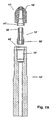
- Fig. 7A is an exploded and sectioned side view an alternative embodiment of a ball end mill according to the present invention.
- Fig. 7B is a magnified side view showing the ball end mill of Fig. 7A as assembled,
- Fig. 8 is a top view of an alternative end mill head according to the present invention,
- Figs. 9A and 9B are side views of the alternative end mill head,
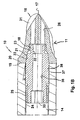
- Fig. 10 is a bottom view of a lower side of the alternative end mill head,
- Fig. 11 is a cross-sectional view of the alternative end mill head.
- Fig. 12 is a cross-sectional view of the alternative end mill head along line XII-XII in Fig. 11A,
- Fig. 13 is a perspective view of the alternative end mill head.
-
- Figs. 1A and 1B show an embodiment of a detachable ball
nose end mill 10 according to the present invention. Theend mill 10 comprises amill head 11, a pull rod orscrew 12 and ashank 13. Thepull rod 12 is threaded into themill head 11 and the pull rod is further connected to theshank 13. The shank is preferably held in a rotatable spindle in a milling or drilling machine, not shown. Theshank 13 has ahole 14 into which thepull rod 12 is fitted. Theend mill head 11 has cutting edge means 15, such as twoidentical cutting edges 16 extending at least from the outermost point of the head towards thecenter axis 17 of the tool. The cutting edge means 15 may alternatively include three or four identical cutting edges. Thecutting edges 16 preferably meet in the vicinity of thecenter axis 17. The end mill head and the shank comprise cooperatingabutment surfaces center axis 17 of the end mill. Preferably the cutting edge means 15 follow a path, which is larger than 180° so as to allow outcopying during upwardly directed feed. The path is preferably circular and its largest diameter is larger than the diameter of theabutment surface 19 and the diameter of the shank. The largest diameter of theabutment surface 19 of the mill head and the outer diameter of theabutment surface 20 of the shank are substantially identical. Eachcutting edge 16 lies in a plane P which forms an acute angle β with thecenter axis 17, when seen in a view as shown in Fig. 3B. The angle β is 5 to 15°, preferably about 10°. Thepull rod 12 is separable from the end mill head by means ofthreads 18 or bayonet means, the latter not shown. The end mill head does not extend axially rearwards of the plane of thesurfaces centering surfaces centering surfaces center axis 17 towards an axially forwardfree end 34 of the pull rod, Fig. 1B. The angle α is between 1 to 20°, preferably 5 to 10°. The end mill head is made from material harder than the material of the pull rod. The end mill head is manufactured by mixing powder of sintered hard alloy or cermet with an organic binder such as plastics and forming the mixture to pellets or granulates, moulding the pellets or granulates according to an injection moulding process and sintering the obtained product at a temperature of 1300 to 1500°C. The pull rod is preferably made from steel, which is relatively inexpensive. The free ends of the pull rod comprise fastening means, such asthreads holes 26 for promoting pressurized medium, such as air or liquid, to remove chips and the medium is supplied from the tool holder, not shown. The end mill head comprises external key grip means 27 for mounting and dismounting. - The
end mill head 11 for cutting material during its revolution about thecenter axis 17 further comprises clearance means 28, afirst recess 29, having centering means 22 therein, and asecond recess 30, having fastening means 18 therein. At least two substantiallyparallel flushing channels 26 are provided in the end mill head, extending from thesecond recess 30 and terminating in chip flutes or rake faces 31 of the end mill head. Therecesses flushing channels 26 connect. Said hole has a substantially decreasing cross-sectional area in direction towards the cutting edge means 15. - The elongated pull rod to be used in the rotatable ballnose end mill further comprises key grip means 32 and 33, such as hexagon wrench holes for Allen keys, at the first
free end 34 and a secondfree end 35, respectively. The centeringsurface 21 is provided closer to the firstfree end 34 than to the secondfree end 35 of the pull rod. The diameter of the firstfree end 34 is smaller than the diameter of the secondfree end 35. A longitudinally extendinghole 36 is provided in the pull rod, said hole extending from one free end to another for the promotion of pressurized medium, such as liquid or air. Medium to remove chips is supplied through thehole 36 and the flush channels. - Now, a mounting and dismounting method for the detachable ball nose end mill will be described below primarily in connection with Figs. 1A and 1B. The
pull rod 12 is mounted by inserting the rod into thehole 14 of theshank 13 and by rotating the rod with a key, not shown, in thegrip threads 25 of the rod will then engage thethreads 24 of the shank. Theportions threads - The
end mill head 11 is then placed over thefree end 34 of the rod and is rotated such that the engagement ofthreads surfaces rod 12 until the abutment surfaces 19 and 20 will come into contact and stop further axial movement of rod and head. - In an alternative mounting procedure the end mill head and the pull rod are joined together such that the centering surfaces 21, 22 engage and then the rod and the head are threaded as a unit into the
shank hole 14, until the abutment surfaces 19, 20 engage and stop further axial movement of rod and head. - The above-described threads are provided such that the forces acting on the cutting edge means 15 will tend to further tighten them if not already tightened. This will also be the case if an alternative fastening means, for example a bayonet coupling, is used.
- When the cutting edge means 15 has become worn and the
head 11 shall be replaced, then the above procedure concerning the head, is reversed. Since thethreads rod 12. - An alternative, preferable, method for mounting and dismounting the detachable ball nose end mill is hereinafter described. First, the head and the pull rod are joined together via the
threads shank hole 14, until the abutment surfaces 19, 20 engage and stop further axial movement of rod and head. - Referring now to Figs. 7A through 13, an alternative embodiment of a tool according to the present invention will be described. It is understood that like numerals depict like details as described in connection with the previous embodiment. Figs 9A and 9B show an embodiment of a detachable ball
nose end mill 10 comprising a mill head 11', a pull rod or screw 12' and a shank 13'. The pull rod 12' is screwn into the mill head 11' and the pull rod is further connected to the shank 13'. The shank 13' has a hole 14' into which the pull rod 12' is fitted. The end mill head 11' has cutting edge means 15' such as two identical cutting edges 16' extending at least from the outermost point of the head towards the center axis 17' of the tool. The cutting edge means 15' may alternatively include three or four identical cutting edges. The cutting edges 16' preferably meet in the vicinity of the center axis 17'. The end mill head and the shank comprise cooperating abutment surfaces 19' and 20'. The abutment surfaces are preferably planar and extend generally perpendicularly to the center axis 17' of the end mill. Preferably the cutting edge means 15' follow a path, which is larger than 180° so as to allow outcopying during upwardly directed feed. The path is preferably circular and its largest diameter is larger than the diameter of theabutment surface 19' and the diameter of the shank. The largest diameter of theabutment surface 19' of the mill head and the outer diameter of the abutment surface 20' of the shank are substantially equal. Each cutting edge 16' lies in a plane P' which forms an acute angle β' with the center axis 17', when seen in a view as shown in Fig. 9B. The angle β' is 5 to 15°, preferably about 10°. The pull rod 12' is separable from the end mill head by means of threads 18' or bayonet means, the latter not shown. The end mill head extend partially axially rearwards of the plane of thesurfaces 19' and 20'. The shank and the end mill head comprise substantially cylindrical cooperating centering surfaces 21' and 22', respectively. The centering surface 21' of the shank is located in a recess 40' in the forward free end of the shank. The centering surface 22' of the mill head is located externally on a projection 41' extending rearwardly of theabutment surface 19', a distance L. The centering surfaces 21' and 22' extend substantially parallel to the center axis 17'. The end mill head is made from material harder than the material of the pull rod. The threads 25' of the rod will then engage the threads 24' of the shank. The end mill head is manufactured by mixing powder of sintered hard alloy or cermet with an organic binder such as plastics and forming the mixture to pellets or granulates, molding the pellets or granulates according to an injection molding process and sintering the obtained product at a temperature of 1300 to 1500°C. The pull rod is preferably made from steel, which is relatively inexpensive. The free ends of the pull rod comprise fastening means, such as threads 23' and 25' and/or bayonet means, for engagement with corresponding fastening means 18' and 24', respectively, in the end mill head and in the shank. The end mill head has holes 26' for promoting pressurized medium, such as air or liquid, to remove chips and the medium is supplied from the tool holder, not shown. The end mill head comprises external key grip means 27' for mounting and dismounting. - The end mill head 11' for cutting material during its revolution about the center axis 17' further comprises clearance means 28', a first recess 29', having centering means 22' therein, and a
second recess 30, having fastening means 18' therein. At least two flushing channels 26' are provided in the end mill head, extending from the second recess 30' and terminating in chip flutes or rake faces 31' of the end mill head. - The elongated pull rod to be used in the rotatable ballnose end mill further comprises key grip means, such as hexagon wrench holes for Allen keys, at the first free end 34' and a second free end 35', respectively. The diameter of the first free end 34' is smaller than the diameter of the second free end 35'. A longitudinally extending hole 36' is provided in the pull rod, said hole extending from one free end to another for the promotion of pressurized medium, such as liquid or air. Medium to remove chips is supplied through the hole 36' and the flush holes 26'.
- Now, a mounting and dismounting method for the detachable ball nose end mill will be described below primarily in connection with Figs. 7A and 7B. The pull rod 12' is mounted by inserting it into the hole 14' of the shank 13' and by rotating the rod with a key, not shown, from the front or from the rear into the grip means 32' or 33', respectively, to a predetermined depth. The threads 25' of the rod will then engage the threads 24' of the shank.
- The end mill head 11' is then placed over the free end 34' of the rod and is rotated such that the engagement of threads 18' and 23' draw the head axially towards the shank until the centering surfaces 21' and 22' engage and center the mill head. The surfaces 21' and 22' are manufactured with small tolerances so as to provide a slip fit and to minimize relative radial movement. Preferably at least one of the threads 24' and 25' is provided with a locking medium, such as plastics, so as to increase the resistance against unscrewing. Further rotation of the head, by means of a wrench acting externally on the key grip means 27', will result in rotation also of the rod 12' until the abutment surfaces 19' and 20' will come in contact and stop further axial movement of rod and head.
- The above-described threads are provided such that the forces acting on the cutting edge means 15' will tend to further tighten them if not already tightened. This will also be the case if an alternative fastening means, for example a bayonet coupling, is used.
- When the cutting edge means 15' has become worn and the head 11' shall be replaced, then the above procedure concerning the head, is reversed. Since the threads 24' and 25' are more tightly interconnected due to the locking medium, these threads will not unscrew during unscrewing the head. Therefore a new head may be mounted without loosening the rod 12'.
- An alternative, preferable, method for mounting and dismounting the detachable ball nose end mill is hereinafter described. First, the head and the pull rod are joined together via the threads 18' and 23' preferably until the rod reaches the bottom of the thread 18'. Then the rod and the head are threaded as a unit into the shank hole 14', until the abutment surfaces 19', 20' engage and stop further axial movement of rod and head.
- There are several common features in the two embodiments of a tool according to the present invention, described above. The end mill heads are preferably made in injection moulded tungsten carbide and have integrated threads placed axially forwards of the planar abutment surfaces. The mill head describes the largest diameter of the entire tool. There is provided only a frictional connection between the mill head and the shank in the rotational direction of the tool. The pull rods are externally threaded at all free ends and they include a central channel for distribution of a flush medium to be transferred to a widened space and successively through the flush channels to the cutting edge area. The pull rod is positioned in the vicinity of the forward end of each shank. There are key grips for rotation of each end mill head during assembling.
- The centering principals however, of each embodiment of the tool according to the present invention differ in that in the first case the centering surfaces are positioned internally in the mill head and externally on the pull rod while tapering forwardly. In the other case, the centering surfaces are positioned externally on the mill head and internally on the shank while being parallel with the rotational axis of the tool.
- Although the present invention has been described in connection with preferred embodiments thereof, it will be appreciated by those skilled in the art that additions, deletions, modifications, and substitutions not specifically described may be made without departing from the scope of the invention as defined in the appended claims.
Claims (8)
- A tool (10;10') comprising a tool head (11;11'), a pull rod (12;12') and a shank (13;13') having a hole (14;14') into which the pull rod is fitted, said tool head having a cutting edge means (15;15') and fastening means (18;18'), said tool head (11;11') comprising radial centering means (22;22'), said tool having a center axis (17;17'), said pull rod (12;12') being separable from the tool head (11;11'), said tool head and said shank (13;13') comprising cooperating abutment surfaces (19,20;19',20'), said abutment surfaces extending generally perpendicularly to the center axis (17;17') of the tool, said radial centering means (22;22') being provided substantially radially inwardly of said abutment surface (19;19'),
characterized in that the tool is an end mill (10;10') having an end mill head (11;11') made of tungsten carbide and that the fastening means (18;18') and the cutting edge means (15;15') are integral with the end mill head. - The tool according to claim 1,
characterized in that the entire end mill head is made from a material harder than the material of the pull rod and that free ends of the pull rod comprise fastening means, such as threads and/or bayonet means, for engagement with corresponding fastening means in the end mill head and in the shank and that the end mill head (11) and the pull rod (12) comprise cooperating centering surfaces (21,22), said centering surfaces tapering forwardly at an acute angle (α) relative to said center axis (17) or that the end mill head (11') and the shank (13') comprise cooperating centering surfaces (21',22'), said centering surfaces being substantially parallel with said center axis (17'). - The tool according to claims 1 or 2,
characterized in that the end mill includes flush channels for promoting pressurized medium, such as air or liquid, to remove chips and that the medium is supplied from a first channel (14;14') in the shank (13;13') through a second channel (36;36') in the pull rod (12;12') and further through third channels (26;26') in the end mill head (11;11') via an intermediate widened space (30;30') in the end mill head. - The tool according to claims 1, 2 or 3,
characterized in that the cutting edge means (15;15') encloses a path which is larger than 180° and that the material of the end mill head (11;11') is an injection moulded, sintered hard alloy and that the end mill head comprises external key grip means (27;27') for mounting and dismounting and that the cutting edge means (15;15'), such as two identical cutting edges (16;16'), extend at least from the outermost point of the head towards the center axis (17;17') and that the cutting edges preferably meet in the vicinity of the center axis. - A tool head for the tool according to claim 1 for cutting material during its revolution about a center axis (17;17') comprising cutting means (15;15'), clearance means (28;28') and fastening means (18;18'), said tool head (11;11') comprising radial centering means (22;22'), said tool head comprising an abutment surface (19;19'), said abutment surface extending generally perpendicularly to the center axis (17;17'), said radial centering means (22;22') being provided substantially radially inwardly of said abutment surface (19;19'),
characterized in that the tool head is an end mill head (11;11') made of tungsten carbide and that the fastening means (18;18') and the cutting edge means (15;15') are integral with the end mill head. - The tool head according to claim 5,
characterized in that the cutting means (15;15'), such as two identical cutting edges (16;16'), extend at least from the outermost point of the head towards the center axis (17;17') and that the cutting edges preferably meet in the vicinity of the center axis and that the centering means (22;22') tapers forwardly at an acute angle (α) relative to the center axis (17) or is substantially parallel with the center axis (17'). - The tool head according to claim 6,
characterized in that the cutting means (15;15') enclose a path which is larger than 180° and that the material of the end mill head is an injection moulded, sintered hard alloy and that the end mill head comprises external key grip means (27;27') and that the fastening means (18;18') comprises threads or bayonet means arranged substantially forwardly of the abutment surface (22;22') and that at least two flushing channels (26;26') are provided in the end mill head, extending from a first recess (30;30') to rake faces (31) or clearance faces (28') of the end mill head. - The tool head according to claim 5 or 6,
characterized in that the centering surface (22') of the mill head (11') is located externally on a projection (41') extending a distance (L) rearwardly of the abutment surface (19').
Applications Claiming Priority (3)
| Application Number | Priority Date | Filing Date | Title |
|---|---|---|---|
| SE9603525A SE509931C2 (en) | 1996-09-27 | 1996-09-27 | Swivel mill, swivel head and method of mounting a removable swivel head on a shaft for a swivel |
| SE9603525 | 1996-09-27 | ||
| PCT/SE1997/001624 WO1998013161A1 (en) | 1996-09-27 | 1997-09-25 | Milling cutter |
Publications (2)
| Publication Number | Publication Date |
|---|---|
| EP0929372A1 EP0929372A1 (en) | 1999-07-21 |
| EP0929372B1 true EP0929372B1 (en) | 2004-07-21 |
Family
ID=20404045
Family Applications (1)
| Application Number | Title | Priority Date | Filing Date |
|---|---|---|---|
| EP97943273A Expired - Lifetime EP0929372B1 (en) | 1996-09-27 | 1997-09-25 | Milling cutter |
Country Status (8)
| Country | Link |
|---|---|
| US (1) | US5899642A (en) |
| EP (1) | EP0929372B1 (en) |
| JP (1) | JP2001500801A (en) |
| KR (1) | KR100501862B1 (en) |
| CN (1) | CN1086618C (en) |
| DE (1) | DE69729945T2 (en) |
| SE (1) | SE509931C2 (en) |
| WO (1) | WO1998013161A1 (en) |
Families Citing this family (63)
| Publication number | Priority date | Publication date | Assignee | Title |
|---|---|---|---|---|
| SE509207C2 (en) * | 1995-05-04 | 1998-12-14 | Seco Tools Ab | Tools for cutting machining |
| KR100309968B1 (en) * | 1998-02-05 | 2001-10-29 | 니시무로 타이죠 | End mill and cutting method using the same |
| SE519123C2 (en) | 1998-12-22 | 2003-01-14 | Seco Tools Ab | Cuts and tools for cutting machining and method of mounting cutters therein |
| SE9804459L (en) * | 1998-12-22 | 2000-01-17 | Seco Tools Ab | Tools and cutting heads for cutting machining |
| DE19910580C1 (en) * | 1999-03-10 | 2000-07-27 | Tigra Hartstoff Gmbh | End mill blank made of hard material |
| ES2190977T3 (en) | 1999-06-15 | 2003-09-01 | Franz-Josef Pokolm | TOOL FOR MECHANIZATION BY STARTING OF VIRUTES. |
| DE29910468U1 (en) * | 1999-06-15 | 2000-08-17 | Pokolm, Franz-Josef, 33428 Harsewinkel | Tool for machining, in particular steel workpieces |
| IL136032A (en) * | 2000-05-09 | 2003-12-10 | Iscar Ltd | Tool joint |
| IL137316A (en) * | 2000-07-16 | 2004-01-04 | Iscar Ltd | Cutting tool assembly |
| ES2295190T3 (en) * | 2000-08-18 | 2008-04-16 | Iscar Ltd. | CUTTING TOOL SET. |
| US6565291B2 (en) | 2000-08-18 | 2003-05-20 | Iscar, Ltd. | Cutting tool assembly |
| IL158514A0 (en) * | 2001-04-23 | 2004-05-12 | Amaxa Gmbh | Buffer solution for electroporation and a method comprising the use of the same |
| US6485235B1 (en) | 2001-05-08 | 2002-11-26 | Allied Machine & Engineering Corp. | Cutting tool assembly with replaceable cutting head |
| DE20119569U1 (en) * | 2001-12-01 | 2002-02-14 | AKE Knebel GmbH & Co., 72336 Balingen | Device for holding tools |
| JP4378931B2 (en) * | 2002-03-04 | 2009-12-09 | 三菱マテリアル株式会社 | Blade part replaceable cutting tool and blade part mounted on the cutting tool |
| IL150013A (en) * | 2002-06-04 | 2007-06-17 | Gil Hecht | Rotary cutting tool |
| SE526762C2 (en) * | 2002-06-17 | 2005-11-01 | Sandvik Intellectual Property | He / she connection showing press fit between the parts |
| US7039994B2 (en) * | 2003-02-14 | 2006-05-09 | Diamond Z Manufacturing | Mill rod puller |
| JP2005034939A (en) * | 2003-07-14 | 2005-02-10 | Hitachi Tool Engineering Ltd | Cutting edge member, tool holder and cutting tool |
| SE526392C2 (en) * | 2003-08-28 | 2005-09-06 | Seco Tools Ab | Tool arrangement and chip cutting tools where the tool has a channel of non-circular cross section |
| DE102004010372A1 (en) * | 2004-03-03 | 2005-09-22 | Gühring, Jörg, Dr. | Tool for deburring holes |
| US7325471B2 (en) * | 2004-09-07 | 2008-02-05 | Kennametal Inc. | Toolholder and cutting insert for a toolholder assembly |
| SE528245C2 (en) | 2004-09-23 | 2006-10-03 | Seco Tools Ab | Tool head with mounting section with axial and radial stop surfaces |
| SE528251C2 (en) * | 2004-09-24 | 2006-10-03 | Seco Tools Ab | Trade for tools and tools with a transition part between a threaded part and a supporting part |
| SE528299C2 (en) * | 2004-09-24 | 2006-10-17 | Seco Tools Ab | Cutting tip and cutting tool with holder part designed as truncated conical thread |
| ATE475666T1 (en) * | 2005-12-07 | 2010-08-15 | Avecia Biotechnology Inc | METHOD FOR PRODUCING POLY(ALKOXYLATED) OLIGONUCLEOTIDES |
| IL173877A (en) * | 2006-02-22 | 2010-04-15 | Gil Hecht | Cutting tool |
| SE531746C2 (en) * | 2007-07-03 | 2009-07-28 | Seco Tools Ab | In several parts tool unit and cutting tool designed |
| JP5003363B2 (en) * | 2007-09-06 | 2012-08-15 | マックス株式会社 | Drilling tool |
| DE112007003740T5 (en) | 2007-12-27 | 2010-11-04 | OSG Corp., Toyokawa-shi | carbide rotary tool |
| EP2233233B1 (en) * | 2009-03-27 | 2017-04-26 | Mitsubishi Materials Corporation | Exchangeable cutting head and cutting tool having the same |
| EP2383062B1 (en) | 2010-04-30 | 2013-07-10 | Seco Tools AB | Milling tool with clamping screw having male grip at end thereof |
| CN102009195A (en) * | 2010-06-09 | 2011-04-13 | 勋龙精密模具(昆山)有限公司 | Knife shell with keep-space in outer diameter of installation end surface |
| CN102009194A (en) * | 2010-06-09 | 2011-04-13 | 勋龙精密模具(昆山)有限公司 | Tool shell with clearance on the upper portion of the inner wall surface of center aperture |
| JP5488374B2 (en) * | 2010-09-29 | 2014-05-14 | 三菱マテリアル株式会社 | Replaceable head cutting tool |
| US9827620B2 (en) | 2010-09-29 | 2017-11-28 | Mitsubishi Materials Corporation | Head replacement-type cutting tool |
| JP5589728B2 (en) * | 2010-09-29 | 2014-09-17 | 三菱マテリアル株式会社 | Head replaceable cutting tool holder and head replaceable cutting tool |
| DE102011012140B4 (en) | 2011-02-24 | 2020-07-09 | Kennametal Inc. | Milling cutters, in particular ball end mills |
| EP2680992A1 (en) * | 2011-02-28 | 2014-01-08 | CeramTec GmbH | Milling cutter for hard machining |
| CN103826783B (en) | 2011-10-17 | 2016-03-30 | 三菱综合材料株式会社 | Head switch type cutting element tool rest and head switch type cutting element |
| US8696264B2 (en) | 2012-01-31 | 2014-04-15 | Kennametal Inc. | Modular cutting insert and method of making same |
| DE102012001732B4 (en) * | 2012-01-31 | 2022-11-10 | Kennametal Inc. | Tool head for a modular shank tool, shank tool with such a tool head and manufacturing method for a tool head |
| JP5895648B2 (en) * | 2012-03-26 | 2016-03-30 | 三菱マテリアル株式会社 | Replaceable head cutting tool |
| US9676041B2 (en) | 2012-07-18 | 2017-06-13 | Milwaukee Electric Tool Corporation | Power tool accessory |
| DE102012107546A1 (en) * | 2012-08-17 | 2014-02-20 | Franz Haimer Maschinenbau Kg | tooling |
| US20140056658A1 (en) * | 2012-08-24 | 2014-02-27 | Sumitomo Electric Hardmetal Corp. | Cutting tool with removable head |
| US9108251B2 (en) * | 2012-12-05 | 2015-08-18 | Kennametal Inc. | Cutting tool having replaceable cutting tip, a replaceable cutting tip therefore and a method of securing a replaceable cutting tip |
| JP6056611B2 (en) * | 2013-03-29 | 2017-01-11 | 三菱マテリアル株式会社 | Replaceable cutting head |
| ITFI20130119A1 (en) * | 2013-05-23 | 2014-11-24 | Nuovo Pignone Srl | "INTERCHANGEABLE BALL MILL" |
| US9643264B2 (en) | 2013-07-25 | 2017-05-09 | Kennametal Inc. | Coupling mechanism for cutting tool |
| US9643262B2 (en) | 2013-07-25 | 2017-05-09 | Kennametal Inc. | Coupling mechanism for cutting tool |
| JP5870144B2 (en) * | 2014-04-04 | 2016-02-24 | 株式会社松浦機械製作所 | Metal powder processing equipment |
| US9889509B2 (en) | 2014-05-05 | 2018-02-13 | Kennametal Inc. | Cutter heads with improved coupling |
| CN104786105A (en) * | 2015-04-03 | 2015-07-22 | 大连理工大学 | A multi-station machining device for non-revolving grooves on the side wall of a rectangular deep cavity component and its machining method |
| TWI574762B (en) * | 2015-05-20 | 2017-03-21 | Hsin Tien Chang | Tool connection of the thread structure |
| CN106926050A (en) * | 2015-12-30 | 2017-07-07 | 核动力运行研究所 | A kind of waste scrap device killed for bolt |
| US10702926B2 (en) * | 2016-10-07 | 2020-07-07 | Sumitomo Electric Hardmetal Corp. | Rotary cutting blade material and method for manufacturing the same |
| EP3542934B1 (en) * | 2016-11-15 | 2024-04-24 | Sumitomo Electric Hardmetal Corp. | Reamer |
| USD941373S1 (en) * | 2019-09-16 | 2022-01-18 | Kyocera Sgs Precision Tools, Inc. | Rougher tool |
| USD923675S1 (en) * | 2020-03-11 | 2021-06-29 | Conprofe Technology Group Co., Ltd. | Head for end mill |
| USD941374S1 (en) * | 2020-03-16 | 2022-01-18 | Kyocera Sgs Precision Tools, Inc. | Finisher tool |
| DE102021106246B4 (en) * | 2021-03-15 | 2024-12-19 | Franken GmbH + Co KG Fabrik für Präzisionswerkzeuge | Multi-part, modular tool |
| WO2024091282A1 (en) | 2022-10-29 | 2024-05-02 | Ramon Navarro | Cutter assembly |
Family Cites Families (10)
| Publication number | Priority date | Publication date | Assignee | Title |
|---|---|---|---|---|
| NL22514C (en) * | 1925-09-26 | |||
| US3139800A (en) * | 1961-08-08 | 1964-07-07 | Clarkson Engineers Ltd | Holder for milling cutters and like rotary tools |
| US4396319A (en) * | 1980-12-22 | 1983-08-02 | Erickson Tool Company | Adjustable insert cartridge |
| JPS5949135B2 (en) * | 1981-04-08 | 1984-11-30 | 株式会社神戸製鋼所 | Cutter for cutting steel fibers |
| JPS61172722U (en) * | 1985-04-16 | 1986-10-27 | ||
| SE457935B (en) * | 1987-07-08 | 1989-02-13 | Seco Tools Ab | TOOLS FOR CUTTING PROCESSING AND CUTTING BEFORE TOOLS |
| DE3831397C2 (en) * | 1987-09-18 | 2000-05-25 | Mitsubishi Materials Corp | Combination of a cutting tool with a fastening unit for fastening the cutting tool |
| US4929131A (en) * | 1989-03-24 | 1990-05-29 | Westhoff Toll And Die Company | Method and apparatus for a lineal machine tool |
| SE503520C2 (en) * | 1989-11-15 | 1996-07-01 | Sandvik Ab | Cut of pressed and sintered titanium-based carbonitride alloy and methods for its preparation |
| IL106697A (en) * | 1993-08-15 | 1996-10-16 | Iscar Ltd | Cutting insert with integral clamping means |
-
1996
- 1996-09-27 SE SE9603525A patent/SE509931C2/en not_active IP Right Cessation
-
1997
- 1997-09-25 KR KR10-1999-7002647A patent/KR100501862B1/en not_active Expired - Lifetime
- 1997-09-25 EP EP97943273A patent/EP0929372B1/en not_active Expired - Lifetime
- 1997-09-25 JP JP10515571A patent/JP2001500801A/en active Pending
- 1997-09-25 CN CN97198311A patent/CN1086618C/en not_active Expired - Lifetime
- 1997-09-25 DE DE69729945T patent/DE69729945T2/en not_active Expired - Lifetime
- 1997-09-25 WO PCT/SE1997/001624 patent/WO1998013161A1/en not_active Ceased
- 1997-09-29 US US08/940,021 patent/US5899642A/en not_active Expired - Lifetime
Also Published As
| Publication number | Publication date |
|---|---|
| KR20000048693A (en) | 2000-07-25 |
| SE509931C2 (en) | 1999-03-22 |
| WO1998013161A1 (en) | 1998-04-02 |
| CN1231627A (en) | 1999-10-13 |
| KR100501862B1 (en) | 2005-07-20 |
| SE9603525L (en) | 1998-03-28 |
| DE69729945D1 (en) | 2004-08-26 |
| HK1022867A1 (en) | 2000-08-25 |
| CN1086618C (en) | 2002-06-26 |
| JP2001500801A (en) | 2001-01-23 |
| DE69729945T2 (en) | 2004-12-16 |
| EP0929372A1 (en) | 1999-07-21 |
| US5899642A (en) | 1999-05-04 |
| SE9603525D0 (en) | 1996-09-27 |
Similar Documents
| Publication | Publication Date | Title |
|---|---|---|
| US5899642A (en) | Milling cutter and method of assembly | |
| EP1509352B1 (en) | Rotary cutting tool | |
| EP0879109B1 (en) | Tool for cutting machining | |
| US6241433B1 (en) | Tool and cutting head for cutting machining | |
| EP0942798B1 (en) | Tool for chip-removal | |
| EP1951466B1 (en) | Rotary cutting tool | |
| US5964555A (en) | Milling tool and cutter head therefor | |
| US20020159851A1 (en) | Twist drill for drilling having a replaceable drill tip, and a replaceable drill tip for use in a twist drill | |
| US6273650B1 (en) | Cemented carbide cutting insert having integral structure for securing the insert in a holder | |
| US20050079020A1 (en) | Tool arrangement and tool for chip removal | |
| JP2009291858A (en) | Boring tool | |
| HK1022867B (en) | Milling cutter | |
| US20250269443A1 (en) | Replaceable Cutting Head Having Mounting Portion with Driven Projections, Tool Holder and Rotary Cutting Tool | |
| HK1023741B (en) | Tool for chip-removal |
Legal Events
| Date | Code | Title | Description |
|---|---|---|---|
| PUAI | Public reference made under article 153(3) epc to a published international application that has entered the european phase |
Free format text: ORIGINAL CODE: 0009012 |
|
| AK | Designated contracting states |
Kind code of ref document: A1 Designated state(s): DE FR GB IT SE |
|
| 17P | Request for examination filed |
Effective date: 19990210 |
|
| 17Q | First examination report despatched |
Effective date: 20030714 |
|
| GRAP | Despatch of communication of intention to grant a patent |
Free format text: ORIGINAL CODE: EPIDOSNIGR1 |
|
| GRAS | Grant fee paid |
Free format text: ORIGINAL CODE: EPIDOSNIGR3 |
|
| GRAA | (expected) grant |
Free format text: ORIGINAL CODE: 0009210 |
|
| AK | Designated contracting states |
Kind code of ref document: B1 Designated state(s): DE FR GB IT SE |
|
| REG | Reference to a national code |
Ref country code: GB Ref legal event code: FG4D |
|
| REF | Corresponds to: |
Ref document number: 69729945 Country of ref document: DE Date of ref document: 20040826 Kind code of ref document: P |
|
| REG | Reference to a national code |
Ref country code: SE Ref legal event code: TRGR |
|
| PLBE | No opposition filed within time limit |
Free format text: ORIGINAL CODE: 0009261 |
|
| STAA | Information on the status of an ep patent application or granted ep patent |
Free format text: STATUS: NO OPPOSITION FILED WITHIN TIME LIMIT |
|
| ET | Fr: translation filed | ||
| 26N | No opposition filed |
Effective date: 20050422 |
|
| PGFP | Annual fee paid to national office [announced via postgrant information from national office to epo] |
Ref country code: SE Payment date: 20120911 Year of fee payment: 16 |
|
| REG | Reference to a national code |
Ref country code: SE Ref legal event code: EUG |
|
| PG25 | Lapsed in a contracting state [announced via postgrant information from national office to epo] |
Ref country code: SE Free format text: LAPSE BECAUSE OF NON-PAYMENT OF DUE FEES Effective date: 20130926 |
|
| REG | Reference to a national code |
Ref country code: FR Ref legal event code: PLFP Year of fee payment: 20 |
|
| PGFP | Annual fee paid to national office [announced via postgrant information from national office to epo] |
Ref country code: DE Payment date: 20160920 Year of fee payment: 20 Ref country code: GB Payment date: 20160921 Year of fee payment: 20 Ref country code: IT Payment date: 20160921 Year of fee payment: 20 |
|
| PGFP | Annual fee paid to national office [announced via postgrant information from national office to epo] |
Ref country code: FR Payment date: 20160816 Year of fee payment: 20 |
|
| REG | Reference to a national code |
Ref country code: DE Ref legal event code: R071 Ref document number: 69729945 Country of ref document: DE |
|
| REG | Reference to a national code |
Ref country code: GB Ref legal event code: PE20 Expiry date: 20170924 |
|
| PG25 | Lapsed in a contracting state [announced via postgrant information from national office to epo] |
Ref country code: GB Free format text: LAPSE BECAUSE OF EXPIRATION OF PROTECTION Effective date: 20170924 |