EP0928962B1 - Exhaust gas measuring instrument - Google Patents
Exhaust gas measuring instrument Download PDFInfo
- Publication number
- EP0928962B1 EP0928962B1 EP97940407A EP97940407A EP0928962B1 EP 0928962 B1 EP0928962 B1 EP 0928962B1 EP 97940407 A EP97940407 A EP 97940407A EP 97940407 A EP97940407 A EP 97940407A EP 0928962 B1 EP0928962 B1 EP 0928962B1
- Authority
- EP
- European Patent Office
- Prior art keywords
- exhaust gas
- flow rate
- pressure
- gas flow
- mini
- Prior art date
- Legal status (The legal status is an assumption and is not a legal conclusion. Google has not performed a legal analysis and makes no representation as to the accuracy of the status listed.)
- Expired - Lifetime
Links
- 239000007789 gas Substances 0.000 claims description 156
- 238000010790 dilution Methods 0.000 claims description 70
- 239000012895 dilution Substances 0.000 claims description 70
- 238000005070 sampling Methods 0.000 claims description 32
- 230000001052 transient effect Effects 0.000 claims description 14
- MWUXSHHQAYIFBG-UHFFFAOYSA-N nitrogen oxide Inorganic materials O=[N] MWUXSHHQAYIFBG-UHFFFAOYSA-N 0.000 claims description 12
- 239000000446 fuel Substances 0.000 claims description 5
- 239000000126 substance Substances 0.000 claims 9
- 238000005259 measurement Methods 0.000 description 9
- 238000000034 method Methods 0.000 description 8
- 230000033228 biological regulation Effects 0.000 description 4
- 230000000694 effects Effects 0.000 description 3
- 230000001276 controlling effect Effects 0.000 description 2
- 238000011156 evaluation Methods 0.000 description 2
- 239000000284 extract Substances 0.000 description 2
- 239000013618 particulate matter Substances 0.000 description 2
- 230000010349 pulsation Effects 0.000 description 2
- 239000000700 radioactive tracer Substances 0.000 description 2
- 230000001105 regulatory effect Effects 0.000 description 2
- CURLTUGMZLYLDI-UHFFFAOYSA-N Carbon dioxide Chemical compound O=C=O CURLTUGMZLYLDI-UHFFFAOYSA-N 0.000 description 1
- 230000032683 aging Effects 0.000 description 1
- 235000011089 carbon dioxide Nutrition 0.000 description 1
- 229910010293 ceramic material Inorganic materials 0.000 description 1
- 239000000470 constituent Substances 0.000 description 1
- 238000001514 detection method Methods 0.000 description 1
- 238000007865 diluting Methods 0.000 description 1
- 230000002093 peripheral effect Effects 0.000 description 1
- 230000006641 stabilisation Effects 0.000 description 1
- 238000011105 stabilization Methods 0.000 description 1
Images


Classifications
-
- G—PHYSICS
- G01—MEASURING; TESTING
- G01N—INVESTIGATING OR ANALYSING MATERIALS BY DETERMINING THEIR CHEMICAL OR PHYSICAL PROPERTIES
- G01N1/00—Sampling; Preparing specimens for investigation
- G01N1/02—Devices for withdrawing samples
- G01N1/22—Devices for withdrawing samples in the gaseous state
-
- G—PHYSICS
- G01—MEASURING; TESTING
- G01N—INVESTIGATING OR ANALYSING MATERIALS BY DETERMINING THEIR CHEMICAL OR PHYSICAL PROPERTIES
- G01N33/00—Investigating or analysing materials by specific methods not covered by groups G01N1/00 - G01N31/00
- G01N33/0004—Gaseous mixtures, e.g. polluted air
- G01N33/0009—General constructional details of gas analysers, e.g. portable test equipment
- G01N33/0011—Sample conditioning
- G01N33/0018—Sample conditioning by diluting a gas
-
- G—PHYSICS
- G01—MEASURING; TESTING
- G01F—MEASURING VOLUME, VOLUME FLOW, MASS FLOW OR LIQUID LEVEL; METERING BY VOLUME
- G01F1/00—Measuring the volume flow or mass flow of fluid or fluent solid material wherein the fluid passes through a meter in a continuous flow
- G01F1/05—Measuring the volume flow or mass flow of fluid or fluent solid material wherein the fluid passes through a meter in a continuous flow by using mechanical effects
- G01F1/34—Measuring the volume flow or mass flow of fluid or fluent solid material wherein the fluid passes through a meter in a continuous flow by using mechanical effects by measuring pressure or differential pressure
- G01F1/36—Measuring the volume flow or mass flow of fluid or fluent solid material wherein the fluid passes through a meter in a continuous flow by using mechanical effects by measuring pressure or differential pressure the pressure or differential pressure being created by the use of flow constriction
- G01F1/363—Measuring the volume flow or mass flow of fluid or fluent solid material wherein the fluid passes through a meter in a continuous flow by using mechanical effects by measuring pressure or differential pressure the pressure or differential pressure being created by the use of flow constriction with electrical or electro-mechanical indication
-
- G—PHYSICS
- G01—MEASURING; TESTING
- G01F—MEASURING VOLUME, VOLUME FLOW, MASS FLOW OR LIQUID LEVEL; METERING BY VOLUME
- G01F1/00—Measuring the volume flow or mass flow of fluid or fluent solid material wherein the fluid passes through a meter in a continuous flow
- G01F1/05—Measuring the volume flow or mass flow of fluid or fluent solid material wherein the fluid passes through a meter in a continuous flow by using mechanical effects
- G01F1/34—Measuring the volume flow or mass flow of fluid or fluent solid material wherein the fluid passes through a meter in a continuous flow by using mechanical effects by measuring pressure or differential pressure
- G01F1/36—Measuring the volume flow or mass flow of fluid or fluent solid material wherein the fluid passes through a meter in a continuous flow by using mechanical effects by measuring pressure or differential pressure the pressure or differential pressure being created by the use of flow constriction
- G01F1/38—Measuring the volume flow or mass flow of fluid or fluent solid material wherein the fluid passes through a meter in a continuous flow by using mechanical effects by measuring pressure or differential pressure the pressure or differential pressure being created by the use of flow constriction the pressure or differential pressure being measured by means of a movable element, e.g. diaphragm, piston, Bourdon tube or flexible capsule
- G01F1/383—Measuring the volume flow or mass flow of fluid or fluent solid material wherein the fluid passes through a meter in a continuous flow by using mechanical effects by measuring pressure or differential pressure the pressure or differential pressure being created by the use of flow constriction the pressure or differential pressure being measured by means of a movable element, e.g. diaphragm, piston, Bourdon tube or flexible capsule with electrical or electro-mechanical indication
-
- G—PHYSICS
- G01—MEASURING; TESTING
- G01F—MEASURING VOLUME, VOLUME FLOW, MASS FLOW OR LIQUID LEVEL; METERING BY VOLUME
- G01F5/00—Measuring a proportion of the volume flow
-
- G—PHYSICS
- G01—MEASURING; TESTING
- G01N—INVESTIGATING OR ANALYSING MATERIALS BY DETERMINING THEIR CHEMICAL OR PHYSICAL PROPERTIES
- G01N1/00—Sampling; Preparing specimens for investigation
- G01N1/02—Devices for withdrawing samples
- G01N1/22—Devices for withdrawing samples in the gaseous state
- G01N1/2247—Sampling from a flowing stream of gas
- G01N1/2252—Sampling from a flowing stream of gas in a vehicle exhaust
-
- G—PHYSICS
- G01—MEASURING; TESTING
- G01N—INVESTIGATING OR ANALYSING MATERIALS BY DETERMINING THEIR CHEMICAL OR PHYSICAL PROPERTIES
- G01N1/00—Sampling; Preparing specimens for investigation
- G01N1/02—Devices for withdrawing samples
- G01N1/22—Devices for withdrawing samples in the gaseous state
- G01N1/2247—Sampling from a flowing stream of gas
- G01N2001/2264—Sampling from a flowing stream of gas with dilution
-
- G—PHYSICS
- G01—MEASURING; TESTING
- G01N—INVESTIGATING OR ANALYSING MATERIALS BY DETERMINING THEIR CHEMICAL OR PHYSICAL PROPERTIES
- G01N33/00—Investigating or analysing materials by specific methods not covered by groups G01N1/00 - G01N31/00
- G01N33/0004—Gaseous mixtures, e.g. polluted air
- G01N33/0006—Calibrating gas analysers
Definitions
- the present invention relates to an exhaust gas measuring instrument using a mini-dilution tunnel to measure the amount of emission of various components in exhaust gas from an engine.
- the mini-dilution tunnel is arranged such that a part of exhaust gas is extracted from an exhaust pipe of the engine and introduced into the mini-dilution tunnel through an sampling tube and then diluted with air to lower the exhaust gas temperature.
- a mini-dilution tunnel is used to measure the amount of emission of various components in exhaust gas from engines, particularly diesel engines.
- the mini-dilution tunnel lowers the temperature of extracted exhaust gas to 52oC, for example, thereby creating a condition in which various components in the exhaust gas condense into particulate matter as a result of the lowering in temperature.
- An exhaust gas measuring instrument using a mini-dilution tunnel measures the concentration of exhaust gas components such as nitrogen oxides in a state approximately similar to that in a case where the exhaust gas is released into the atmosphere, and obtains the amount of emission of the exhaust gas components.
- the amount (weight) of emission of various components in exhaust gas from an engine is obtained in the form of the product of the concentration of various exhaust gas components obtained by analyzing the exhaust gas diluted in the mini-dilution tunnel, the flow rate of the diluted exhaust gas passing through the mini-dilution tunnel, the diluting ratio in the mini-dilution tunnel, and the flow rate split ratio, which is the ratio of the flow rate of exhaust gas passing through an exhaust pipe to the flow rate of exhaust gas introduced into an sampling tube.
- An exhaust gas measuring instrument using a mini-dilution tunnel need not dilute the whole quantity of exhaust gas and is therefore capable of measuring the amount of emission of various components in exhaust gas by using a small-sized mini-dilution tunnel. Accordingly, the whole exhaust gas measuring instrument can be constructed in a compact structure.
- an exhaust gas measuring instrument disclosed in EP-A-0 316 688, which comprises: a mini-dilution tunnel in which a part of exhaust gas in an exhaust pipe of an engine is introduced through an sampling tube and diluted with air; measuring means for measuring a specific component in the exhaust gas diluted in the mini-dilution tunnel; a differential pressure type extracted gas flow meter which measures an exhaust gas flow rate (Qs) in said sampling tube; a differential pressure type bypassed gas flow meter which measures an exhaust gas flow rate (Qb) in said exhaust pipe; and arithmetic means for obtaining a flow rate split ratio (R) by dividing the exhaust gas flow rate in the exhaust pipe, which is obtained by the differential pressure type bypassed gas flow meter, by the exhaust gas flow rate in the sampling tube, which is obtained by the differential pressure type extracted gas flow meter.
- a flow rate split ratio R
- the conventional exhaust gas measuring instrument using a mini-dilution tunnel was developed for the steady state operation mode of an engine, and it has a structure for measuring the concentration of exhaust gas components in the steady state. Because a long time is needed for the concentration to reach a stable state, the conventional exhaust gas measuring instrument cannot be used in the transient operation mode. In other words, the conventional exhaust gas measuring instrument using a mini-dilution tunnel cannot perform measurement of exhaust gas components in the transient operation mode because about 10 seconds is needed at 90% of response to a step input owing to the residence of exhaust gas in the sample tube and the delay in response of the detector.
- An object of the present invention is to eliminate the disadvantages of the conventional exhaust gas measuring instrument and to provide a fast-response exhaust gas measuring instrument using a mini-dilution tunnel and capable of measuring the amount of various components in exhaust gas in the transient operation mode of an engine.
- a particular object of the present invention is to provide an exhaust gas measuring instrument in which a bypassed gas flow meter for measuring the exhaust gas flow rate in an exhaust pipe and an extracted gas flow meter for measuring the exhaust gas flow rate in an sampling tube are high response differential pressure type flow meters, respectively, so that it is possible to obtain a flow rate split ratio, which is the ratio of the exhaust gas flow rate in the exhaust pipe to the exhaust gas flow rate in the sampling tube in both the steady state and transient operation modes of the engine.
- Another object of the present invention is to enable an even more accurate calibrated flow rate split ratio to be calculated in the exhaust gas measuring instrument using a mini-dilution tunnel by multiplying the flow rate split ratio obtained in the transient operation mode of the engine by a calibration coefficient.
- FIG. 1 is a layout plan showing the whole arrangement of an exhaust gas measuring instrument according to one embodiment of the present invention.
- An exhaust pipe 12 is connected to an exhaust manifold 11 attached to a side of a diesel engine 10.
- a butterfly valve 13 for exhaust pressure regulation and a muffler 14 are connected to the exhaust pipe 12.
- the outlet side of the muffler 14 is connected to another exhaust pipe 15.
- a resonator 16 for preventing pulsation is connected to the exhaust pipe 15 in such a manner as to branch out from it.
- the upper end of the exhaust pipe 15 is open to the atmosphere.
- the portion of the exhaust pipe 15 that is open to the atmosphere extends into the inlet portion of a flue 17.
- An exhaust blower 18 is connected to the distal end of the flue 17.
- An intake manifold is attached to a side of the engine 10 that is remote from the exhaust manifold 11.
- An intake pipe 19 is connected to the distal end of the intake manifold.
- the intake pipe 19 is further connected with a flowmeter 20 for measuring the flow rate of intake air E.
- the exhaust gas measuring instrument in Fig. 1 has a mini-dilution tunnel 22.
- An inlet portion of the mini-dilution tunnel 22 is connected to an air introducing pipe 23.
- An air pump 24 is provided at the distal end of the air introducing pipe 23 to introduce dilution air.
- the distal end of the air introducing pipe 23, at which the air pump 24 is provided, is open opposite to an end of a dilution air supply pipe 25.
- the air introducing pipe 23 has a dilution air pressure regulating valve 26 placed in an intermediate position thereof.
- a heat exchanger 27 is connected to the downstream side of the mini-dilution tunnel 22, and a blower 28 is connected to the downstream side of the heat exchanger 27.
- the blower 28 is a blower that rotates at a constant number of revolutions.
- a bypass orifice 29 is installed in an erect portion of the exhaust pipe 15, which is connected to the downstream side of the muffler 14.
- One end of an sampling tube 30 is inserted into a portion of the exhaust pipe 15 below the bypass orifice 29.
- the sampling tube 30 extracts and introduces exhaust gas into the mini-dilution tunnel 22.
- a sample orifice 31 is installed in the sampling tube 30.
- the bypass orifice 29 in the exhaust pipe 15 and the sample orifice 31 in the sampling tube 30 each act as a restrictor.
- the flow rate of exhaust gas flowing into each of the exhaust and sampling tubes 15 and 30 is distributed according to the air resistance ratio between the two orifices 29 and 31. Because the input pressures at the orifices 29 and 31 are almost the same, the exhaust gas flow rate split ratio R, that is, the ratio of the exhaust gas flow rate Qb in the exhaust pipe to the exhaust gas flow rate Qs in the sampling tube, i.e. Qb/Qs, is varied by controlling the output pressure.
- a thin pipe 32' of small diameter having a sampling pump 32 for extracting a part of exhaust gas diluted in the mini-dilution tunnel 22 is inserted into the mini-dilution tunnel 22.
- a NO x meter 33 is connected downstream the sampling pump 32.
- the NO x meter 33 is further connected to a computer (CPU) 44 for control.
- another thin pipe 35' inserted into the mini-dilution tunnel 22 is connected with a particulate filter 34, a sampling pump 35, and a flowmeter 36.
- a pretreatment device 37 is connected to a thin pipe 37' inserted into a portion of the exhaust pipe 15 at the outlet side of the muffler 14 and below the erect portion.
- a NO x meter 38 is connected to the downstream side of the pretreatment device 37.
- the NO x meter 38 is connected to the computer 44 for control.
- a differential pressure gauge 39 is provided to detect a pressure difference between the two sides of the bypass orifice 29, which is provided in the erect portion of the exhaust pipe 15.
- the sampling tube 30, which extracts exhaust gas, is provided at a midway portion thereof with a differential pressure gauge 40 to detect a pressure difference between the two sides of the sample orifice 31.
- the detected outputs of these differential pressure gauges 39 and 40 are both input to the computer 44 for control.
- the flowmeter 20 of the intake pipe 19 is connected to the computer 44 for control, together with a fuel gauge 41 for measuring the amount of fuel supplied to the engine 10.
- the computer 44 calculates the total amount of emission of exhaust gas, that is, the exhaust gas flow rate, when the engine 10 is at high temperatures.
- a tachometer of the blower 28 is connected to the computer 44. The computer 44 computationally obtains the flow rate in the mini-dilution tunnel 22 from the number of revolutions of the blower 28.
- a high response type differential pressure gauge is used as each of the differential pressure gauges 39 and 40 shown in Fig. 2.
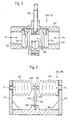
- Such a differential pressure gauge has, as shown in Fig. 3, a cylindrical housing 50.
- the housing 50 has openings 51 and 52 at both sides thereof. Pressures P1 and P2 on the two sides of the orifice 29 (30) are applied to the two sides of the housing 50 through the openings 51 and 52. Pressure-receiving pistons 53 and 54 are placed inside the openings 51 and 52, respectively.
- the pressure-receiving pistons 53 and 54 are each sealed at the outer peripheral portion thereof, and a transducer 55 is placed in the housing 50 in such a manner as to be sandwiched between the pressure-receiving pistons 53 and 54.
- the transducer 55 is a high response type transducer formed from a piezoelectric ceramic material to convert a pressure into an electric signal. The output of the transducer 55 is taken out through a cable 56.
- the transducer 55 detects a differential pressure between the pressures P 1 and P 2 on the two sides and transmits a detected signal to the computer 44 for control through the cable 56.
- Fig. 4 shows another form of the differential pressure gauges 39 and 40.
- the differential pressure gauge has a base 60, and support plates 61 and 62 are erectly attached to both sides of the base 60.
- Bellows 63 and 64 are rigidly secured to the opposing side surfaces of the support plates 61 and 62.
- Pressure members 65 and 66 are attached to the respective distal ends of the bellows 63 and 64.
- the pressure members 65 and 66 are placed to press the opposite sides of a plate spring 67.
- the plate spring 67 has a lower end portion thereof secured by a sandwiching portion 68 of the base 60.
- a resistant-wire strain gauge 69 is attached to each side surface of the plate spring 67.
- the pressures P 1 and P 2 on the two sides of the orifice 29 (31) are introduced into the bellows 63 and 64 of the differential pressure gauge 39 (40), and the bellows 63 and 64 extend or contract according to the introduced pressures.
- the pressure members 65 and 66 of the bellows 63 and 64 each press the plate spring 67, causing the plate spring 67 to be deflected.
- the deflection of the plate spring 67 is taken out through the resistant-wire strain gauges 69.
- the resistant-wire strain gauges 69 are connected into a bridge circuit, and the detected output is input to the computer 44 for control.
- exhaust gas generated by the operation of the engine 10 is discharged through the exhaust manifold 11 and the exhaust pipe 12.
- the exhaust pressure is regulated by the butterfly valve 13 for exhaust pressure regulation.
- the exhaust pulsation is reduced by the muffler 14.
- a part of exhaust gas passing through the exhaust pipe 15 is extracted through the sampling tube 30 and introduced into the mini-dilution tunnel 22.
- the exhaust gas is diluted with air introduced through the air introducing pipe 23.
- Air for dilution is sent from the dilution air supply pipe 25 to the air introducing pipe 23 by the air pump 24.
- the diluted exhaust gas is sampled by the sampling pump 32 and introduced to the NO x meter 33, where measurement of the amount of nitrogen oxides, that is, the NO x concentration Db, is carried out.
- the diluted exhaust gas is sucked by the sampling pump 35 to pass through the particulate filter 34. At this time, the amount of particulate matter trapped by the filter 34 is measured.
- the exhaust gas from the engine 10 before dilution is extracted directly from the exhaust pipe 15 through the thin pipe 37' at the outlet side of the muffler 14 and pretreated by the pretreatment device 37. Thereafter, the NO x concentration Db is measured by the NO x meter 38.
- the air pump 24, which is connected to the air introducing pipe 23, is driven to rotate by a motor 42.
- the number of revolutions of the motor 42 can be controlled by an inverter 43.
- the inverter 43 is controlled on the basis of a control command signal 43' from the computer 44.
- the exhaust gas flow rate Qt in the mini-dilution tunnel 22, the NO x concentration Dt in the mini-dilution tunnel 22, and the NO x concentration Db in the exhaust gas before dilution are input individually.
- the exhaust gas flow rate Qt in the mini-dilution tunnel 22 is measured by a method conformable to the method of measuring the flow rate in a dilution tunnel.
- the exhaust gas flow rate Qb in the exhaust pipe 15 is also measured as the sum of the intake air quantity and the fuel flow rate.
- the NO x concentration Dt in the mini-dilution tunnel 22 is measured with the NO x meter 33.
- the NO x concentration Db in the exhaust gas before dilution is measured with the NO x meter 38.
- the exhaust gas concentration split ratio Rc of the exhaust gas in the mini-dilution tunnel 22 of the exhaust gas measuring instrument in Fig. 1 is calculated from the ratio of the whole quantity of NO x in the exhaust gas emitted from the engine 10 to the whole quantity of NO x in the diluted gas in the mini-dilution tunnel 22 on the assumption that NO x is a tracer gas.
- the computer 44 controls the number of revolutions of the motor 42 through the inverter 43 to thereby control the number of revolutions of the air pump 24 so that the flow rate split ratio R obtained by the computer 44 coincides with a desired value. By doing so, it becomes possible to feedback-control the flow rate split ratio R of the exhaust gas.
- the pressure in the mini-dilution tunnel 22 changes, and this causes the flow rate split ratio to change. That is, if the number of revolutions of the pump 24 is increased to raise the pressure in the mini-dilution tunnel 22, it becomes difficult for the exhaust gas to enter the mini-dilution tunnel 22 through the sampling tube 30. Consequently, the flow rate split ratio R increases. If the number of revolutions of the pump 24 is reduced to lower the pressure in the mini-dilution tunnel 22, an increased amount of exhaust gas is introduced into the mini-dilution tunnel 22 through the sampling tube 30. As a result, the flow rate split ratio R reduces.
- the concentration split ratio Rc can be calculated by the computer 44 for control using Eq. (1)
- this method has the disadvantage that it requires several tens of seconds for the stabilization of the concentration of the tracer gas (in general, nitrogen oxides or carbonic acid gas), and therefore the response time is long. Accordingly, the method cannot be used during a transient operation of the engine.
- the tracer gas in general, nitrogen oxides or carbonic acid gas
- the calculation of the flow rate split ratio R based on Eq. (2) uses the differential pressure gauge 39 for the differential pressure between the two sides of the orifice 29 in the exhaust pipe 15 and the differential pressure gauge 40 for the differential pressure between the two sides of the orifice 31 in the sampling tube 30, and has the feature that the response is very fast.
- the use of Eq. (2) enables the flow rate split ratio R to be obtained with high accuracy even during a transient operation of the engine.
- the method using Eq. (2) has the disadvantage that it is readily affected by the use for a long period of time, temperature changes, etc. because of the use of orifices. Therefore, the flow rate split ratio R based on Eq. (2) is obtained, and the flow rate split ratio is calibrated by using the concentration split ratio Rc expressed by Eq. (1). By doing so, it is possible to obtain a flow rate split ratio with high accuracy during a transient operation of the engine.
- the high response type differential pressure gauge 39 is installed between the two sides of the orifice 29 in the exhaust pipe 15, and the high response type differential pressure gauge 40 is installed between the two sides of the orifice 31 in the sampling tube 30.
- the exhaust gas flow rate in the exhaust pipe 15 is obtained by measuring the differential pressure between the two sides of the orifice 29 with the differential pressure gauge 39 and input to the computer 44.
- the pressures on the two sides of the orifice 31 in the sampling tube 30 are detected with the differential pressure gauge 40, and the detected output is input to the computer 44.
- the exhaust gas flow rate Qb in the exhaust pipe 15 and the exhaust gas flow rate Qs in the sampling tube 30 are measured on the basis of the outputs of the differential pressure gauges 39 and 40.
- the flow rate split ratio R which is the ratio between the two flow rates, is calculated by the computer 44 and output by a printer or a pen recorder.
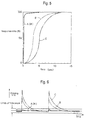
- the high response type differential pressure gauges 39 and 40 have characteristics represented by curve A. This shows that it is possible to obtain a response ratio more than ten times higher than curves B and C representing the characteristics of the conventional measuring methods.
- curve A shows that the flow rate split ratio R is measured in the transient operation mode of the engine by using the high response type differential pressure gauges 39 and 40
- the result of measurement falls within the limits of tolerance as shown by curve A in Fig. 6.
- Curves B and C in Fig. 6 show the results of measurement by the conventional measuring methods. Both the measurement results deviate from the limits of tolerance.
- the present invention enables measurement of the exhaust gas in the transient operation mode of the engine by a measuring instrument using the high response type differential pressure gauges 39 and 40 and the mini-dilution tunnel 22.
- the orifices 29 and 31 may change with time, resulting in a change in the flow rate coefficient in each of the orifices 29 and 31. Therefore, to minimize the error in the measured value due to such a change, the flow rate split ratio R is multiplied by a calibration coefficient k to obtain a calibrated flow rate coefficient k ⁇ R.
- the mini-dilution tunnel is installed.
- the high response type differential pressure gauge 39 is installed between the two sides of the orifice 29
- the high response type differential pressure gauge 40 is installed between the two sides of the orifice 31, thereby obtaining a flow rate split ratio in the transient operation mode of the engine.
- the amount of emission of exhaust gas components can be measured.
- an exhaust gas measuring instrument using a mini-dilution tunnel for the steady state operation mode can be changed to an exhaust gas measuring instrument for the transient operation mode.
Landscapes
- General Physics & Mathematics (AREA)
- Physics & Mathematics (AREA)
- Life Sciences & Earth Sciences (AREA)
- Health & Medical Sciences (AREA)
- Chemical & Material Sciences (AREA)
- Engineering & Computer Science (AREA)
- Fluid Mechanics (AREA)
- General Health & Medical Sciences (AREA)
- Analytical Chemistry (AREA)
- Biochemistry (AREA)
- Immunology (AREA)
- Pathology (AREA)
- Biomedical Technology (AREA)
- Molecular Biology (AREA)
- Food Science & Technology (AREA)
- Medicinal Chemistry (AREA)
- Combustion & Propulsion (AREA)
- Sampling And Sample Adjustment (AREA)
- Measuring Volume Flow (AREA)
Description
Claims (12)
- An exhaust gas measuring instrument comprising:characterized in thata mini-dilution tunnel (22) in which a part of an exhaust gas in an exhaust pipe (15) of an engine is introduced through an sampling tube (30) and diluted with air;measuring means (33) for measuring a specific component in the exhaust gas diluted in the mini-dilution tunnel (22);an extracted gas flow meter (40) which measures an exhaust gas flow rate (Qs) in said sampling tube (30);a bypassed gas flow meter (39) which measures an exhaust gas flow rate (Qb) in said exhaust pipe (15); andarithmetic means (44) for obtaining a flow rate split ratio (R) by dividing the exhaust gas flow rate in the exhaust pipe which is obtained by the bypassed gas flow meter (39) by the exhaust gas flow rate in the sampling tube (30) which is obtained by the extracted gas flow meter (40),
the extracted gas flow meter (40) is a high response differential pressure type extracted gas flow meter (40), the bypassed gas flow meter (39) is a high response differential pressure type bypassed gas flow meter (39), and the instrument further comprises means for obtaining a calibration coefficient (k) of the flow rate split ratio and means for obtaining a calibrated flow rate split ratio (k · R) by multiplying the flow rate split ratio by said calibration coefficient in a transient operation mode of the engine,
wherein the means for obtaining said calibration coefficient (k) comprises:wherein said arithmetic means (44) is configured to calculate:measuring means (38) for measuring a concentration (Db) of a specific substance in the exhaust gas in the exhaust pipe (15) during a steady state operation of the engine;means for measuring a diluted exhaust gas flow rate (Qt) in the mini-dilution tunnel (22); andmeasuring means (33) for measuring a concentration (Dt) of the specific substance in the exhaust gas diluted in the mini-dilution tunnel (22),and wherein said calibration coefficient (k) is obtained by dividing the concentration split ration (Rc) by the flow rate split ratio (R).a whole quantity (Qb · Db) of the specific substance in the exhaust pipe by multiplying the exhaust gas flow rate (Qb) in the exhaust pipe by the concentration of the specific substance in the exhaust gas in the exhaust pipe (15);a whole quantity (Qt · Dt) of the specific substance in the mini-dilution tunnel by multiplying the diluted exhaust gas flow rate in the mini-dilution tunnel (22) by the concentration of the specific substance in the exhaust gas diluted in the mini-dilution tunnel (22); anda concentration split ratio (Rc) by dividing the whole quantity of the specific substance in the exhaust pipe (15) by the whole quantity of the specific substance in the mini-dilution tunnel (22), - The exhaust gas measuring instrument according to claim 1, wherein said specific substance is nitrogen oxides.
- The exhaust gas measuring instrument according to claim 1 or 2, wherein the high response differential pressure type extracted gas flow meter has a sample orifice (31) installed in the sampling tube (30), and a differential pressure gauge (40) which detects a pressure difference between two sides of the sample orifice (31) produced by the exhaust gas passing through the sample orifice.
- The exhaust gas measuring instrument according to claim 3, wherein the differential pressure gauge (40), which detects a pressure difference at the sample orifice (31) has a first and second pressure-receiving piston (53, 54) and a transducer (55) placed between the two pressure-receiving pistons (53, 54) to convert a pressure into an electric signal, wherein a pressure on one side of the sample orifice (31) and a pressure on the other side of the sample orifice (31) are applied to the first and second pressure-receiving pistons, respectively, whereby a pressure difference produced at the sample orifice (31) is converted into an electric signal.
- The exhaust gas measuring instrument according to claim 3, wherein the differential pressure gauge (40), which detects a pressure difference at the sample orifice (31), has a first and second bellow (63, 64) and a resistant-wire strain gauge (69) which converts deformation of a plate spring (67), which is placed between the two bellows, into an electric signal, wherein a pressure on one side of the sample orifice (31) and a pressure on the other side of the sample orifice are applied to the first and second bellows, respectively, whereby a pressure difference produced at the sample orifice (31) is converted into an electric signal.
- The exhaust gas measuring instrument according to claim 1 or 2, wherein the high response differential pressure type bypassed gas flow meter has a bypass orifice (29) installed in the exhaust pipe (15), and a differential pressure gauge (39) which detects a pressure difference between two sides of the bypass orifice (29) produced by the exhaust gas passing through the bypass orifice.
- The exhaust gas measuring instrument according to claim 6, wherein the differential pressure gauge (39), which detects a pressure difference at the bypass orifice (29), has a first and second pressure-receiving piston and a transducer placed between the two pressure-receiving pistons to convert a pressure into an electric signal, wherein a pressure on one side of the bypass orifice and a pressure on the other side of the bypass orifice are applied to the first and second pressure-receiving pistons, respectively, whereby a pressure difference at the bypass orifice (29) is converted into an electric signal.
- The exhaust gas measuring instrument according to claim 6, wherein the differential pressure gauge (39), which detects a pressure difference at the bypass orifice (29), has a first and second bellows (63, 64) and a resistant-wire strain gauge (69) which converts deformation of a plate spring (67), which is placed between the two bellows, into an electric signal, wherein a pressure on one side of the bypass orifice (29) and a pressure on the other side of the bypass orifice (29) are applied to the first and second bellows, respectively, whereby a pressure difference at the bypass orifice (29) is converted into an electric signal.
- The exhaust gas measuring instrument according to claim 1 or 2, wherein the high response differential pressure type bypassed gas flow meter (39) measures the exhaust gas flow rate (Qb) in the exhaust pipe (15) as a sum of an intake air quantity and a fuel flow rate.
- The exhaust gas measuring instrument according to claim 1 or 2, wherein the high response differential pressure type bypassed gas flow meter (39), which measures the exhaust gas flow rate in said exhaust pipe (15), measures a flow rate of exhaust gas remaining after a part of exhaust gas has been extracted through said sampling tube (30).
- The exhaust gas measuring instrument according to claim 1 or 2, wherein the mini-dilution tunnel (22) has an air pump (24) which supplies air into the mini-dilution tunnel, and a blower (28) which discharges the exhaust gas diluted in the mini-dilution tunnel.
- The exhaust gas measuring instrument according to claim 11, wherein said blower (28) is rotated at a constant speed, and a number of revolutions of said air pump (24) is controlled, whereby the flow rate split ration (R) is feedback-controlled.
Applications Claiming Priority (3)
| Application Number | Priority Date | Filing Date | Title |
|---|---|---|---|
| JP27711196A JP3285313B2 (en) | 1996-09-27 | 1996-09-27 | Exhaust gas measurement device |
| JP27711196 | 1996-09-27 | ||
| PCT/JP1997/003289 WO1998013680A1 (en) | 1996-09-27 | 1997-09-18 | Exhaust gas measuring instrument |
Publications (3)
| Publication Number | Publication Date |
|---|---|
| EP0928962A1 EP0928962A1 (en) | 1999-07-14 |
| EP0928962A4 EP0928962A4 (en) | 2004-06-16 |
| EP0928962B1 true EP0928962B1 (en) | 2005-11-16 |
Family
ID=17578945
Family Applications (1)
| Application Number | Title | Priority Date | Filing Date |
|---|---|---|---|
| EP97940407A Expired - Lifetime EP0928962B1 (en) | 1996-09-27 | 1997-09-18 | Exhaust gas measuring instrument |
Country Status (7)
| Country | Link |
|---|---|
| US (1) | US6460400B1 (en) |
| EP (1) | EP0928962B1 (en) |
| JP (1) | JP3285313B2 (en) |
| KR (1) | KR100495981B1 (en) |
| CN (1) | CN1172174C (en) |
| DE (1) | DE69734664T2 (en) |
| WO (1) | WO1998013680A1 (en) |
Families Citing this family (38)
| Publication number | Priority date | Publication date | Assignee | Title |
|---|---|---|---|---|
| JP3285313B2 (en) | 1996-09-27 | 2002-05-27 | 日野自動車株式会社 | Exhaust gas measurement device |
| DE69917837T2 (en) * | 1998-07-17 | 2005-06-23 | Horiba Ltd. | Device for regulating the flow of a gas |
| JP2001249065A (en) * | 1999-12-28 | 2001-09-14 | Ono Sokki Co Ltd | Exhaust gas dilution device |
| ATE330221T1 (en) * | 2000-05-25 | 2006-07-15 | Her Majesty The Queen In The R | DEVICE AND METHOD FOR EMISSION SAMPLING |
| DE10112138A1 (en) * | 2001-03-14 | 2002-09-19 | Bosch Gmbh Robert | Method and device for monitoring a signal |
| US6615677B2 (en) * | 2001-07-10 | 2003-09-09 | Caterpillar Inc | Method for controlling dilution air |
| US7404340B2 (en) * | 2001-07-10 | 2008-07-29 | Caterpillar Inc. | Exhaust gas particulate measuring system |
| JP2004150864A (en) * | 2002-10-29 | 2004-05-27 | Toyota Motor Corp | Exhaust treatment device |
| US6945123B1 (en) * | 2004-06-28 | 2005-09-20 | The General Electric Company | Gas flow sensor having redundant flow sensing capability |
| US7201071B2 (en) * | 2005-02-11 | 2007-04-10 | Horiba, Ltd. | Wide range continuous diluter |
| US7389703B2 (en) * | 2005-09-29 | 2008-06-24 | Horiba Instruments, Inc. | Sampler for engine exhaust dilution |
| US7299690B2 (en) * | 2006-04-26 | 2007-11-27 | Caterpillar Inc. | Particulate sampling system and method |
| US8181543B2 (en) | 2006-09-15 | 2012-05-22 | Avl North America Inc. | CVS system sample water vapor management |
| US7565846B2 (en) * | 2006-10-11 | 2009-07-28 | Avl North America Inc. | Particulate sampler and dilution gas flow device arrangement for an exhaust sampling system |
| GR1006900B (en) * | 2007-02-14 | 2010-07-21 | Ζησης Σαμαρας | Diluter for exhaust gas sampling and method therefor. |
| JP4982720B2 (en) * | 2007-05-17 | 2012-07-25 | 一般社団法人日本ガス協会 | Sampling apparatus and sampling method |
| US8256307B2 (en) * | 2008-10-24 | 2012-09-04 | Caterpillar Inc. | Particulate sampling system and method of reducing oversampling during transients |
| US8104555B2 (en) * | 2008-10-30 | 2012-01-31 | Ford Global Technologies, Llc | Electro-mechanical pump for an automatic transmission |
| DE102010001645B4 (en) * | 2010-02-05 | 2023-11-23 | Endress + Hauser Flowtec Ag | Use of a flow measuring device and measuring system to determine a mass flow rate of a medium |
| DE102010027983B4 (en) * | 2010-04-20 | 2022-03-10 | Robert Bosch Gmbh | Method for operating an internal combustion engine for adjusting an exhaust gas probe |
| US8495922B1 (en) * | 2010-07-07 | 2013-07-30 | The United States Of America As Represented By The Secretary Of The Navy | Sampling system for ground level aircraft engine particle matter (PM) emission measurement |
| JP5492001B2 (en) * | 2010-07-23 | 2014-05-14 | 株式会社堀場製作所 | Exhaust gas analysis system |
| KR101246834B1 (en) * | 2011-06-28 | 2013-03-28 | 주식회사 씨앤포이엔지 | Apparatus for Sampling and Measuring Particulate Matter from Exhaust Gases |
| US9777637B2 (en) | 2012-03-08 | 2017-10-03 | General Electric Company | Gas turbine fuel flow measurement using inert gas |
| CN102607658B (en) * | 2012-03-08 | 2013-09-18 | 北京航空航天大学 | Method for measuring gas flow in complicated structure channel based on concentration method |
| US9297726B2 (en) | 2012-05-23 | 2016-03-29 | Avl Test Systems, Inc. | Exhaust sampling system and method for water vapor management |
| CN104380077B (en) | 2012-05-29 | 2018-03-27 | Avl测试系统公司 | Intelligent bag for exhaust gas sampling system is filled |
| US9279406B2 (en) | 2012-06-22 | 2016-03-08 | Illinois Tool Works, Inc. | System and method for analyzing carbon build up in an engine |
| JP5912981B2 (en) * | 2012-08-06 | 2016-04-27 | 株式会社堀場製作所 | Exhaust gas dilution device and PM measurement system |
| US10030568B2 (en) * | 2014-03-27 | 2018-07-24 | Dwight Eric STORY | Exhaust system integrity tester |
| CN104931650B (en) * | 2015-05-22 | 2017-01-04 | 江苏大学 | A kind of method measuring fluidics sprinkler gas content |
| CN105067493B (en) * | 2015-09-07 | 2017-09-29 | 常熟市矿山机电器材有限公司 | Flue dust concentration on-line measurement system and measuring apparatus and On-line Measuring Method |
| JP2018115997A (en) * | 2017-01-19 | 2018-07-26 | 株式会社堀場製作所 | Exhaust gas flow rate measurement unit and exhaust gas analyzer |
| JP7009083B2 (en) * | 2017-05-24 | 2022-01-25 | 株式会社堀場製作所 | Exhaust gas analyzer and exhaust gas analysis method |
| CN108008082B (en) * | 2017-12-21 | 2023-11-10 | 中冶长天国际工程有限责任公司 | A salt-containing gas or SRG gas detection system, analysis tower system and salt-containing gas or SRG gas detection method |
| AT521017B1 (en) * | 2018-04-06 | 2019-10-15 | Avl List Gmbh | Method for calibrating a mass flow meter in a Constant Volume Sampling (CVS) exhaust analysis system |
| CN114392631B (en) * | 2022-01-17 | 2022-12-09 | 北京京仪自动化装备技术股份有限公司 | Exhaust gas treatment efficiency adjustment method and exhaust gas treatment equipment |
| CN114459958B (en) * | 2022-02-11 | 2023-07-21 | 华北电力大学(保定) | Device and method for rapid measurement of airflow characteristics |
Family Cites Families (17)
| Publication number | Priority date | Publication date | Assignee | Title |
|---|---|---|---|---|
| JPS509193B1 (en) * | 1970-12-28 | 1975-04-10 | ||
| JPS4949659A (en) * | 1972-09-13 | 1974-05-14 | ||
| JPS56118641A (en) * | 1980-02-22 | 1981-09-17 | Nippon Soken Inc | Fine particle discharge amount measuring apparatus for vehicle |
| JPH0170120U (en) * | 1987-10-27 | 1989-05-10 | ||
| JPH07104233B2 (en) * | 1987-11-18 | 1995-11-13 | 株式会社堀場製作所 | Gas sampling device |
| JPH01150838A (en) * | 1987-12-09 | 1989-06-13 | Toyota Motor Corp | Measuring instrument for grain-like substance in engine exhaust gas |
| JP2739491B2 (en) * | 1989-02-15 | 1998-04-15 | 日野自動車工業株式会社 | Exhaust gas measurement device |
| AT391556B (en) * | 1989-03-13 | 1990-10-25 | Avl Verbrennungskraft Messtech | METHOD AND DEVICE FOR THE CONTINUOUS REMOVAL OF A PARTIAL AMOUNT FROM A GAS FLOW |
| JP2811564B2 (en) * | 1990-01-24 | 1998-10-15 | 株式会社 堀場製作所 | Measuring device for soot particles in automobile exhaust gas |
| JP2979694B2 (en) * | 1991-03-20 | 1999-11-15 | 日野自動車工業株式会社 | Exhaust gas measurement device |
| US5187972A (en) * | 1992-01-17 | 1993-02-23 | Clean Air Engineering, Inc. | Gas monitor |
| US5456124A (en) * | 1994-03-28 | 1995-10-10 | Ford Motor Company | Probe for exhaust gas sampling |
| JP3322380B2 (en) | 1995-03-16 | 2002-09-09 | 日野自動車株式会社 | Exhaust gas measurement device |
| US5712433A (en) * | 1995-08-07 | 1998-01-27 | Mitsubishi Jidosha Kogyo Kabushiki Kaisha | Exhaust gas measuring apparatus |
| US5596154A (en) * | 1995-09-21 | 1997-01-21 | Enviroplan, Inc. | Dilution control method and apparatus |
| JP3334778B2 (en) | 1995-11-20 | 2002-10-15 | 日野自動車株式会社 | Exhaust gas measurement device |
| JP3285313B2 (en) | 1996-09-27 | 2002-05-27 | 日野自動車株式会社 | Exhaust gas measurement device |
-
1996
- 1996-09-27 JP JP27711196A patent/JP3285313B2/en not_active Expired - Fee Related
-
1997
- 1997-09-18 KR KR10-1999-7002566A patent/KR100495981B1/en not_active Expired - Fee Related
- 1997-09-18 DE DE69734664T patent/DE69734664T2/en not_active Expired - Fee Related
- 1997-09-18 US US09/269,240 patent/US6460400B1/en not_active Expired - Fee Related
- 1997-09-18 EP EP97940407A patent/EP0928962B1/en not_active Expired - Lifetime
- 1997-09-18 CN CNB971990638A patent/CN1172174C/en not_active Expired - Fee Related
- 1997-09-18 WO PCT/JP1997/003289 patent/WO1998013680A1/en not_active Ceased
Also Published As
| Publication number | Publication date |
|---|---|
| US6460400B1 (en) | 2002-10-08 |
| KR20000048625A (en) | 2000-07-25 |
| CN1234113A (en) | 1999-11-03 |
| JP3285313B2 (en) | 2002-05-27 |
| JPH10104037A (en) | 1998-04-24 |
| EP0928962A4 (en) | 2004-06-16 |
| KR100495981B1 (en) | 2005-06-17 |
| CN1172174C (en) | 2004-10-20 |
| EP0928962A1 (en) | 1999-07-14 |
| DE69734664D1 (en) | 2005-12-22 |
| DE69734664T2 (en) | 2006-08-10 |
| WO1998013680A1 (en) | 1998-04-02 |
Similar Documents
| Publication | Publication Date | Title |
|---|---|---|
| US6460400B1 (en) | Exhaust gas measuring instrument | |
| EP1387999B1 (en) | Venturi flowmeter for use in an exhaust sampling apparatus | |
| US6200819B1 (en) | Method and apparatus for providing diluent gas to exhaust emission analyzer | |
| US5337595A (en) | Subsonic venturi proportional and isokinetic sampling methods and apparatus | |
| US5846831A (en) | Methods and systems for controlling flow of a diluted sample and determining pollutants based on water content in engine exhaust emissions | |
| US4586367A (en) | Proportional exhaust sampler and control means | |
| US4660408A (en) | Proportional exhaust sampler system and control means | |
| JP2835552B2 (en) | Exhaust sampler and its control means | |
| US4823591A (en) | Calibration method for exhaust mass flow measuring system | |
| US6973818B2 (en) | Exhaust volume measurement device | |
| EP1793210A2 (en) | Emission flow rate measuring method and apparatus | |
| US7204134B2 (en) | Engine suction air flow rate measuring device | |
| Stone et al. | Non-linear and unsteady flow analysis of flow in a viscous flowmeter | |
| US7555928B2 (en) | Exhaust volume measurement device | |
| JP2739491B2 (en) | Exhaust gas measurement device | |
| KR970048056A (en) | Exhaust gas velocity measurement and exhaust port tuning tester | |
| JPH01155235A (en) | Apparatus for measuring granular substance in exhaust gas |
Legal Events
| Date | Code | Title | Description |
|---|---|---|---|
| PUAI | Public reference made under article 153(3) epc to a published international application that has entered the european phase |
Free format text: ORIGINAL CODE: 0009012 |
|
| 17P | Request for examination filed |
Effective date: 19990415 |
|
| AK | Designated contracting states |
Kind code of ref document: A1 Designated state(s): DE FR GB IT SE |
|
| A4 | Supplementary search report drawn up and despatched |
Effective date: 20040504 |
|
| 17Q | First examination report despatched |
Effective date: 20040929 |
|
| GRAP | Despatch of communication of intention to grant a patent |
Free format text: ORIGINAL CODE: EPIDOSNIGR1 |
|
| GRAS | Grant fee paid |
Free format text: ORIGINAL CODE: EPIDOSNIGR3 |
|
| GRAA | (expected) grant |
Free format text: ORIGINAL CODE: 0009210 |
|
| AK | Designated contracting states |
Kind code of ref document: B1 Designated state(s): DE FR GB IT SE |
|
| PG25 | Lapsed in a contracting state [announced via postgrant information from national office to epo] |
Ref country code: IT Free format text: LAPSE BECAUSE OF FAILURE TO SUBMIT A TRANSLATION OF THE DESCRIPTION OR TO PAY THE FEE WITHIN THE PRESCRIBED TIME-LIMIT;WARNING: LAPSES OF ITALIAN PATENTS WITH EFFECTIVE DATE BEFORE 2007 MAY HAVE OCCURRED AT ANY TIME BEFORE 2007. THE CORRECT EFFECTIVE DATE MAY BE DIFFERENT FROM THE ONE RECORDED. Effective date: 20051116 |
|
| REG | Reference to a national code |
Ref country code: GB Ref legal event code: FG4D |
|
| REF | Corresponds to: |
Ref document number: 69734664 Country of ref document: DE Date of ref document: 20051222 Kind code of ref document: P |
|
| PG25 | Lapsed in a contracting state [announced via postgrant information from national office to epo] |
Ref country code: SE Free format text: LAPSE BECAUSE OF FAILURE TO SUBMIT A TRANSLATION OF THE DESCRIPTION OR TO PAY THE FEE WITHIN THE PRESCRIBED TIME-LIMIT Effective date: 20060216 |
|
| ET | Fr: translation filed | ||
| PLBE | No opposition filed within time limit |
Free format text: ORIGINAL CODE: 0009261 |
|
| STAA | Information on the status of an ep patent application or granted ep patent |
Free format text: STATUS: NO OPPOSITION FILED WITHIN TIME LIMIT |
|
| 26N | No opposition filed |
Effective date: 20060817 |
|
| PGFP | Annual fee paid to national office [announced via postgrant information from national office to epo] |
Ref country code: FR Payment date: 20080730 Year of fee payment: 12 |
|
| PGFP | Annual fee paid to national office [announced via postgrant information from national office to epo] |
Ref country code: GB Payment date: 20080904 Year of fee payment: 12 |
|
| PGFP | Annual fee paid to national office [announced via postgrant information from national office to epo] |
Ref country code: DE Payment date: 20080926 Year of fee payment: 12 |
|
| GBPC | Gb: european patent ceased through non-payment of renewal fee |
Effective date: 20090918 |
|
| REG | Reference to a national code |
Ref country code: FR Ref legal event code: ST Effective date: 20100531 |
|
| PG25 | Lapsed in a contracting state [announced via postgrant information from national office to epo] |
Ref country code: FR Free format text: LAPSE BECAUSE OF NON-PAYMENT OF DUE FEES Effective date: 20090930 Ref country code: DE Free format text: LAPSE BECAUSE OF NON-PAYMENT OF DUE FEES Effective date: 20100401 |
|
| PG25 | Lapsed in a contracting state [announced via postgrant information from national office to epo] |
Ref country code: GB Free format text: LAPSE BECAUSE OF NON-PAYMENT OF DUE FEES Effective date: 20090918 |