EP0928692B1 - Method for bonding a nozzle plate to an ink jet printhead - Google Patents
Method for bonding a nozzle plate to an ink jet printhead Download PDFInfo
- Publication number
- EP0928692B1 EP0928692B1 EP99100103A EP99100103A EP0928692B1 EP 0928692 B1 EP0928692 B1 EP 0928692B1 EP 99100103 A EP99100103 A EP 99100103A EP 99100103 A EP99100103 A EP 99100103A EP 0928692 B1 EP0928692 B1 EP 0928692B1
- Authority
- EP
- European Patent Office
- Prior art keywords
- nozzle plate
- nozzle
- printhead
- holder
- face
- Prior art date
- Legal status (The legal status is an assumption and is not a legal conclusion. Google has not performed a legal analysis and makes no representation as to the accuracy of the status listed.)
- Expired - Lifetime
Links
- 238000000034 method Methods 0.000 title claims description 15
- 239000012790 adhesive layer Substances 0.000 claims description 8
- 229920001187 thermosetting polymer Polymers 0.000 claims description 3
- 230000013011 mating Effects 0.000 claims description 2
- 229920006254 polymer film Polymers 0.000 claims description 2
- 239000000853 adhesive Substances 0.000 description 3
- 230000001070 adhesive effect Effects 0.000 description 3
- 238000009825 accumulation Methods 0.000 description 1
- 230000002411 adverse Effects 0.000 description 1
- 230000003993 interaction Effects 0.000 description 1
- 238000000608 laser ablation Methods 0.000 description 1
- 239000000463 material Substances 0.000 description 1
- 230000003287 optical effect Effects 0.000 description 1
- 230000005855 radiation Effects 0.000 description 1
- 238000009736 wetting Methods 0.000 description 1
Images



Classifications
-
- B—PERFORMING OPERATIONS; TRANSPORTING
- B41—PRINTING; LINING MACHINES; TYPEWRITERS; STAMPS
- B41J—TYPEWRITERS; SELECTIVE PRINTING MECHANISMS, i.e. MECHANISMS PRINTING OTHERWISE THAN FROM A FORME; CORRECTION OF TYPOGRAPHICAL ERRORS
- B41J2/00—Typewriters or selective printing mechanisms characterised by the printing or marking process for which they are designed
- B41J2/005—Typewriters or selective printing mechanisms characterised by the printing or marking process for which they are designed characterised by bringing liquid or particles selectively into contact with a printing material
- B41J2/01—Ink jet
- B41J2/135—Nozzles
- B41J2/16—Production of nozzles
-
- B—PERFORMING OPERATIONS; TRANSPORTING
- B41—PRINTING; LINING MACHINES; TYPEWRITERS; STAMPS
- B41J—TYPEWRITERS; SELECTIVE PRINTING MECHANISMS, i.e. MECHANISMS PRINTING OTHERWISE THAN FROM A FORME; CORRECTION OF TYPOGRAPHICAL ERRORS
- B41J2/00—Typewriters or selective printing mechanisms characterised by the printing or marking process for which they are designed
- B41J2/005—Typewriters or selective printing mechanisms characterised by the printing or marking process for which they are designed characterised by bringing liquid or particles selectively into contact with a printing material
- B41J2/01—Ink jet
- B41J2/135—Nozzles
- B41J2/16—Production of nozzles
- B41J2/162—Manufacturing of the nozzle plates
-
- B—PERFORMING OPERATIONS; TRANSPORTING
- B41—PRINTING; LINING MACHINES; TYPEWRITERS; STAMPS
- B41J—TYPEWRITERS; SELECTIVE PRINTING MECHANISMS, i.e. MECHANISMS PRINTING OTHERWISE THAN FROM A FORME; CORRECTION OF TYPOGRAPHICAL ERRORS
- B41J2/00—Typewriters or selective printing mechanisms characterised by the printing or marking process for which they are designed
- B41J2/005—Typewriters or selective printing mechanisms characterised by the printing or marking process for which they are designed characterised by bringing liquid or particles selectively into contact with a printing material
- B41J2/01—Ink jet
- B41J2/135—Nozzles
- B41J2/16—Production of nozzles
- B41J2/1621—Manufacturing processes
- B41J2/1623—Manufacturing processes bonding and adhesion
-
- B—PERFORMING OPERATIONS; TRANSPORTING
- B41—PRINTING; LINING MACHINES; TYPEWRITERS; STAMPS
- B41J—TYPEWRITERS; SELECTIVE PRINTING MECHANISMS, i.e. MECHANISMS PRINTING OTHERWISE THAN FROM A FORME; CORRECTION OF TYPOGRAPHICAL ERRORS
- B41J2/00—Typewriters or selective printing mechanisms characterised by the printing or marking process for which they are designed
- B41J2/005—Typewriters or selective printing mechanisms characterised by the printing or marking process for which they are designed characterised by bringing liquid or particles selectively into contact with a printing material
- B41J2/01—Ink jet
- B41J2/135—Nozzles
- B41J2/16—Production of nozzles
- B41J2/1621—Manufacturing processes
- B41J2/1632—Manufacturing processes machining
- B41J2/1634—Manufacturing processes machining laser machining
-
- B—PERFORMING OPERATIONS; TRANSPORTING
- B41—PRINTING; LINING MACHINES; TYPEWRITERS; STAMPS
- B41J—TYPEWRITERS; SELECTIVE PRINTING MECHANISMS, i.e. MECHANISMS PRINTING OTHERWISE THAN FROM A FORME; CORRECTION OF TYPOGRAPHICAL ERRORS
- B41J2/00—Typewriters or selective printing mechanisms characterised by the printing or marking process for which they are designed
- B41J2/005—Typewriters or selective printing mechanisms characterised by the printing or marking process for which they are designed characterised by bringing liquid or particles selectively into contact with a printing material
- B41J2/01—Ink jet
- B41J2/135—Nozzles
- B41J2/14—Structure thereof only for on-demand ink jet heads
- B41J2002/14362—Assembling elements of heads
-
- B—PERFORMING OPERATIONS; TRANSPORTING
- B41—PRINTING; LINING MACHINES; TYPEWRITERS; STAMPS
- B41J—TYPEWRITERS; SELECTIVE PRINTING MECHANISMS, i.e. MECHANISMS PRINTING OTHERWISE THAN FROM A FORME; CORRECTION OF TYPOGRAPHICAL ERRORS
- B41J2/00—Typewriters or selective printing mechanisms characterised by the printing or marking process for which they are designed
- B41J2/005—Typewriters or selective printing mechanisms characterised by the printing or marking process for which they are designed characterised by bringing liquid or particles selectively into contact with a printing material
- B41J2/01—Ink jet
- B41J2/135—Nozzles
- B41J2/14—Structure thereof only for on-demand ink jet heads
- B41J2002/14379—Edge shooter
-
- Y—GENERAL TAGGING OF NEW TECHNOLOGICAL DEVELOPMENTS; GENERAL TAGGING OF CROSS-SECTIONAL TECHNOLOGIES SPANNING OVER SEVERAL SECTIONS OF THE IPC; TECHNICAL SUBJECTS COVERED BY FORMER USPC CROSS-REFERENCE ART COLLECTIONS [XRACs] AND DIGESTS
- Y10—TECHNICAL SUBJECTS COVERED BY FORMER USPC
- Y10T—TECHNICAL SUBJECTS COVERED BY FORMER US CLASSIFICATION
- Y10T29/00—Metal working
- Y10T29/42—Piezoelectric device making
-
- Y—GENERAL TAGGING OF NEW TECHNOLOGICAL DEVELOPMENTS; GENERAL TAGGING OF CROSS-SECTIONAL TECHNOLOGIES SPANNING OVER SEVERAL SECTIONS OF THE IPC; TECHNICAL SUBJECTS COVERED BY FORMER USPC CROSS-REFERENCE ART COLLECTIONS [XRACs] AND DIGESTS
- Y10—TECHNICAL SUBJECTS COVERED BY FORMER USPC
- Y10T—TECHNICAL SUBJECTS COVERED BY FORMER US CLASSIFICATION
- Y10T29/00—Metal working
- Y10T29/49—Method of mechanical manufacture
- Y10T29/49401—Fluid pattern dispersing device making, e.g., ink jet
-
- Y—GENERAL TAGGING OF NEW TECHNOLOGICAL DEVELOPMENTS; GENERAL TAGGING OF CROSS-SECTIONAL TECHNOLOGIES SPANNING OVER SEVERAL SECTIONS OF THE IPC; TECHNICAL SUBJECTS COVERED BY FORMER USPC CROSS-REFERENCE ART COLLECTIONS [XRACs] AND DIGESTS
- Y10—TECHNICAL SUBJECTS COVERED BY FORMER USPC
- Y10T—TECHNICAL SUBJECTS COVERED BY FORMER US CLASSIFICATION
- Y10T29/00—Metal working
- Y10T29/49—Method of mechanical manufacture
- Y10T29/49826—Assembling or joining
- Y10T29/49895—Associating parts by use of aligning means [e.g., use of a drift pin or a "fixture"]
-
- Y—GENERAL TAGGING OF NEW TECHNOLOGICAL DEVELOPMENTS; GENERAL TAGGING OF CROSS-SECTIONAL TECHNOLOGIES SPANNING OVER SEVERAL SECTIONS OF THE IPC; TECHNICAL SUBJECTS COVERED BY FORMER USPC CROSS-REFERENCE ART COLLECTIONS [XRACs] AND DIGESTS
- Y10—TECHNICAL SUBJECTS COVERED BY FORMER USPC
- Y10T—TECHNICAL SUBJECTS COVERED BY FORMER US CLASSIFICATION
- Y10T29/00—Metal working
- Y10T29/53—Means to assemble or disassemble
- Y10T29/5313—Means to assemble electrical device
- Y10T29/53191—Means to apply vacuum directly to position or hold work part
Definitions
- the present invention relates generally to ink jet printheads and, more particularly, to an improved method and apparatus for bonding a nozzle plate to the nozzle face of an ink jet printhead.
- a major source of ink jet misdirection is associated with improper wetting of the nozzle surface of the printhead which contains the array of nozzles; e.g., the nozzle face.
- One factor which adversely affects jet directional accuracy is the interaction of ink accumulating on the nozzle face of the printhead array with the ejected droplets.
- a preferred technique is to bond a thin polymeric film (referred to as a nozzle plate) to the printhead nozzle face and, using a mask, form holes through the film connecting to the channels of the printhead. This technique is disclosed, for example, in U.S. Patents 5,434,607 and 5,493,320.
- a preferred method for forming the holes in a nozzle plate is by laser ablation.
- a UV excimer laser 2 emits a beam of radiation which is directed through holes 4 of a mask 6 to a portion of a thin polymeric film 8, a portion of which will form a nozzle plate 10.
- the energy level and pulse repetition rate of the laser are controlled to form nozzle holes 12 in plate 10.
- Plate 10 is then aligned with nozzles 14 formed on the front face 16 of a printhead 18.
- the nozzle plate must be securely bonded to the nozzle face of the printhead and must be accurately aligned so that the holes formed in the nozzle plate are in precise alignment with the nozzle orifices; e.g., that holes 12 are aligned with holes 14. There is a continuing need for an accurate bonding and alignment process.
- the present invention relates to a method for bonding a nozzle plate to a printhead nozzle face at a bonding station which includes a nozzle plate holder having a concave bottom surface, the nozzle plate holder positioned opposite a printhead holder, and including the steps of:
- the invention also relates to an apparatus for bonding nozzle plates through the printhead nozzle face comprising:
- FIG. 2 shows a side view of an apparatus for aligning a previously formed nozzle plate to a printhead nozzle face and for bonding the plate to the nozzle face after a critical alignment position has been secured.
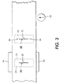
- FIG. 3 shows a top view of a portion of FIG. 2.
- the holder 24, in a preferred embodiment, is heated by a heater 27.
- the printhead is held so that nozzle face 26, with a plurality of nozzle 28 forming a nozzle array 30 along its length, is aligned in a horizontal plane.
- Printhead holder 24 can be moved along rotational axis 32 and translated over axis 34 for purposes described below.
- nozzle plate holder 36 Located above, and opposite to holder 24, is nozzle plate holder 36 having a concave bottom surface attached to an upper fixture 38.
- Fixture 38 movable in a vertical direction has an air passageway 40 connected by flexible tube 41 to a vacuum source 42.
- Curved nozzle plate holder 36 having a concave bottom surface with a radius of curvature r, is held in vacuum contact with the bottom of fixture 38.
- Holder 36 as shown in bottom view of FIG. 4, has a pair of alignment pins 44 projecting therefrom, a centrally located elliptical aperture 46 and a pair of slots 48 on either side of the aperture.
- a vacuum is applied to slots 48 through holes (not shown) formed in the bottom of fixture 38.
- Holder 36 can be rotated along a rotational axis 32' and translational axis 34'.
- a thin polymer film 50 having a thermosetting adhesive layer 51 applied to the bottom surface, is unrolled from film supply roll 52 and passes through a nozzle plate forming station 54 and into the bonding and alignment station 25, passing through a curing station 58, and onto the take-up roll 60 driven in a counter-clockwise direction by conventional motor means.
- Supply roll 52 and tape-up roll 60 are aligned in substantially the same horizontal plane.
- a section of the film 50 which will be formed into a nozzle plate, is laser ablated by, for example, the techniques shown in the aforementioned application, to form nozzle and alignment holes.
- a nozzle plate 62 is shown in FIG. 3 following passage through station 54. Alignment holes 64 and slot 66 have been formed above and below a nozzle hole array 68 comprising nozzle holes 70 which are to be aligned with nozzles 28 on nozzle array 30, followed by bonding of the nozzle plate to the printhead face 26.
- the nozzle plates may be formed at another location and rolled onto supply roll 52.
- station 54 is not required.
- a gross alignment of the nozzle plate hole array 68 to the printhead nozzle array 30 in the direction perpendicular to array 30 is made. This is accomplished by first moving a nozzle plate 62 into station 25 and referencing hole 64 and slot 66 formed in the nozzle plate to pins 44 in holder 36. This alignment insures that the nozzle hole array 68 is located on a line perpendicular to the holder radius. The gross alignment is then made by adjustments along axis 34 and 34' of the printhead holder and nozzle holder, respectively.
- fixture 38 and holder 36 are lowered bringing the curved surface of holder 36 into contact with the film.
- a portion of the film formed without adhesive is pushed downward into tangential contact with the surface of nozzle array 30.
- rotational adjustments are made along axis 32, 32' until white light interference fringes are observed at the desired contact point.
- the interference fringes are produced by conventional optical means.
- a final fine alignment is made of nozzles 28 to nozzle plate hole 70, directed primarily at alignment of the nozzle hole array 68 to nozzle array 30. This is accomplished by fine adjustments along the rotational axis 32, 32' and translation axis 34, 34'.
- the nozzle plate is fully lowered into tangential contact with the nozzle face. Because of the curvature of holder 36, the plate is also curved and acquires an increase in rigidity that allows firm downward pressure to be applied all along the contact areas as shown in FIG. 5. Once there is initial contact, the film 50 containing plate 62 continues to be lowered so as to bond to the entire surface of the printhead face (not specifically at the center near the array).
- the elliptical aperture 46 allows the film to flex so that, as the film continues to be lowered, it flattens along the tangent (see FIG. 5) allowing contact along the entire face.
- the thermal setting adhesive applied along the bottom surface of the film at station 56 wets the nozzle face 26 and begins to cure immediately since the printhead has been, and continues to be, preheated. After a few minutes, the vacuum is released and the film, with bonded printhead attached, moves to curing station 58 for additional and final curing of the adhesive. The printhead assembly can then be individually separated at this point by cutting out the printhead assembly leaving a film border to be taken up onto roll 60.
- the apparatus 20, shown in FIG. 2 can be fully automated so that a plurality of nozzle plates are formed in film 50 and bonded to a plurality of printheads.
Landscapes
- Engineering & Computer Science (AREA)
- Manufacturing & Machinery (AREA)
- Physics & Mathematics (AREA)
- Optics & Photonics (AREA)
- Particle Formation And Scattering Control In Inkjet Printers (AREA)
Description
- The present invention relates generally to ink jet printheads and, more particularly, to an improved method and apparatus for bonding a nozzle plate to the nozzle face of an ink jet printhead.
- A major source of ink jet misdirection is associated with improper wetting of the nozzle surface of the printhead which contains the array of nozzles; e.g., the nozzle face. One factor which adversely affects jet directional accuracy is the interaction of ink accumulating on the nozzle face of the printhead array with the ejected droplets.
- Various techniques have been used to reduce or eliminate the ink accumulation to improve directionality at the nozzle face. A preferred technique is to bond a thin polymeric film (referred to as a nozzle plate) to the printhead nozzle face and, using a mask, form holes through the film connecting to the channels of the printhead. This technique is disclosed, for example, in U.S. Patents 5,434,607 and 5,493,320.
- A preferred method for forming the holes in a nozzle plate is by laser ablation. For this technique, as shown in FIG. 1, a UV excimer laser 2 emits a beam of radiation which is directed through
holes 4 of amask 6 to a portion of a thinpolymeric film 8, a portion of which will form anozzle plate 10. The energy level and pulse repetition rate of the laser are controlled to formnozzle holes 12 inplate 10.Plate 10 is then aligned withnozzles 14 formed on thefront face 16 of aprinthead 18. - For all the above-cited prior art references, the nozzle plate must be securely bonded to the nozzle face of the printhead and must be accurately aligned so that the holes formed in the nozzle plate are in precise alignment with the nozzle orifices; e.g., that
holes 12 are aligned withholes 14. There is a continuing need for an accurate bonding and alignment process. - It is desirable to provide a method for bonding a nozzle plate to a printhead so that the nozzle plate apertures or holes are precisely aligned with the nozzle orifices of the printhead. This is accomplished, according to the invention, by securing the nozzle plate against a curved surface of a nozzle plate holder, thus, imparting curvature and rigidity to the nozzle plate. The nozzle plate is then tangentially aligned through the plane of the nozzle face. Once tangential contact is made, the nozzle plate is lowered into binding contact, with first order alignment accomplished by slots through the nozzle plate referenced to pins on the holder and film held in place with vacuum.
- More particularly, the present invention relates to a method for bonding a nozzle plate to a printhead nozzle face at a bonding station which includes a nozzle plate holder having a concave bottom surface, the nozzle plate holder positioned opposite a printhead holder, and including the steps of:
- forming a nozzle plate from a thin polymeric film having a thin adhesive layer on a bottom surface, the nozzle plate having a plurality of holes forming a linear array, and having further formed therethrough a plurality of alignment apertures,
- placing the nozzle plate into a bonding station,
- securing the plate to the curved bottom surface of the nozzle plate holder by vacuum means,
- aligning the nozzle plate by securing the alignment apertures of the nozzle plate over alignment pins on the nozzle plate holder curved bottom surface, thereby locating the linear array of holes in the nozzle plate on a line perpendicular to the curved bottom surface,
- seating a printhead in the printhead holder with a nozzle face having a nozzle array in an upward direction,
- providing a first, coarse alignment of the nozzle plate to the printhead face in a direction perpendicular to the nozzle array,
- making fine translational and rotational alignments of the nozzle plate holder and printhead holder so that the nozzle holes and the nozzle plate are precisely aligned with the nozzles of the printhead nozzle array,
- lowering the nozzle plate into tangential contact with the printhead face providing a rotational adjustment of the nozzle plate holder until the initial contact point is along the center of the nozzle array,
- applying further downward pressure to bond the nozzle plate to the printhead nozzle face and
- curing the bonded surface.
-
- The invention also relates to an apparatus for bonding nozzle plates through the printhead nozzle face comprising:
- a bonding station having a nozzle plate holder with a bottom surface having a radius of curvature and having alignment pins projecting therethrough, and having a central aperture formed therethrough,
- a printhead holder positioned opposite and beneath said nozzle plate holder, said printhead holder having seated thereon a printhead with a front nozzle face lying in a horizontal plane separated from said nozzle plate holder bottom surface, the nozzle face having a plurality of nozzles in a linear array,
- a nozzle plate formed in a thin polymeric film, the nozzle plate having alignment apertures aligned with a linear hole array formed therethrough and having a thermosetting adhesive layer formed on the bottom surface of said nozzle plate,
- means for securing the top surface of the nozzle plate to the bottom surface of the nozzle plate holder, aligning the nozzle plate to said bottom surface by mating said apertures to said alignment pins,
- means for producing translational and rotational alignment between said printhead holder and said nozzle plate holder whereby, when the nozzle plate holder, with the nozzle plate attached thereto, is lowered into contact with the nozzle face, the linear hole array in the nozzle plate is precisely aligned with the nozzle array of the printhead and
- means for curing the adhesive layer to create a permanent bond between the nozzle plate and the printhead nozzle face.
-
-
- FIG. 1 is a prior art exploded view of a laser ablated nozzle plate bonded to a printhead nozzle face.
- FIG. 2 is a side view of an apparatus for bonding a nozzle plate to a printhead nozzle face according to the invention.
- FIG. 3 is a partial top view of the FIG. 2 apparatus showing the printhead holder.
- FIG. 4 is a bottom view of the nozzle plate holder.
- FIG. 5 is a side view of the nozzle plate film being bonded to the printhead nozzle face.
-
- FIG. 2 shows a side view of an apparatus for aligning a previously formed nozzle plate to a printhead nozzle face and for bonding the plate to the nozzle face after a critical alignment position has been secured. FIG. 3 shows a top view of a portion of FIG. 2. An
ink jet printhead 22, which, in a preferred embodiment, is fabricated by the process disclosed in U.S. 4,638,337, is held in aprinthead holder 24 located in an alignment andbonding station 25. Theholder 24, in a preferred embodiment, is heated by aheater 27. The printhead is held so thatnozzle face 26, with a plurality ofnozzle 28 forming anozzle array 30 along its length, is aligned in a horizontal plane.Printhead holder 24 can be moved alongrotational axis 32 and translated overaxis 34 for purposes described below. - Located above, and opposite to
holder 24, isnozzle plate holder 36 having a concave bottom surface attached to anupper fixture 38.Fixture 38 movable in a vertical direction has anair passageway 40 connected byflexible tube 41 to avacuum source 42. Curvednozzle plate holder 36, having a concave bottom surface with a radius of curvature r, is held in vacuum contact with the bottom offixture 38.Holder 36, as shown in bottom view of FIG. 4, has a pair ofalignment pins 44 projecting therefrom, a centrally locatedelliptical aperture 46 and a pair ofslots 48 on either side of the aperture. A vacuum is applied toslots 48 through holes (not shown) formed in the bottom offixture 38.Holder 36 can be rotated along a rotational axis 32' and translational axis 34'. - Continuing with a description of FIGS. 2 and 3, a
thin polymer film 50, having a thermosettingadhesive layer 51 applied to the bottom surface, is unrolled fromfilm supply roll 52 and passes through a nozzleplate forming station 54 and into the bonding andalignment station 25, passing through acuring station 58, and onto the take-up roll 60 driven in a counter-clockwise direction by conventional motor means.Supply roll 52 and tape-uproll 60 are aligned in substantially the same horizontal plane. - At
station 54, a section of thefilm 50, which will be formed into a nozzle plate, is laser ablated by, for example, the techniques shown in the aforementioned application, to form nozzle and alignment holes. Anozzle plate 62 is shown in FIG. 3 following passage throughstation 54.Alignment holes 64 andslot 66 have been formed above and below anozzle hole array 68 comprisingnozzle holes 70 which are to be aligned withnozzles 28 onnozzle array 30, followed by bonding of the nozzle plate to theprinthead face 26. Alternately, the nozzle plates may be formed at another location and rolled ontosupply roll 52. For this embodiment,station 54 is not required. - Prior to a fine alignment and bonding step, a gross alignment of the nozzle
plate hole array 68 to theprinthead nozzle array 30 in the direction perpendicular toarray 30 is made. This is accomplished by first moving anozzle plate 62 intostation 25 and referencinghole 64 andslot 66 formed in the nozzle plate topins 44 inholder 36. This alignment insures that thenozzle hole array 68 is located on a line perpendicular to the holder radius. The gross alignment is then made by adjustments alongaxis 34 and 34' of the printhead holder and nozzle holder, respectively. - Following the gross adjustment,
fixture 38 andholder 36 are lowered bringing the curved surface ofholder 36 into contact with the film. A portion of the film formed without adhesive is pushed downward into tangential contact with the surface ofnozzle array 30. To insure that the initial tangential contact point is along the center ofarray 30 in a direction into the page, rotational adjustments are made alongaxis 32, 32' until white light interference fringes are observed at the desired contact point. The interference fringes are produced by conventional optical means. - Following the nozzle plate holder rotational adjustment, a final fine alignment is made of
nozzles 28 tonozzle plate hole 70, directed primarily at alignment of thenozzle hole array 68 tonozzle array 30. This is accomplished by fine adjustments along therotational axis 32, 32' andtranslation axis 34, 34'. Once this final alignment is complete, the nozzle plate is fully lowered into tangential contact with the nozzle face. Because of the curvature ofholder 36, the plate is also curved and acquires an increase in rigidity that allows firm downward pressure to be applied all along the contact areas as shown in FIG. 5. Once there is initial contact, thefilm 50 containingplate 62 continues to be lowered so as to bond to the entire surface of the printhead face (not specifically at the center near the array). This can be done because the film is not being held rigidly along the printhead nozzle face. Theelliptical aperture 46 allows the film to flex so that, as the film continues to be lowered, it flattens along the tangent (see FIG. 5) allowing contact along the entire face. - The thermal setting adhesive applied along the bottom surface of the film at station 56 wets the
nozzle face 26 and begins to cure immediately since the printhead has been, and continues to be, preheated. After a few minutes, the vacuum is released and the film, with bonded printhead attached, moves to curingstation 58 for additional and final curing of the adhesive. The printhead assembly can then be individually separated at this point by cutting out the printhead assembly leaving a film border to be taken up ontoroll 60. - It will be appreciated that the apparatus 20, shown in FIG. 2, can be fully automated so that a plurality of nozzle plates are formed in
film 50 and bonded to a plurality of printheads.
Claims (8)
- A method for bonding a nozzle plate to a printhead nozzle face at a bonding station which includes a nozzle plate holder having a concave bottom surface, the nozzle plate holder positioned opposite a printhead holder, and including the steps of:forming a nozzle plate from a thin polymeric film having a thin adhesive layer on a bottom surface, the nozzle plate having a plurality of holes forming a linear array, and having further formed therethrough a plurality of alignment apertures,placing the nozzle plate into a bonding station,securing the plate to the curved bottom surface of the nozzle plate holder by vacuum means,aligning the nozzle plate by securing the alignment apertures of the nozzle plate over alignment pins on the nozzle plate holder curved bottom surface, thereby locating the linear array of holes in the nozzle plate on a line perpendicular to the curved bottom surface,seating a printhead in the printhead holder with a nozzle face having a nozzle array in an upward direction,providing a first, coarse alignment of the nozzle plate to the printhead face in a direction perpendicular to the nozzle array,making fine translational and rotational alignments of the nozzle plate holder and printhead holder so that the nozzle holes and the nozzle plate are precisely aligned with the nozzles of the printhead nozzle array,lowering the nozzle plate into tangential contact with the printhead face providing a rotational adjustment of the nozzle plate holder until the initial contact point is along the center of the nozzle array,applying further downward pressure to bond the nozzle plate to the printhead nozzle face andcuring the bonded surface.
- The method of claim 1 wherein said printhead holder is heated thereby providing a component of the required curing.
- The method according to claim 1 or 2 wherein a plurality of nozzle plates are formed in a thin polymer film which is unrolled from a supply roll and taken up on a tape-up roll.
- An apparatus for bonding nozzle plates through the printhead nozzle face comprising:a bonding station having a nozzle plate holder with a bottom concave surface having a radius of curvature and having alignment pins projecting therethrough, and having a central aperture formed therethrough,a printhead holder positioned opposite and beneath said nozzle plate holder, said printhead holder having seated thereon a printhead with a front nozzle face separated from said nozzle plate holder bottom surface, the nozzle face having a plurality of nozzles in a linear array,a nozzle plate formed in a thin polymeric film at a nozzle plate forming station, the nozzle plate having alignment apertures aligned with a linear hole array formed therethrough and having a thermosetting adhesive layer formed on the bottom surface of said nozzle plate,means for securing the top surface of the nozzle plate to the bottom surface of the nozzle plate holder, aligning the nozzle plate to said bottom surface by mating said apertures to said alignment pins,means for producing translational and rotational alignment between said printhead holder and said nozzle plate holder whereby, when the nozzle plate holder, with the nozzle plate attached thereto, is lowered into contact with the nozzle face, the linear hole array in the nozzle plate is precisely aligned with the nozzle array of the printhead andmeans for curing the adhesive layer to create a permanent bond between the nozzle plate and the printhead nozzle face to form a printhead assembly comprising the printhead and the bonded nozzle plate.
- The apparatus according to claim 4 further including means for curing the adhesive layer at a curing station.
- The apparatus according to claim 4 or 5 wherein vacuum means are provided for securing the top surface of the nozzle plate to the bottom surface of the nozzle plate holder.
- The apparatus according to any of the claims 4 to 6 wherein said nozzle plate holder has an aperture through the center thereof which allows the nozzle plate to flex as it is being pressed into contact with the printhead nozzle face.
- The apparatus according to any of the claims 4 to 7 further including a film supply and a film take-up roll and means for moving said film from said take-up roll through said nozzle plate forming station, said bonding station and said curing station, onto said take-up roll.
Applications Claiming Priority (2)
| Application Number | Priority Date | Filing Date | Title |
|---|---|---|---|
| US09/004,259 US5950309A (en) | 1998-01-08 | 1998-01-08 | Method for bonding a nozzle plate to an ink jet printhead |
| US4259 | 1998-01-08 |
Publications (3)
| Publication Number | Publication Date |
|---|---|
| EP0928692A2 EP0928692A2 (en) | 1999-07-14 |
| EP0928692A3 EP0928692A3 (en) | 1999-12-01 |
| EP0928692B1 true EP0928692B1 (en) | 2001-10-10 |
Family
ID=21709927
Family Applications (1)
| Application Number | Title | Priority Date | Filing Date |
|---|---|---|---|
| EP99100103A Expired - Lifetime EP0928692B1 (en) | 1998-01-08 | 1999-01-04 | Method for bonding a nozzle plate to an ink jet printhead |
Country Status (4)
| Country | Link |
|---|---|
| US (1) | US5950309A (en) |
| EP (1) | EP0928692B1 (en) |
| JP (1) | JP4143198B2 (en) |
| DE (1) | DE69900337T2 (en) |
Families Citing this family (9)
| Publication number | Priority date | Publication date | Assignee | Title |
|---|---|---|---|---|
| US6841024B2 (en) * | 2002-10-24 | 2005-01-11 | Lexmark International, Inc. | Compensation plates and compliant members for laser welding a non-uniformly thick work piece including inkjet printheads with non-uniformly thick printhead lids |
| US6811250B2 (en) * | 2002-11-19 | 2004-11-02 | Lexmark International, Inc. | Ink conduit plugs for an inkjet printhead and methods of laser welding same |
| US6974207B2 (en) * | 2002-11-19 | 2005-12-13 | Lexmark International, Inc. | Laser welding methods and structures and control therefor including welded inkjet printheads |
| US20050206679A1 (en) * | 2003-07-03 | 2005-09-22 | Rio Rivas | Fluid ejection assembly |
| US20050099449A1 (en) * | 2003-11-07 | 2005-05-12 | Tim Frasure | Methods and structures for disassembling inkjet printhead components and control therefor |
| US7291226B2 (en) * | 2004-09-30 | 2007-11-06 | Lexmark International, Inc. | Progressive stencil printing |
| JP5223820B2 (en) * | 2009-08-21 | 2013-06-26 | コニカミノルタIj株式会社 | Inkjet head manufacturing method |
| US8684499B2 (en) | 2010-09-24 | 2014-04-01 | Xerox Corporation | Method for forming an aperture and actuator layer for an inkjet printhead |
| WO2020106295A1 (en) | 2018-11-21 | 2020-05-28 | Hewlett-Packard Development Company, L.P. | Curved fluid ejection devices |
Family Cites Families (19)
| Publication number | Priority date | Publication date | Assignee | Title |
|---|---|---|---|---|
| JPS61163863A (en) * | 1985-01-14 | 1986-07-24 | Nec Corp | Manufacture of head for ink jet printer |
| US4638337A (en) * | 1985-08-02 | 1987-01-20 | Xerox Corporation | Thermal ink jet printhead |
| US4999077A (en) * | 1989-08-31 | 1991-03-12 | Xerox Corporation | Method of fabricating full width scanning or imaging arrays from subunits |
| US4975143A (en) * | 1989-11-22 | 1990-12-04 | Xerox Corporation | Keyway alignment substrates |
| US5098503A (en) * | 1990-05-01 | 1992-03-24 | Xerox Corporation | Method of fabricating precision pagewidth assemblies of ink jet subunits |
| JP3351436B2 (en) * | 1991-08-21 | 2002-11-25 | セイコーエプソン株式会社 | Two-part adhesive sheet material having pores |
| US5285888A (en) * | 1991-09-25 | 1994-02-15 | Kabushiki Kaisha Toshiba | Parts mounting apparatus |
| US5467115A (en) * | 1992-04-02 | 1995-11-14 | Hewlett-Packard Company | Inkjet printhead formed to eliminate ink trajectory errors |
| US5297331A (en) * | 1992-04-03 | 1994-03-29 | Hewlett-Packard Company | Method for aligning a substrate with respect to orifices in an inkjet printhead |
| US5434607A (en) * | 1992-04-02 | 1995-07-18 | Hewlett-Packard Company | Attachment of nozzle plate to flexible circuit for facilitating assembly of printhead |
| US5623754A (en) * | 1992-10-01 | 1997-04-29 | Chick Machine Tool, Inc. | Apparatus for facilitating the detachment of an element from an object |
| US5408746A (en) * | 1993-04-30 | 1995-04-25 | Hewlett-Packard Company | Datum formation for improved alignment of multiple nozzle members in a printer |
| GB9316605D0 (en) * | 1993-08-10 | 1993-09-29 | Xaar Ltd | Droplet deposition apparatus and method of manufacture |
| GB9321786D0 (en) * | 1993-10-22 | 1993-12-15 | Xaar Ltd | Droplet deposition apparatus |
| JPH07299529A (en) * | 1994-05-02 | 1995-11-14 | Xerox Corp | Locating shape |
| US5546654A (en) * | 1994-08-29 | 1996-08-20 | General Electric Company | Vacuum fixture and method for fabricating electronic assemblies |
| US5493320A (en) * | 1994-09-26 | 1996-02-20 | Lexmark International, Inc. | Ink jet printing nozzle array bonded to a polymer ink barrier layer |
| AU691036B2 (en) * | 1994-10-31 | 1998-05-07 | Canon Kabushiki Kaisha | Manufacturing method of ink jet head, ink jet head manufactured by same and ink jet device having ink jet head |
| JP3179328B2 (en) * | 1996-02-07 | 2001-06-25 | シチズン時計株式会社 | Inkjet head |
-
1998
- 1998-01-08 US US09/004,259 patent/US5950309A/en not_active Expired - Lifetime
-
1999
- 1999-01-04 DE DE69900337T patent/DE69900337T2/en not_active Expired - Lifetime
- 1999-01-04 EP EP99100103A patent/EP0928692B1/en not_active Expired - Lifetime
- 1999-01-04 JP JP00003399A patent/JP4143198B2/en not_active Expired - Fee Related
Also Published As
| Publication number | Publication date |
|---|---|
| EP0928692A2 (en) | 1999-07-14 |
| DE69900337D1 (en) | 2001-11-15 |
| DE69900337T2 (en) | 2002-04-25 |
| JP4143198B2 (en) | 2008-09-03 |
| EP0928692A3 (en) | 1999-12-01 |
| US5950309A (en) | 1999-09-14 |
| JPH11245422A (en) | 1999-09-14 |
Similar Documents
| Publication | Publication Date | Title |
|---|---|---|
| US5855713A (en) | Method of making a multi-channel droplet deposition apparatus | |
| CA2084564C (en) | Nozzle member including ink flow channels | |
| EP0564101B1 (en) | Laser ablated nozzle member for inkjet printhead | |
| CA2084344C (en) | Structure and method for aligning a substrate with respect to orifices in an inkjet printhead | |
| EP0564102B1 (en) | Wide inkjet printhead | |
| EP0810095B1 (en) | Inkjet print cartridge design to decrease deformation of the printhead when adhesively sealing the printhead to the print cartridge | |
| CA2082852C (en) | Improved inkjet printhead | |
| EP0564103B1 (en) | Adhesive seal for an inkjet printhead | |
| EP0646462B1 (en) | Inkjet printhead formed to eliminate ink trajectory errors | |
| US6659588B2 (en) | Liquid discharge head and producing method therefor | |
| EP0646466A2 (en) | Print cartridge body and nozzle member | |
| US6378984B1 (en) | Reinforcing features in flex circuit to provide improved performance in a thermal inkjet printhead | |
| US20040179064A1 (en) | Nozzle plate for droplet deposition apparatus | |
| EP0928692A2 (en) | Method for bonding a nozzle plate to an ink jet printhead | |
| JP2833875B2 (en) | Method of manufacturing ink jet head and machine for manufacturing the same | |
| CA2084554C (en) | Integrated nozzle member and tab circuit for inkjet printhead | |
| JP2000343713A (en) | Manufacturing apparatus and manufacturing method for liquid discharge head, and liquid discharge head using the same |
Legal Events
| Date | Code | Title | Description |
|---|---|---|---|
| PUAI | Public reference made under article 153(3) epc to a published international application that has entered the european phase |
Free format text: ORIGINAL CODE: 0009012 |
|
| AK | Designated contracting states |
Kind code of ref document: A2 Designated state(s): DE FR GB |
|
| AX | Request for extension of the european patent |
Free format text: AL;LT;LV;MK;RO;SI |
|
| PUAL | Search report despatched |
Free format text: ORIGINAL CODE: 0009013 |
|
| AK | Designated contracting states |
Kind code of ref document: A3 Designated state(s): AT BE CH CY DE DK ES FI FR GB GR IE IT LI LU MC NL PT SE |
|
| AX | Request for extension of the european patent |
Free format text: AL;LT;LV;MK;RO;SI |
|
| 17P | Request for examination filed |
Effective date: 20000602 |
|
| AKX | Designation fees paid |
Free format text: DE FR GB |
|
| GRAG | Despatch of communication of intention to grant |
Free format text: ORIGINAL CODE: EPIDOS AGRA |
|
| 17Q | First examination report despatched |
Effective date: 20001102 |
|
| GRAG | Despatch of communication of intention to grant |
Free format text: ORIGINAL CODE: EPIDOS AGRA |
|
| GRAH | Despatch of communication of intention to grant a patent |
Free format text: ORIGINAL CODE: EPIDOS IGRA |
|
| GRAH | Despatch of communication of intention to grant a patent |
Free format text: ORIGINAL CODE: EPIDOS IGRA |
|
| GRAA | (expected) grant |
Free format text: ORIGINAL CODE: 0009210 |
|
| AK | Designated contracting states |
Kind code of ref document: B1 Designated state(s): DE FR GB |
|
| REF | Corresponds to: |
Ref document number: 69900337 Country of ref document: DE Date of ref document: 20011115 |
|
| REG | Reference to a national code |
Ref country code: GB Ref legal event code: IF02 |
|
| ET | Fr: translation filed | ||
| PLBE | No opposition filed within time limit |
Free format text: ORIGINAL CODE: 0009261 |
|
| STAA | Information on the status of an ep patent application or granted ep patent |
Free format text: STATUS: NO OPPOSITION FILED WITHIN TIME LIMIT |
|
| 26N | No opposition filed | ||
| PGFP | Annual fee paid to national office [announced via postgrant information from national office to epo] |
Ref country code: DE Payment date: 20101230 Year of fee payment: 13 |
|
| PG25 | Lapsed in a contracting state [announced via postgrant information from national office to epo] |
Ref country code: DE Free format text: LAPSE BECAUSE OF NON-PAYMENT OF DUE FEES Effective date: 20120801 |
|
| REG | Reference to a national code |
Ref country code: DE Ref legal event code: R119 Ref document number: 69900337 Country of ref document: DE Effective date: 20120801 |
|
| REG | Reference to a national code |
Ref country code: FR Ref legal event code: PLFP Year of fee payment: 18 |
|
| PGFP | Annual fee paid to national office [announced via postgrant information from national office to epo] |
Ref country code: GB Payment date: 20151224 Year of fee payment: 18 |
|
| PGFP | Annual fee paid to national office [announced via postgrant information from national office to epo] |
Ref country code: FR Payment date: 20151222 Year of fee payment: 18 |
|
| GBPC | Gb: european patent ceased through non-payment of renewal fee |
Effective date: 20170104 |
|
| REG | Reference to a national code |
Ref country code: FR Ref legal event code: ST Effective date: 20170929 |
|
| PG25 | Lapsed in a contracting state [announced via postgrant information from national office to epo] |
Ref country code: FR Free format text: LAPSE BECAUSE OF NON-PAYMENT OF DUE FEES Effective date: 20170131 |
|
| PG25 | Lapsed in a contracting state [announced via postgrant information from national office to epo] |
Ref country code: GB Free format text: LAPSE BECAUSE OF NON-PAYMENT OF DUE FEES Effective date: 20170104 |