EP0928146B1 - Motorcycle seat cushion - Google Patents
Motorcycle seat cushion Download PDFInfo
- Publication number
- EP0928146B1 EP0928146B1 EP97949367A EP97949367A EP0928146B1 EP 0928146 B1 EP0928146 B1 EP 0928146B1 EP 97949367 A EP97949367 A EP 97949367A EP 97949367 A EP97949367 A EP 97949367A EP 0928146 B1 EP0928146 B1 EP 0928146B1
- Authority
- EP
- European Patent Office
- Prior art keywords
- cells
- seat cushion
- air
- motor cycle
- cycle seat
- Prior art date
- Legal status (The legal status is an assumption and is not a legal conclusion. Google has not performed a legal analysis and makes no representation as to the accuracy of the status listed.)
- Expired - Lifetime
Links
Images

Classifications
-
- B—PERFORMING OPERATIONS; TRANSPORTING
- B62—LAND VEHICLES FOR TRAVELLING OTHERWISE THAN ON RAILS
- B62J—CYCLE SADDLES OR SEATS; AUXILIARY DEVICES OR ACCESSORIES SPECIALLY ADAPTED TO CYCLES AND NOT OTHERWISE PROVIDED FOR, e.g. ARTICLE CARRIERS OR CYCLE PROTECTORS
- B62J1/00—Saddles or other seats for cycles; Arrangement thereof; Component parts
- B62J1/18—Covers for saddles or other seats; Paddings
- B62J1/26—Paddings involving other resilient material, e.g. sponge rubber with inflatable compartments
-
- A—HUMAN NECESSITIES
- A47—FURNITURE; DOMESTIC ARTICLES OR APPLIANCES; COFFEE MILLS; SPICE MILLS; SUCTION CLEANERS IN GENERAL
- A47C—CHAIRS; SOFAS; BEDS
- A47C4/00—Foldable, collapsible or dismountable chairs
- A47C4/54—Inflatable chairs
-
- B—PERFORMING OPERATIONS; TRANSPORTING
- B60—VEHICLES IN GENERAL
- B60N—SEATS SPECIALLY ADAPTED FOR VEHICLES; VEHICLE PASSENGER ACCOMMODATION NOT OTHERWISE PROVIDED FOR
- B60N2/00—Seats specially adapted for vehicles; Arrangement or mounting of seats in vehicles
- B60N2/90—Details or parts not otherwise provided for
- B60N2/914—Hydro-pneumatic adjustments of the shape
-
- B—PERFORMING OPERATIONS; TRANSPORTING
- B62—LAND VEHICLES FOR TRAVELLING OTHERWISE THAN ON RAILS
- B62J—CYCLE SADDLES OR SEATS; AUXILIARY DEVICES OR ACCESSORIES SPECIALLY ADAPTED TO CYCLES AND NOT OTHERWISE PROVIDED FOR, e.g. ARTICLE CARRIERS OR CYCLE PROTECTORS
- B62J1/00—Saddles or other seats for cycles; Arrangement thereof; Component parts
- B62J1/12—Box-shaped seats; Bench-type seats, e.g. dual or twin seats
-
- B—PERFORMING OPERATIONS; TRANSPORTING
- B62—LAND VEHICLES FOR TRAVELLING OTHERWISE THAN ON RAILS
- B62J—CYCLE SADDLES OR SEATS; AUXILIARY DEVICES OR ACCESSORIES SPECIALLY ADAPTED TO CYCLES AND NOT OTHERWISE PROVIDED FOR, e.g. ARTICLE CARRIERS OR CYCLE PROTECTORS
- B62J1/00—Saddles or other seats for cycles; Arrangement thereof; Component parts
- B62J1/18—Covers for saddles or other seats; Paddings
Definitions
- This invention relates to motorcycle seat cushions and more particularly to a free standing pad which can be placed on existing motorcycle seats and which can be removed and carried with the user, but which remain firmly anchored in position on the seat when in use.
- motorcycles are generally provided with seats for either a single person, called a "solo" seat or a “dual” seat for both the rider and a passenger.
- the passenger seat is positioned behind the rider's seat and extends over the front portion of the rear fender.
- the rear fender remains generally uncovered.
- the removable motorcycle seat cushion of this invention can be positioned on either a solo or dual seat cycle.
- US-A-5,111,544 describes a cover for a seat cushion having a rectangular base and air cells projecting upwardly from the base to form an array of air cells.
- the cover comprises a top panel located over the upper ends of the cells and being formed from an elastic fabric, a bottom panel located under the base and covering substantially the entire base, said bottom panel being formed from a high friction material, and a side panel located between and connected to the top and bottom panels at the peripheral margins of the top and bottom panel.
- the side panel is formed from a flexible fabric, with a portion of the side panel divided into sections which are normally joined, but which may be detached to permit the cover to be removed from or fitted over the cushion.
- a seat cushion is described with a flexible modular air cell pad that has a flexible base and a series of upstanding air cells with side walls and a top surface.
- the air cells have flexible generally vertical side walls sealed to the bottom wall.
- the air cells are substantially frusto-pyramidal in shape, and have a substantially rectangularly shaped lower section defined by said flexible generally vertical side walls, and a frusto-pyramidal tapered upper section formed from side panels connected to the vertical side walls.
- the vertical side walls of adjacent cells are separated and spaced apart defining lateral and longitudinal paths and are independently upstanding when inflated.
- the pneumatically interconnected air cells are formed in lateral transverse rows.
- a cover comprises a top panel formed from an elastic fabric located over the upper ends of the cells, a bottom panel located under the base and covering substantially the entire base, a side panel located between and connected to the top and bottom panels at the peripheral margins of the top and bottom panel.
- the side panel is formed from a flexible fabric, with a portion of the side panel being divided into sections which are normally joined, but which may be detached to permit the cover to be removed from or fitted over the pad.
- the bottom panel is formed from a material with a higher coefficient of friction than top panel or side panel.
- a further object is to provide a motorcycle seat cushion which can be placed on the seats of existing cycles without their modification and which comprises an air cell pad formed with interconnected upstanding flexible air cells and a cover which has a smooth top surface to facilitate user transfer on and off the cushion and a friction generating bottom surface which retains the cushion in a predetermined position on the seat of the motorcycle.
- the invention comprises a motorcycle seat cushion for mounting on the seats of existing motorcycles without special mounting arrangements.
- the cushion comprises an air pad encased in a cover having a smooth relatively friction-free seating area and a friction generating under surface to fix the cushion on the seat of the motorcycle.
- the air pad comprises a series of upstanding interconnected air cells to isolate the anatomy of the user from vibration and shock and to provide uniform forces against that portion of the user's anatomy which rests on the cushion.
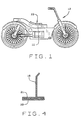
- Fig. 1 shows an elevational view of the composite motorcycle seat cushion 10 of this invention located on the seat I of a conventional "solo" motorcycle 12.
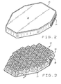
- Fig. 2 shows the motorcycle seat cushion 10 which includes a removable three piece octagonal shaped cover 13 having a reclosable opening 14 at its larger end 15.
- an air cell pad 16 Positioned inside the cover 13 is an air cell pad 16 which includes a base 17, a series of interconnected upstanding air cells 18 and a fill tube assembly 19. This is shown in Fig. 3.
- the cover 13 is similar in construction to the cover shown in Robert H. Graebe Patent No. 5,111,544 which is incorporated herein by reference as fully as if it were set out in its entirety.
- the cellular cushion 16 embodies DRY FLOATATION® technology of ROHO, Inc. and the cells 18 themselves may be of a configuration shown in the air pads described in Graebe Patent Nos. 5,369,828; 4,541,136, etc.
- the inflatable cushion or module 16 is octagonal in shape and, as shown in Fig. 4, comprises a flexible base sheet 20 which has an octagonal shape and a formed flexible top sheet 21 which has the air cells 18 formed therein.
- the two sheets 20, 21 are cemented together at preselected areas to form the module 16.
- the sheets 20, 21 preferably are formed of latex and the top sheet 21 is made by dipping a mandrel into liquid latex.
- a detailed disclosure of a suitable fabrication process and apparatus is disclosed in Graebe Patent No. 4,541,136 incorporated herein by reference as fully as if set out in its entirety.
- the inflatable cellular cushion 16 also may be formed by vacuum or heat forming as set forth in Graebe Patent No. 5,561,875, or by molding in plastic such as polyvinyl chloride (PVC) or polyurethane.
- PVC polyvinyl chloride
- the base 17 is of octagonal shape and comprises a front edge 25 and a longer rear edge 26.
- Side edges 27, 27a are parallel to each other and perpendicular to the front and rear edges 25, 26.
- Connecting the rear edge 26 to the side edges 27, 27a are diverging edges 28, 28a.
- Connecting the side edges 27, 27a to the front edge 25 are converging edges 29, 29a.
- the edges 28, 28a are shorter than the edges 29, 29a.
- the air cells 18 are of pyramidal shape and have a square bottom, rectangular side edges 30, a tapered top formed of four inwardly inclined side walls 31 of substantially trapezoidal shape and a square substantially flat top 32.
- the purpose of the pyramidal shape is to provide a means to collapse the air cell in a controlled manner during the engagement phase by the person sitting on the points formed by the pyramid. The higher the point, the greater the engagement travel which gradually builds up the internal pressure of the cell giving a low force entry zone. This is useful to prevent bottoming out when the cycle is traveling over rough roads and the rider may bounce on the seat at frequent intervals.
- the air cells 18 are spaced from each other by lateral and longitudinal passages and stand independently of each other when erected and filled with air.
- the air cells 18 are configured in lateral rows and includes a rear array "R", a middle array “M” and a front array “F".
- the rear array “R” comprises three rows of cells 18 parallel to the rear edge 26 and spaced along the diverging edges 28, 28a. The rows are of diverging length from four cells 18 adjacent to the rear edge 26 to six cells 18 adjacent to the side edges 27, 27a.
- the middle array “M” comprises three rows of equal length which contain seven cells 18.
- the cell rows in the array "M” are parallel to the front and rear edges 25,26 and perpendicular to the side edges 27,27a.
- the array “M” also is coextensive with the side edges 27, 27a.
- the front array “F” comprises four rows of cells 18 parallel to the front edge 25 and spaced along the converging edges 29, 29a.
- the rows vary in length from six cells 18 adjacent to the side edges 27, 27a to three cells 18 adjacent to the front edge 25.
- the air cells 18 are interconnected pneumatically by a series of air passages in the base 17.
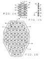
- the air passages include a first peripheral or circumferential series of passages 35 which connect the air cells 18 that are around the periphery of the air cell pad 16 (Figs. 8, 12 and 16), and a second lateral or transverse series of passages 36 which extend from side to side parallel to the front and rear edges 25, 26 and connect the air cells 18 in each row (Figs. 8, 11 and 16).
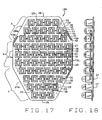
- An alternative construction is to eliminate two or more of the air passages 35 to form separate air chambers each of which would be provided with a fill tube assembly 19 (Figs 17,18).
- a further modification is to provide a manifold type on-off valve arrangement as shown in Graebe Patent Nos. 5,163,196 and 5,502,855.
- the areas of the base 17 between the air cells 18 are cemented together (Fig. 13).
- the end result is that the areas of the bottom sheet 20 that form the bases 37 of the cells 18 tend to bulge outwardly or downwardly (Figs. 9, 10, 13) when air is in the cells 18 and when the cushion is not on a smooth surface.
- Another feature of the air cell pad 16 is the fill tube assembly 19 which is connected to the outside side wall 38 of the outermost air cell 39 in the second row of air cells in the rear array "R".
- An outwardly projecting cylindrical sleeve 40 is molded into the air cell wall 38 and one end of a relatively stiff tubular member 41 is cemented into the sleeve 40.
- the tubular member 41 has an angularly inclined leg portion 42 designed to parallel the base edge 28.
- a fill nozzle 43 Connected to the end of the leg 42 is a fill nozzle 43 having a rotatable on-off valve 44.
- a hold down member 45 forms a loop 46 through which the leg 42 is loosely positioned (Fig. 10).
- the hold down member 45 is fastened to the air pad base 17 by a rivet 47 or other suitable fastener.
- the purpose of the retainer 45 is to position the nozzle 43 so that it is accessible to the user through the cover opening 14.
- the cover 13, as mentioned, contains subject matter in common with Graebe U.S. Patent No. 5,111,544.
- the flexibility of the base 17 allows it to fit over and conform to the often irregular shape of motorcycle seats, autos, truck or boat seats and saddles.
- the cover 13 fits over the seating surface formed by the dome-shaped ends of the cells 18, and also along the sides of the peripheral cells and under the base 17, generally encapsulating the pad 16. Yet, it does not impair the effectiveness of the pad 16, for the ends of the cells 18 are easily displaced toward the base to conform to the shape of the user's buttocks and the base 17 can conform to the shape of the motorcycle seat 11 or other seating surface to which it is applied. Moreover, the cover 13 is easily stripped from the pad 16 to enable the two to be cleaned separately.
- the cover 13 includes a top panel 50, a bottom panel 51 and a side panel 52 which extends between and is joined to the top and bottom panels 50 and 52 along stitch lines 53. Both the top and bottom panels 50 and 51 are octagonal in shape, and that shape matches the shape of the pad base 17.
- the side panel 52 is of a height that generally corresponds to the height of the cells 18 when they are fully extended.
- the stitch lines 53 connecting the lower panel 51 and the upper panel 50 to the side panel 52 extend along the full periphery of the cover and are continuous in the sense that no interruptions exist in the seam that they form.
- the side panel 52 is severed into two sections 54, 55 for a portion of its length around the rear edge 26 and the diverging edges 28, 28a.
- the sections 54, 55 carry a zipper 56 which normally joins them together as one.
- the top panel 50 preferably is formed from a highly elastic and porous fabric, i.e., one that stretches in any direction.
- the elasticity of the top panel 50 enables that panel to conform to the shape of the user's buttocks when the user sits upon the cushion 10.
- the top panel 50 simply follows the contour of the seating surface created by the cells 18 and imposes minimum shear on the user's skin. It detracts little from the capacity of the array of air cells 18 to conform to the shape of the user's buttocks.
- the top panel 50 is porous to vent away moisture. Plastic sheet material for the top panel 50 that has limited elasticity may be used when very good vapor permeability is desired, e.g., when limited cooling is desired.
- the bottom panel 51 is formed from a high friction material, such as the illustrated high friction mesh 60 (Figs. 13 and 14) known as vinyl coated scrim.
- the mesh 60 consists of polyester fibers woven into an open weave and a polyvinyl chloride coating covering the polyester fibers without obliterating the openings of the weave.
- the weave is such that the mesh 60 has relatively thick ribs 61 extending parallel between opposite edges of the panel 50 and thinner connecting segments 62 extending between the ribs 61 and oriented at right angles with respect to the ribs 61, with the spacing between the connecting segments 62 being about the same as the spacing between the ribs 61.
- the coating has a high coefficient of friction against traditional seating and saddle surfaces such as leather, vinyl, wood, metal or fabric, and the friction that develops is particularly effective along the thick ribs 61.
- the coefficient of friction between the coating and such surfaces is substantially greater than the coefficients of friction between the upper and side panels 50 and 52 and such surfaces.
- the mesh 60 is commonly used as an underlayment for throw rugs to prevent them from slipping on traditional flooring materials such as tile, vinyl and hardwood.
- the high friction mesh 60 of the bottom panel 51 prevents the cover, and the cushion over which it fits, from sliding around the motorcycle seat 11. In addition, it admits air to the interior of the cover 13 where the air can circulate through the array of air cells 18. Finally, it permits moisture to drain from the interior of the cover 13, when drain holes 65 are provided in the base 17 of the cushion between the cells 18.
- the bottom panel 51 also may have other mesh patterns and may even be a solid sheet of neoprene rubber or the like which would make the cushion warmer for cold weather use.
- the side panels 52 are formed from a more traditional fabric, i.e., one that has considerable flexibility, yet does not stretch easily. Typical nylon fabric is suited for this purpose.
- Figs 17 and 18 illustrate a modification of the invention in which the air cell pad 16A is divided into compartments "A", "B” and “C".
- the rear array “R” and the middle array “M” and the adjacent row of cells in the front array are all at about the same inflation even though the middle array "M” and the rear array “R” are separated and inflatable through separate nozzles designated by the numerals 43a and 43b.
- the front array “F” also is separated from the other two and is more highly inflated so that the air cells 18 are distended outwardly and upwardly (Fig. 18).
- the fill nozzle 43c is used to fill the cells in the front array "F".
- the raised front cells "F” tend to engage the user if the cycle stops suddenly and to hold and restrain the user from sliding off the seat. This adds to the safety of the cushion 10.
- Other combinations of air cell sections can be used depending on the result desired.
Abstract
Description
- This invention relates to motorcycle seat cushions and more particularly to a free standing pad which can be placed on existing motorcycle seats and which can be removed and carried with the user, but which remain firmly anchored in position on the seat when in use.
- Motorcycles are generally provided with seats for either a single person, called a "solo" seat or a "dual" seat for both the rider and a passenger. When dual seats are provided, the passenger seat is positioned behind the rider's seat and extends over the front portion of the rear fender. When solo seats are employed, the rear fender remains generally uncovered.
- The removable motorcycle seat cushion of this invention can be positioned on either a solo or dual seat cycle.
- Many motorcycle owners use their bikes for long distance travel often over back roads which are not smooth and tend to give the user and/or the passenger a bumping bouncy ride with much vibration. This is known to result in stiffness and soreness in the user, accompanied by lower back pain, hemorrhoidal irritation and extreme fatigue, and gathering of the undergarments ("wedgies"). There are a number of products on the market which strive to obviate these problems. These include covers for seats made of sheepskin sold as MUSTANG WOOLEES; replacement seats with inflatable air chambers sold as MUSTANG AIRLIFT SEAT seats; an inflatable pad known as POCKET P-PAD sold by XZOTIC Cycle Products; gel filled pads such as BUTT BUFFER sold by Warner Associates and SADDLE GEL sold by Travelcade; and spongy foam seats sold as JET STREAM and WIND TUNNEL by Wind-Tech Engineering.
- US-A-5,111,544 describes a cover for a seat cushion having a rectangular base and air cells projecting upwardly from the base to form an array of air cells. The cover comprises a top panel located over the upper ends of the cells and being formed from an elastic fabric, a bottom panel located under the base and covering substantially the entire base, said bottom panel being formed from a high friction material, and a side panel located between and connected to the top and bottom panels at the peripheral margins of the top and bottom panel. The side panel is formed from a flexible fabric, with a portion of the side panel divided into sections which are normally joined, but which may be detached to permit the cover to be removed from or fitted over the cushion.
- In US-A-5,369,828 a seat cushion is described with a flexible modular air cell pad that has a flexible base and a series of upstanding air cells with side walls and a top surface. The air cells have flexible generally vertical side walls sealed to the bottom wall. The air cells are substantially frusto-pyramidal in shape, and have a substantially rectangularly shaped lower section defined by said flexible generally vertical side walls, and a frusto-pyramidal tapered upper section formed from side panels connected to the vertical side walls. The vertical side walls of adjacent cells are separated and spaced apart defining lateral and longitudinal paths and are independently upstanding when inflated. The pneumatically interconnected air cells are formed in lateral transverse rows. Also, a cover comprises a top panel formed from an elastic fabric located over the upper ends of the cells, a bottom panel located under the base and covering substantially the entire base, a side panel located between and connected to the top and bottom panels at the peripheral margins of the top and bottom panel. The side panel is formed from a flexible fabric, with a portion of the side panel being divided into sections which are normally joined, but which may be detached to permit the cover to be removed from or fitted over the pad. The bottom panel is formed from a material with a higher coefficient of friction than top panel or side panel.
- These all differ from the present invention which uses the unique DRY FLOATATION wheelchair cushion and therapeutic mattress technology of Roho, Inc. to provide a cushion which reduces fatigue and related problems in long, often bumpy motorcycle journeys.
- It is a principal object of this invention to provide a new and improved motorcycle seat cushion and, in particular to provide a cushion usable with both solo and dual seat cycles. It is another object to provide a motorcycle seat which, although stable and firmly fixed in use, can be carried intact with the user when leaving the cycle.
- A further object is to provide a motorcycle seat cushion which can be placed on the seats of existing cycles without their modification and which comprises an air cell pad formed with interconnected upstanding flexible air cells and a cover which has a smooth top surface to facilitate user transfer on and off the cushion and a friction generating bottom surface which retains the cushion in a predetermined position on the seat of the motorcycle.
- These and other objects and advantages of the present invention will become more apparent from the detailed description thereof taken with the accompanying drawings.
- In general terms, the invention comprises a motorcycle seat cushion for mounting on the seats of existing motorcycles without special mounting arrangements. The cushion comprises an air pad encased in a cover having a smooth relatively friction-free seating area and a friction generating under surface to fix the cushion on the seat of the motorcycle. The air pad comprises a series of upstanding interconnected air cells to isolate the anatomy of the user from vibration and shock and to provide uniform forces against that portion of the user's anatomy which rests on the cushion.
- In the drawings where like numbers refer to like parts wherever the occur,
- Figure 1 is a side elevational view of a motorcycle with the cushion of this invention placed on the seat thereof;
- Figure 2 is a front, top, right side perspective view of the motorcycle seat of this invention;
- Figure 3 is a front, top, right side perspective view of the air pad component of this invention;
- Figure 4 is a fragmentary sectional view taken along line 4-4 of Figure 3;
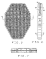
- Figure 5 is a bottom view of the cushion of this invention;
- Figure 6 is a side elevational view;
- Figure 7 is a rear elevational view;
- Figure 8 is a top plan view of the air cell shown in Figure 3;
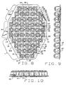
- Figure 9 is a right side elevational view of the air pad of Figure 8;
- Figure 10 is a rear elevational view of the air pad of Figure 8;
- Figure 11 is a vertical sectional view taken along line 11-11 of Figure 5;
- Figure 12 is a vertical sectional view taken along line 12-12 of Figure 8;
- Figure 13 is a vertical sectional view taken along line 13-13 of Figure 8;
- Figure 14 is an enlarged fragmentary plan view of the back wall of the cover of the composite cushion of this invention;
- Figure 15 is a vertical sectional view of a portion of the cover back wall shown in Figure 14;
- Figure 16 is a plan view of the bottom wall of the air pad shown in Figure 3;
- Fig. 17 is a plan view of a modification of the air pad; and
- Fig. 18 is a right side elevational view of the air pad shown in Fig. 17.
-
- As noted, corresponding reference numerals will be used throughout the several figures of the drawings.
- The following detailed description illustrates the invention by way of example and not by way of limitation. This description will clearly enable one skilled in the art to make and use the invention, and describes several embodiments, adaptations, variations, alternatives and uses of the invention, including what we presently believe is the best mode of carrying out the invention.
- Fig. 1 shows an elevational view of the composite
motorcycle seat cushion 10 of this invention located on the seat I of a conventional "solo"motorcycle 12. Fig. 2 shows themotorcycle seat cushion 10 which includes a removable three piece octagonal shapedcover 13 having areclosable opening 14 at itslarger end 15. - Positioned inside the
cover 13 is anair cell pad 16 which includes abase 17, a series of interconnectedupstanding air cells 18 and afill tube assembly 19. This is shown in Fig. 3. - The
cover 13 is similar in construction to the cover shown in Robert H. Graebe Patent No. 5,111,544 which is incorporated herein by reference as fully as if it were set out in its entirety. - The
cellular cushion 16 embodies DRY FLOATATION® technology of ROHO, Inc. and thecells 18 themselves may be of a configuration shown in the air pads described in Graebe Patent Nos. 5,369,828; 4,541,136, etc. The inflatable cushion ormodule 16 is octagonal in shape and, as shown in Fig. 4, comprises aflexible base sheet 20 which has an octagonal shape and a formedflexible top sheet 21 which has theair cells 18 formed therein. The twosheets module 16. Thesheets top sheet 21 is made by dipping a mandrel into liquid latex. A detailed disclosure of a suitable fabrication process and apparatus is disclosed in Graebe Patent No. 4,541,136 incorporated herein by reference as fully as if set out in its entirety. - The inflatable
cellular cushion 16 also may be formed by vacuum or heat forming as set forth in Graebe Patent No. 5,561,875, or by molding in plastic such as polyvinyl chloride (PVC) or polyurethane. - The details of the
air cell pad 16 are shown most clearly in Figs. 3, 8-12 and 16. Thebase 17 is of octagonal shape and comprises afront edge 25 and a longerrear edge 26. Side edges 27, 27a are parallel to each other and perpendicular to the front andrear edges rear edge 26 to the side edges 27, 27a are divergingedges 28, 28a. Connecting the side edges 27, 27a to thefront edge 25 are convergingedges 29, 29a. Theedges 28, 28a are shorter than theedges 29, 29a. - The
air cells 18 are of pyramidal shape and have a square bottom, rectangular side edges 30, a tapered top formed of four inwardlyinclined side walls 31 of substantially trapezoidal shape and a square substantiallyflat top 32. The purpose of the pyramidal shape is to provide a means to collapse the air cell in a controlled manner during the engagement phase by the person sitting on the points formed by the pyramid. The higher the point, the greater the engagement travel which gradually builds up the internal pressure of the cell giving a low force entry zone. This is useful to prevent bottoming out when the cycle is traveling over rough roads and the rider may bounce on the seat at frequent intervals. - The
air cells 18 are spaced from each other by lateral and longitudinal passages and stand independently of each other when erected and filled with air. - The
air cells 18 are configured in lateral rows and includes a rear array "R", a middle array "M" and a front array "F". The rear array "R" comprises three rows ofcells 18 parallel to therear edge 26 and spaced along the diverging edges 28, 28a. The rows are of diverging length from fourcells 18 adjacent to therear edge 26 to sixcells 18 adjacent to the side edges 27, 27a. The middle array "M" comprises three rows of equal length which contain sevencells 18. The cell rows in the array "M" are parallel to the front andrear edges cells 18 parallel to thefront edge 25 and spaced along the convergingedges 29, 29a. The rows vary in length from sixcells 18 adjacent to the side edges 27, 27a to threecells 18 adjacent to thefront edge 25. This configuration allows thecushion 10 to be positioned on a motorcycle seat with the rear array "R" supporting the user's back, coccyx and ischia, and the center and front arrays "M" and "F" supporting the ischia and trochanters of the user. - The
air cells 18 are interconnected pneumatically by a series of air passages in thebase 17. The air passages include a first peripheral or circumferential series ofpassages 35 which connect theair cells 18 that are around the periphery of the air cell pad 16 (Figs. 8, 12 and 16), and a second lateral or transverse series ofpassages 36 which extend from side to side parallel to the front andrear edges air cells 18 in each row (Figs. 8, 11 and 16). Thus all of theair cells 18 are interconnected pneumatically. An alternative construction is to eliminate two or more of theair passages 35 to form separate air chambers each of which would be provided with a fill tube assembly 19 (Figs 17,18). A further modification is to provide a manifold type on-off valve arrangement as shown in Graebe Patent Nos. 5,163,196 and 5,502,855. The areas of the base 17 between theair cells 18 are cemented together (Fig. 13). The end result is that the areas of thebottom sheet 20 that form thebases 37 of thecells 18 tend to bulge outwardly or downwardly (Figs. 9, 10, 13) when air is in thecells 18 and when the cushion is not on a smooth surface. - Another feature of the
air cell pad 16 is thefill tube assembly 19 which is connected to theoutside side wall 38 of theoutermost air cell 39 in the second row of air cells in the rear array "R". An outwardly projectingcylindrical sleeve 40 is molded into theair cell wall 38 and one end of a relatively stifftubular member 41 is cemented into thesleeve 40. Thetubular member 41 has an angularlyinclined leg portion 42 designed to parallel thebase edge 28. Connected to the end of theleg 42 is afill nozzle 43 having a rotatable on-off valve 44. A hold downmember 45 forms aloop 46 through which theleg 42 is loosely positioned (Fig. 10). The hold downmember 45 is fastened to theair pad base 17 by arivet 47 or other suitable fastener. The purpose of theretainer 45 is to position thenozzle 43 so that it is accessible to the user through thecover opening 14. Thecover 13, as mentioned, contains subject matter in common with Graebe U.S. Patent No. 5,111,544. - The flexibility of the
base 17 allows it to fit over and conform to the often irregular shape of motorcycle seats, autos, truck or boat seats and saddles. - The
cover 13 fits over the seating surface formed by the dome-shaped ends of thecells 18, and also along the sides of the peripheral cells and under thebase 17, generally encapsulating thepad 16. Yet, it does not impair the effectiveness of thepad 16, for the ends of thecells 18 are easily displaced toward the base to conform to the shape of the user's buttocks and the base 17 can conform to the shape of themotorcycle seat 11 or other seating surface to which it is applied. Moreover, thecover 13 is easily stripped from thepad 16 to enable the two to be cleaned separately. - The
cover 13 includes atop panel 50, abottom panel 51 and aside panel 52 which extends between and is joined to the top andbottom panels bottom panels pad base 17. Theside panel 52 is of a height that generally corresponds to the height of thecells 18 when they are fully extended. The stitch lines 53 connecting thelower panel 51 and theupper panel 50 to theside panel 52 extend along the full periphery of the cover and are continuous in the sense that no interruptions exist in the seam that they form. Theside panel 52 is severed into twosections rear edge 26 and the diverging edges 28, 28a. Thesections zipper 56 which normally joins them together as one. - The
top panel 50 preferably is formed from a highly elastic and porous fabric, i.e., one that stretches in any direction. The elasticity of thetop panel 50 enables that panel to conform to the shape of the user's buttocks when the user sits upon thecushion 10. Thetop panel 50 simply follows the contour of the seating surface created by thecells 18 and imposes minimum shear on the user's skin. It detracts little from the capacity of the array ofair cells 18 to conform to the shape of the user's buttocks. Thetop panel 50 is porous to vent away moisture. Plastic sheet material for thetop panel 50 that has limited elasticity may be used when very good vapor permeability is desired, e.g., when limited cooling is desired. - The
bottom panel 51, on the other hand, is formed from a high friction material, such as the illustrated high friction mesh 60 (Figs. 13 and 14) known as vinyl coated scrim. Themesh 60 consists of polyester fibers woven into an open weave and a polyvinyl chloride coating covering the polyester fibers without obliterating the openings of the weave. The weave is such that themesh 60 has relativelythick ribs 61 extending parallel between opposite edges of thepanel 50 and thinner connectingsegments 62 extending between theribs 61 and oriented at right angles with respect to theribs 61, with the spacing between the connectingsegments 62 being about the same as the spacing between theribs 61. This forms a pattern of square openings, which are divided bydiagonal segments 63 that extend between the connectingsegments 62, and cross at the centers ofthe square openings. The coating has a high coefficient of friction against traditional seating and saddle surfaces such as leather, vinyl, wood, metal or fabric, and the friction that develops is particularly effective along thethick ribs 61. The coefficient of friction between the coating and such surfaces is substantially greater than the coefficients of friction between the upper andside panels mesh 60 is commonly used as an underlayment for throw rugs to prevent them from slipping on traditional flooring materials such as tile, vinyl and hardwood. It may be obtained from Vantage Industries, Inc., of Atlanta, Ga., or other suitable sources Thehigh friction mesh 60 of thebottom panel 51 prevents the cover, and the cushion over which it fits, from sliding around themotorcycle seat 11. In addition, it admits air to the interior of thecover 13 where the air can circulate through the array ofair cells 18. Finally, it permits moisture to drain from the interior of thecover 13, when drain holes 65 are provided in thebase 17 of the cushion between thecells 18. - The
bottom panel 51 also may have other mesh patterns and may even be a solid sheet of neoprene rubber or the like which would make the cushion warmer for cold weather use. - The
side panels 52 are formed from a more traditional fabric, i.e., one that has considerable flexibility, yet does not stretch easily. Typical nylon fabric is suited for this purpose. - Figs 17 and 18 illustrate a modification of the invention in which the
air cell pad 16A is divided into compartments "A", "B" and "C". In the embodiment shown, the rear array "R" and the middle array "M" and the adjacent row of cells in the front array are all at about the same inflation even though the middle array "M" and the rear array "R" are separated and inflatable through separate nozzles designated by thenumerals 43a and 43b. The front array "F" also is separated from the other two and is more highly inflated so that theair cells 18 are distended outwardly and upwardly (Fig. 18). Thefill nozzle 43c is used to fill the cells in the front array "F". In use, when thecell pad 16A is placed on a motor angle seat, the raised front cells "F" tend to engage the user if the cycle stops suddenly and to hold and restrain the user from sliding off the seat. This adds to the safety of thecushion 10. Other combinations of air cell sections can be used depending on the result desired. - In view of the above, it will be seen that the several objects and advantages of the present invention have been achieved and other advantageous results have been obtained.
- As various changes could be made in the above constructions without departing from the scope of the invention, it is intended that all matter contained in the above description or shown in the accompanying drawings shall be interpreted as illustrative and not in a limiting sense.
Claims (19)
- A motor cycle seat cushion (10) comprising:a) a flexible modular air cell pad (16) having a flexible base (17) and a series of upstanding air cells (18) having side walls (31) and a top surface (32), the air cells (18) having flexible generally vertical side walls (31) sealed to the bottom wall, each of said air cells (18) being substantially fiusto-pyramidal in shape, and having a substantially rectangularly shaped lower section defined by said flexible generally vertical side walls, and a frusto-pyramidal tapered upper section formed from side panels connected to the vertical side walls, the vertical side walls (31) of adjacent cells (18) being separated and spaced apart to define lateral and longitudinal paths and being independently upstanding when inflated, said air cells being formed in lateral transverse rows, some of the rows having a different number of air cells from other of the rows, at least some of the air cells being pneumatically interconnected, and(b) a cover (13) comprising:(1) a top panel (50) located over the upper ends of the cells and being formed from an elastic fabric;(2) a bottom panel (51) located under the base (17) and covering substantially the entire base, said bottom panel being formed from a material with a higher coefficient of friction than top panel (50) or side panel (52); and(3) a side panel (52) located between and connected to the top and bottom panels (50, 51) at the peripheral margins of the top and bottom panel, said side panel being formed from a flexible fabric, a portion of the side panel being divided into sections (54, 55) which are normally joined, but which may be detached to permit the cover (13) to be removed from or fitted over the pad (16).
- The motor cycle seat cushion of claim 1 having an octagonal shape with one end (R) being wider than the other (F).
- The motor cycle seat cushion of claim 1 wherein the air cells (18) have substantially square flexible lower sections and the upper sections have substantially trapezoidal panels with substantially flat top areas.
- The motor cycle seat cushion of claim 1 wherein the cells (18) are all interconnected pneumatically through passages (35, 36) in the flexible base (17).
- The motor cycle seat cushion of claim 4 including air passages (35) in the base (17) connecting the cells around the periphery of the base (17) and lateral air passages (36) connecting the cells in each transverse row.
- The motor cycle seat cushion of claim 1 including at least one air fill assembly (19) connected to the side wall of a peripheral cell.
- The motor cycle seat cushion of claim 6 wherein the air fill assembly (19) includes a fill tube (40, 41) positioned within the periphery (38) of the pad base (17) and parallel to one edge and having an on-off valve (44) on the free end.
- The motor cycle seat cushion of claim 7 wherein the free end (43) of the fill tube is adjacent to the detachable side panel sections (54, 55) to provide the user of the cushion access to the fill tube.
- The motor cycle seat cushion of claim 2 wherein the air cell pad (16) has a rear array ("R"), a middle array ("M"), and a front array ("F") of cells, with the number of cells in the rear array being less than the number of cells in the front array, and there being less cells in the outermost row of cells in the front array than in the outermost row of cells in the rear array.
- The motor cycle seat cushion of claim 1 wherein the cover bottom (51) is a high friction mesh (60).
- The motor cycle seat cushion of claim 10 wherein the high friction mesh (60) is flexible and has parallel ribs (61) with thinner connecting segments (62) extended between the ribs.
- The motor cycle seat cushion of claim 1 wherein the side panel (52) is formed from a highly flexible but substantially non-elastic fabric.
- The motor cycle seat cushion of claim 1 wherein the air cell pad (16) has drain holes (65) in its base (17).
- The motor cycle seat cushion of claim 8 including a tie down (45, 46) positioned around the air fill tube (41) and anchored to the base (17) of the pad to hold the air fill tube and nozzle in a position where it is accessible by the user of the cushion through the side wall panel segments (54, 55).
- The motor cycle seat cushion of claim 11 wherein the bottom panel (51) of the cover (13) is coated with polyvinyl chloride.
- The motor cycle seat cushion of claim 1 wherein the side panel sections (54, 55) of the cover (13) are joined by a zipper arrangement (56).
- The motor cycle seat cushion of claim 1 wherein the flexible base (17) of the air cell pad (16) and the cover (13) allow the cushion to conform to and be retained on irregular seats and saddle surfaces.
- The motor cycle seat cushion of claim 1 wherein the flexible modular air cell pad (16) has a flexible base (17) of irregular shape, and the air cells (18) are divided into arrays ("R", "M", "F") with the cells (18) in each array being pneumatically interconnected, whereby each array can be inflated to a different degree than the other arrays.
- The motor cycle seat cushion of claim 18 wherein the air cell pad base (17) and the cover (13) each have an octagonal shape with one end (R) being wider than the other (F), the smaller end (F) having a separate array ("F") of air cells located toward the front of the surface on which the cushion is located whereby it can have a greater inflation to retard forward movement of the user of the cushion.
Applications Claiming Priority (3)
| Application Number | Priority Date | Filing Date | Title |
|---|---|---|---|
| US77830397A | 1997-01-02 | 1997-01-02 | |
| US778303 | 1997-01-02 | ||
| PCT/US1997/020183 WO1998029010A1 (en) | 1997-01-02 | 1997-11-03 | Motorcycle seat cushion |
Publications (3)
| Publication Number | Publication Date |
|---|---|
| EP0928146A1 EP0928146A1 (en) | 1999-07-14 |
| EP0928146A4 EP0928146A4 (en) | 2000-02-02 |
| EP0928146B1 true EP0928146B1 (en) | 2004-01-07 |
Family
ID=25112894
Family Applications (1)
| Application Number | Title | Priority Date | Filing Date |
|---|---|---|---|
| EP97949367A Expired - Lifetime EP0928146B1 (en) | 1997-01-02 | 1997-11-03 | Motorcycle seat cushion |
Country Status (7)
| Country | Link |
|---|---|
| EP (1) | EP0928146B1 (en) |
| AT (1) | ATE257350T1 (en) |
| AU (1) | AU7887898A (en) |
| CA (1) | CA2257922C (en) |
| DE (1) | DE69727145T2 (en) |
| ES (1) | ES2214643T3 (en) |
| WO (1) | WO1998029010A1 (en) |
Families Citing this family (12)
| Publication number | Priority date | Publication date | Assignee | Title |
|---|---|---|---|---|
| ITVI20030193A1 (en) * | 2003-10-03 | 2005-04-04 | Selle Royal Spa | STRUCTURE OF VISCO-ELASTIC ABSORPTION SUPPORT |
| DE102004006887A1 (en) * | 2004-02-12 | 2005-09-01 | Bayerische Motoren Werke Ag | Motorcycle seat with gas-tight, inflatable elements |
| WO2014105316A1 (en) | 2012-12-27 | 2014-07-03 | High End Seating Solutions | Motorcycle seat and method of making same |
| USD798634S1 (en) | 2016-08-26 | 2017-10-03 | Airhawk International, Llc | Air cushion |
| US10646049B2 (en) | 2017-10-31 | 2020-05-12 | Airhawk International, Llc | Seat cushion |
| USD979263S1 (en) | 2020-10-05 | 2023-02-28 | Airhawk International, Llc | Bicycle seat pan |
| USD979264S1 (en) | 2020-11-30 | 2023-02-28 | Airhawk International, Llc | Air cushion for a bicycle seat |
| USD979266S1 (en) | 2020-12-01 | 2023-02-28 | Airhawk International, Llc | Bicycle seat pan |
| USD979265S1 (en) | 2020-12-01 | 2023-02-28 | Airhawk International, Llc | Air cushion for a bicycle seat |
| EP4294710A1 (en) | 2021-02-16 | 2023-12-27 | Airhawk International, LLC | Bicycle seat assembly with improved comfort and support |
| DE102021103570B3 (en) | 2021-02-16 | 2022-06-23 | Jacques Nordmann | bicycle saddle |
| DE102021118969A1 (en) | 2021-07-22 | 2023-01-26 | Bayerische Motoren Werke Aktiengesellschaft | Seat system for a motorcycle, motorcycle and method for operating a motorcycle |
Family Cites Families (18)
| Publication number | Priority date | Publication date | Assignee | Title |
|---|---|---|---|---|
| GB420292A (en) * | 1933-02-28 | 1934-11-28 | David Moseley & Sons Ltd | Improvements in or relating to pneumatic seats, cushions or the like |
| US2343996A (en) * | 1941-05-16 | 1944-03-14 | Airtress Corp Of America | Pneumatic cushion |
| US2577274A (en) * | 1947-09-25 | 1951-12-04 | Sampson Rubber Products Corp O | Pneumatic cushion |
| US3296635A (en) * | 1964-11-17 | 1967-01-10 | O'hanlan Joseph Treacy | Inflatable seat cushion |
| US3253861A (en) * | 1965-10-20 | 1966-05-31 | Howe Plastics And Chemical Co | Inflatable cushion |
| US3503084A (en) * | 1968-10-18 | 1970-03-31 | Better Sleep Inc | Inflatable cushion |
| US4541136A (en) | 1983-09-01 | 1985-09-17 | Graebe Robert H | Multicell cushion |
| US4698864A (en) * | 1985-11-25 | 1987-10-13 | Graebe Robert H | Cellular cushion |
| US4779924A (en) * | 1987-08-19 | 1988-10-25 | Rudel Myron G | Seat for a motorcycle |
| US4864671A (en) * | 1988-03-28 | 1989-09-12 | Decubitus, Inc. | Controllably inflatable cushion |
| US5052068A (en) * | 1989-11-14 | 1991-10-01 | Graebe Robert H | Contoured seat cushion |
| US5502855A (en) | 1990-11-01 | 1996-04-02 | Graebe; Robert H. | Zoned cellular cushion |
| US5163196A (en) | 1990-11-01 | 1992-11-17 | Roho, Inc. | Zoned cellular cushion with flexible flaps containing inflating manifold |
| US5152023A (en) * | 1990-11-13 | 1992-10-06 | Graebe Robert W | Cellular cushion having sealed cells |
| US5111544A (en) | 1991-07-01 | 1992-05-12 | Graebe Robert H | Cover with elastic top and frictional bottom for a cushion |
| US5561875A (en) | 1992-02-20 | 1996-10-08 | Crown Therapeutics, Inc. | Vacuum/heat formed cushion supported on a fluid permeable manifold |
| ES2137982T3 (en) | 1992-02-20 | 2000-01-01 | Robert H Graebe | MODULAR CUSHION STRUCTURE WITH A FOAM BASE. |
| US5634685A (en) * | 1995-03-20 | 1997-06-03 | Herring; Charles | Inflatable/deflatable motorcycle seat cushion |
-
1997
- 1997-11-03 WO PCT/US1997/020183 patent/WO1998029010A1/en active IP Right Grant
- 1997-11-03 AT AT97949367T patent/ATE257350T1/en not_active IP Right Cessation
- 1997-11-03 ES ES97949367T patent/ES2214643T3/en not_active Expired - Lifetime
- 1997-11-03 DE DE69727145T patent/DE69727145T2/en not_active Expired - Lifetime
- 1997-11-03 AU AU78878/98A patent/AU7887898A/en not_active Abandoned
- 1997-11-03 CA CA002257922A patent/CA2257922C/en not_active Expired - Fee Related
- 1997-11-03 EP EP97949367A patent/EP0928146B1/en not_active Expired - Lifetime
Also Published As
| Publication number | Publication date |
|---|---|
| ES2214643T3 (en) | 2004-09-16 |
| CA2257922A1 (en) | 1998-07-09 |
| ATE257350T1 (en) | 2004-01-15 |
| CA2257922C (en) | 2004-05-25 |
| EP0928146A1 (en) | 1999-07-14 |
| WO1998029010A1 (en) | 1998-07-09 |
| DE69727145D1 (en) | 2004-02-12 |
| AU7887898A (en) | 1998-07-31 |
| EP0928146A4 (en) | 2000-02-02 |
| DE69727145T2 (en) | 2004-11-25 |
Similar Documents
| Publication | Publication Date | Title |
|---|---|---|
| EP0928146B1 (en) | Motorcycle seat cushion | |
| US5419612A (en) | Inflatable seat assembly | |
| US6223673B1 (en) | Floatable recreational park | |
| US5318348A (en) | Cushioned sling chair | |
| US6223678B1 (en) | Inflatable kayak | |
| US5634685A (en) | Inflatable/deflatable motorcycle seat cushion | |
| US4862536A (en) | Back support device | |
| US6623080B2 (en) | Cellular cushion vehicle seat system | |
| US5524961A (en) | Pneumatic bicycle saddle | |
| US20050121953A1 (en) | Motorcycle seat | |
| US5356198A (en) | Bicycle and exerciser seat | |
| US6334227B1 (en) | Seat | |
| TW201418092A (en) | Ventilated saddle for bicycles, motorcycles and/or other pedal driven machines | |
| US6039396A (en) | Bicycle seat and seat cover | |
| US6532613B2 (en) | Three dimensional star shaped pliable chair | |
| US5392477A (en) | Sleeping bag with inflatable wedge portion | |
| GB973731A (en) | Improvements in or relating to seats,chairs,chairbacks and the like | |
| US2558389A (en) | Bicycle seat | |
| US5333930A (en) | Surface for a seat of a cycle | |
| US20020069464A1 (en) | Saddle seat supplement and pad | |
| WO1994008839A1 (en) | A seat cover | |
| EP0706933B1 (en) | Motorcycle seat | |
| WO2012177271A1 (en) | Inflatable device | |
| US2672923A (en) | Vehicle seat | |
| JPH0433193Y2 (en) |
Legal Events
| Date | Code | Title | Description |
|---|---|---|---|
| PUAI | Public reference made under article 153(3) epc to a published international application that has entered the european phase |
Free format text: ORIGINAL CODE: 0009012 |
|
| 17P | Request for examination filed |
Effective date: 19981221 |
|
| AK | Designated contracting states |
Kind code of ref document: A1 Designated state(s): AT BE CH DE DK ES FI FR GB GR IE IT LI LU MC NL PT SE |
|
| A4 | Supplementary search report drawn up and despatched |
Effective date: 19991221 |
|
| AK | Designated contracting states |
Kind code of ref document: A4 Designated state(s): AT BE CH DE DK ES FI FR GB GR IE IT LI LU MC NL PT SE |
|
| 17Q | First examination report despatched |
Effective date: 20020318 |
|
| GRAH | Despatch of communication of intention to grant a patent |
Free format text: ORIGINAL CODE: EPIDOS IGRA |
|
| GRAS | Grant fee paid |
Free format text: ORIGINAL CODE: EPIDOSNIGR3 |
|
| GRAA | (expected) grant |
Free format text: ORIGINAL CODE: 0009210 |
|
| AK | Designated contracting states |
Kind code of ref document: B1 Designated state(s): AT BE CH DE DK ES FI FR GB GR IE IT LI LU MC NL PT SE |
|
| PG25 | Lapsed in a contracting state [announced via postgrant information from national office to epo] |
Ref country code: NL Free format text: LAPSE BECAUSE OF FAILURE TO SUBMIT A TRANSLATION OF THE DESCRIPTION OR TO PAY THE FEE WITHIN THE PRESCRIBED TIME-LIMIT Effective date: 20040107 Ref country code: LI Free format text: LAPSE BECAUSE OF FAILURE TO SUBMIT A TRANSLATION OF THE DESCRIPTION OR TO PAY THE FEE WITHIN THE PRESCRIBED TIME-LIMIT Effective date: 20040107 Ref country code: IT Free format text: LAPSE BECAUSE OF FAILURE TO SUBMIT A TRANSLATION OF THE DESCRIPTION OR TO PAY THE FEE WITHIN THE PRE;WARNING: LAPSES OF ITALIAN PATENTS WITH EFFECTIVE DATE BEFORE 2007 MAY HAVE OCCURRED AT ANY TIME BEFORE 2007. THE CORRECT EFFECTIVE DATE MAY BE DIFFERENT FROM THE ONE RECORDED.SCRIBED TIME-LIMIT Effective date: 20040107 Ref country code: FI Free format text: LAPSE BECAUSE OF FAILURE TO SUBMIT A TRANSLATION OF THE DESCRIPTION OR TO PAY THE FEE WITHIN THE PRESCRIBED TIME-LIMIT Effective date: 20040107 Ref country code: CH Free format text: LAPSE BECAUSE OF FAILURE TO SUBMIT A TRANSLATION OF THE DESCRIPTION OR TO PAY THE FEE WITHIN THE PRESCRIBED TIME-LIMIT Effective date: 20040107 Ref country code: BE Free format text: LAPSE BECAUSE OF FAILURE TO SUBMIT A TRANSLATION OF THE DESCRIPTION OR TO PAY THE FEE WITHIN THE PRESCRIBED TIME-LIMIT Effective date: 20040107 Ref country code: AT Free format text: LAPSE BECAUSE OF FAILURE TO SUBMIT A TRANSLATION OF THE DESCRIPTION OR TO PAY THE FEE WITHIN THE PRESCRIBED TIME-LIMIT Effective date: 20040107 |
|
| REG | Reference to a national code |
Ref country code: GB Ref legal event code: FG4D |
|
| REG | Reference to a national code |
Ref country code: CH Ref legal event code: EP |
|
| REG | Reference to a national code |
Ref country code: IE Ref legal event code: FG4D |
|
| REF | Corresponds to: |
Ref document number: 69727145 Country of ref document: DE Date of ref document: 20040212 Kind code of ref document: P |
|
| PG25 | Lapsed in a contracting state [announced via postgrant information from national office to epo] |
Ref country code: SE Free format text: LAPSE BECAUSE OF FAILURE TO SUBMIT A TRANSLATION OF THE DESCRIPTION OR TO PAY THE FEE WITHIN THE PRESCRIBED TIME-LIMIT Effective date: 20040407 Ref country code: GR Free format text: LAPSE BECAUSE OF FAILURE TO SUBMIT A TRANSLATION OF THE DESCRIPTION OR TO PAY THE FEE WITHIN THE PRESCRIBED TIME-LIMIT Effective date: 20040407 Ref country code: DK Free format text: LAPSE BECAUSE OF FAILURE TO SUBMIT A TRANSLATION OF THE DESCRIPTION OR TO PAY THE FEE WITHIN THE PRESCRIBED TIME-LIMIT Effective date: 20040407 |
|
| NLV1 | Nl: lapsed or annulled due to failure to fulfill the requirements of art. 29p and 29m of the patents act | ||
| REG | Reference to a national code |
Ref country code: CH Ref legal event code: PL |
|
| REG | Reference to a national code |
Ref country code: ES Ref legal event code: FG2A Ref document number: 2214643 Country of ref document: ES Kind code of ref document: T3 |
|
| PG25 | Lapsed in a contracting state [announced via postgrant information from national office to epo] |
Ref country code: LU Free format text: LAPSE BECAUSE OF NON-PAYMENT OF DUE FEES Effective date: 20041103 Ref country code: IE Free format text: LAPSE BECAUSE OF NON-PAYMENT OF DUE FEES Effective date: 20041103 |
|
| ET | Fr: translation filed | ||
| PLBE | No opposition filed within time limit |
Free format text: ORIGINAL CODE: 0009261 |
|
| STAA | Information on the status of an ep patent application or granted ep patent |
Free format text: STATUS: NO OPPOSITION FILED WITHIN TIME LIMIT |
|
| PG25 | Lapsed in a contracting state [announced via postgrant information from national office to epo] |
Ref country code: MC Free format text: LAPSE BECAUSE OF NON-PAYMENT OF DUE FEES Effective date: 20041130 |
|
| 26N | No opposition filed |
Effective date: 20041008 |
|
| REG | Reference to a national code |
Ref country code: IE Ref legal event code: MM4A |
|
| PG25 | Lapsed in a contracting state [announced via postgrant information from national office to epo] |
Ref country code: PT Free format text: LAPSE BECAUSE OF NON-PAYMENT OF DUE FEES Effective date: 20040607 |
|
| PGFP | Annual fee paid to national office [announced via postgrant information from national office to epo] |
Ref country code: DE Payment date: 20101126 Year of fee payment: 14 |
|
| PGFP | Annual fee paid to national office [announced via postgrant information from national office to epo] |
Ref country code: GB Payment date: 20101124 Year of fee payment: 14 |
|
| PGFP | Annual fee paid to national office [announced via postgrant information from national office to epo] |
Ref country code: FR Payment date: 20111128 Year of fee payment: 15 Ref country code: ES Payment date: 20111124 Year of fee payment: 15 |
|
| GBPC | Gb: european patent ceased through non-payment of renewal fee |
Effective date: 20121103 |
|
| REG | Reference to a national code |
Ref country code: FR Ref legal event code: ST Effective date: 20130731 |
|
| REG | Reference to a national code |
Ref country code: DE Ref legal event code: R119 Ref document number: 69727145 Country of ref document: DE Effective date: 20130601 |
|
| PG25 | Lapsed in a contracting state [announced via postgrant information from national office to epo] |
Ref country code: DE Free format text: LAPSE BECAUSE OF NON-PAYMENT OF DUE FEES Effective date: 20130601 |
|
| PG25 | Lapsed in a contracting state [announced via postgrant information from national office to epo] |
Ref country code: FR Free format text: LAPSE BECAUSE OF NON-PAYMENT OF DUE FEES Effective date: 20121130 Ref country code: GB Free format text: LAPSE BECAUSE OF NON-PAYMENT OF DUE FEES Effective date: 20121103 |
|
| REG | Reference to a national code |
Ref country code: ES Ref legal event code: FD2A Effective date: 20140305 |
|
| PG25 | Lapsed in a contracting state [announced via postgrant information from national office to epo] |
Ref country code: ES Free format text: LAPSE BECAUSE OF NON-PAYMENT OF DUE FEES Effective date: 20121104 |