EP0928106A2 - Data recording/reproducing apparatus and data recording/reproducing method - Google Patents
Data recording/reproducing apparatus and data recording/reproducing method Download PDFInfo
- Publication number
- EP0928106A2 EP0928106A2 EP99106070A EP99106070A EP0928106A2 EP 0928106 A2 EP0928106 A2 EP 0928106A2 EP 99106070 A EP99106070 A EP 99106070A EP 99106070 A EP99106070 A EP 99106070A EP 0928106 A2 EP0928106 A2 EP 0928106A2
- Authority
- EP
- European Patent Office
- Prior art keywords
- data
- tracks
- track
- search
- reproduction
- Prior art date
- Legal status (The legal status is an assumption and is not a legal conclusion. Google has not performed a legal analysis and makes no representation as to the accuracy of the status listed.)
- Withdrawn
Links
Images


Classifications
-
- H—ELECTRICITY
- H04—ELECTRIC COMMUNICATION TECHNIQUE
- H04N—PICTORIAL COMMUNICATION, e.g. TELEVISION
- H04N5/00—Details of television systems
- H04N5/76—Television signal recording
- H04N5/78—Television signal recording using magnetic recording
- H04N5/782—Television signal recording using magnetic recording on tape
- H04N5/7824—Television signal recording using magnetic recording on tape with rotating magnetic heads
- H04N5/7826—Television signal recording using magnetic recording on tape with rotating magnetic heads involving helical scanning of the magnetic tape
-
- H—ELECTRICITY
- H04—ELECTRIC COMMUNICATION TECHNIQUE
- H04N—PICTORIAL COMMUNICATION, e.g. TELEVISION
- H04N5/00—Details of television systems
- H04N5/76—Television signal recording
- H04N5/78—Television signal recording using magnetic recording
- H04N5/782—Television signal recording using magnetic recording on tape
- H04N5/783—Adaptations for reproducing at a rate different from the recording rate
-
- H—ELECTRICITY
- H04—ELECTRIC COMMUNICATION TECHNIQUE
- H04N—PICTORIAL COMMUNICATION, e.g. TELEVISION
- H04N5/00—Details of television systems
- H04N5/76—Television signal recording
- H04N5/91—Television signal processing therefor
- H04N5/92—Transformation of the television signal for recording, e.g. modulation, frequency changing; Inverse transformation for playback
- H04N5/926—Transformation of the television signal for recording, e.g. modulation, frequency changing; Inverse transformation for playback by pulse code modulation
- H04N5/9261—Transformation of the television signal for recording, e.g. modulation, frequency changing; Inverse transformation for playback by pulse code modulation involving data reduction
-
- H—ELECTRICITY
- H04—ELECTRIC COMMUNICATION TECHNIQUE
- H04N—PICTORIAL COMMUNICATION, e.g. TELEVISION
- H04N5/00—Details of television systems
- H04N5/76—Television signal recording
- H04N5/78—Television signal recording using magnetic recording
- H04N5/782—Television signal recording using magnetic recording on tape
- H04N5/7824—Television signal recording using magnetic recording on tape with rotating magnetic heads
- H04N5/7826—Television signal recording using magnetic recording on tape with rotating magnetic heads involving helical scanning of the magnetic tape
- H04N5/78263—Television signal recording using magnetic recording on tape with rotating magnetic heads involving helical scanning of the magnetic tape for recording on tracks inclined relative to the direction of movement of the tape
- H04N5/78266—Television signal recording using magnetic recording on tape with rotating magnetic heads involving helical scanning of the magnetic tape for recording on tracks inclined relative to the direction of movement of the tape using more than one track for the recording of one television field or frame, i.e. segmented recording
-
- H—ELECTRICITY
- H04—ELECTRIC COMMUNICATION TECHNIQUE
- H04N—PICTORIAL COMMUNICATION, e.g. TELEVISION
- H04N5/00—Details of television systems
- H04N5/76—Television signal recording
- H04N5/91—Television signal processing therefor
- H04N5/92—Transformation of the television signal for recording, e.g. modulation, frequency changing; Inverse transformation for playback
- H04N5/9201—Transformation of the television signal for recording, e.g. modulation, frequency changing; Inverse transformation for playback involving the multiplexing of an additional signal and the video signal
- H04N5/9205—Transformation of the television signal for recording, e.g. modulation, frequency changing; Inverse transformation for playback involving the multiplexing of an additional signal and the video signal the additional signal being at least another television signal
Definitions
- the present invention relates to an apparatus and a method for recording/reproducing a digital signal such as a digitized video signal, and in particular to a helical scan type digital VCR capable of reproducing recorded data at a reproduction speed different from the normal reproduction speed and a recording/reproducing method using the VCR.
- a conventional technique for reproducing data at a variable-speed by using a digital VCR is disclosed, for example, in Japanese Laid-Open Patent Publication No. 2-94071.
- a video signal is recorded on tracks provided on a magnetic tape by using a magnetic head.
- the track on the magnetic tape has sub-code areas located along the paths of scanning by the magnetic head during a variable-speed reproduction, and still frame data extracted from the video signal is distributively recorded in the sub-code areas over a plurality of tracks.
- the still frame data is obtained by reproducing the data recorded in the sub-code area, thereby displaying a picture.
- tracks to be scanned are selected, and the phase of the magnetic tape and the magnetic head is controlled by using a capstan motor.
- variable reproduction speed allowing still frame data to be stably obtained is limited to one kind of speed.
- limitation to only one kind of variable reproduction speed for VCRs has been inefficient, and the demand for VCRs having a plurality of variable reproduction speeds has been increased.
- the present invention thus concerns a data recording/reproducing apparatus records data in a plurality of tracks located on a tape like recording medium and reproduces recorded data from the tracks, wherein the apparatus generates a plurality of blocks by vertically dividing a picture, generates search data for variable-speed reproduction corresponding to data for each block, and sequentially places the search data in a predetermined region of each track, in the order from a top block of the picture along a direction of tape travel.
- a data recording/reproducing apparatus records data in a plurality of tracks located on a tape like recording medium and reproduces recorded data from the tracks, wherein the apparatus generates a plurality of blocks by horizontally dividing a picture, generates search data for variable-speed reproduction corresponding to data for each block, and sequentially places the search data in a predetermined region of each track, in the order from the left outermost block of the picture along a direction of tape travel.
- a data recording/reproducing method records data in a plurality of tracks located on a tape like recording medium and reproduces recorded data from the tracks, the method including the steps of generating a plurality of blocks by vertically dividing a picture, generating search data for variable-speed reproduction corresponding to data for each block, and sequentially placing the search data in a predetermined region of each track, in the order from a top block of the picture along a direction of tape travel.
- a data recording/reproducing method records data in a plurality of tracks located on a tape like recording medium and reproduces recorded data from the tracks, the method including the steps of generating a plurality of blocks by horizontally dividing a picture, generating search data for variable-speed reproduction corresponding to data for each block, and sequentially placing the search data in a predetermined region of each track, in the order from the left outermost block of the picture along a direction of tape travel.
- the invention described herein makes possible the advantages of providing data reproducing method and apparatus capable of: (1) displaying a reproduced picture of high quality in variable-speed reproduction without phase-control by a capstan motor, by reproducing data recorded in a search data region; (2) displaying a reproduced picture of high quality at a plurality of variable reproduction speeds in a wide range, by using a different cycle of update of the picture in accordance with each variable reproduction speed; and (3) smoothly shifting between normal-speed reproduction and the variable-speed reproduction in an arbitrary position of a recording medium, decreasing the amount of excessive scanning during the search in the variable-speed reproduction.
- a data reproducing apparatus 30 of Example 1 of the present invention will be described with reference to the accompanying drawings.
- Figure 1 shows a block diagram for a data recording/reproducing apparatus 30 .
- the data recording/reproducing apparatus 30 includes a normal reproduction encoder 1 , a searching encoder 2 , a formatter 3 , an error correction encoder 4 , a modulator 5 , a magnetic head 6 , a demodulator 8 , an error correction demodulator 9 , a deformatter 10 , a normal reproduction decoder 11 , a searching decoder 12 , a switch 13 , a pinch roller 21 and a capstan motor 22 .
- a video signal input to the data recording/reproducing apparatus 30 is recorded onto a magnetic tape 7 via the magnetic head 6 .
- the data recorded on the magnetic tape 7 is reproduced via the magnetic head 6 .
- the magnetic head 6 includes, for example, two heads 6a and 6b provided on a cylinder 20 .
- the heads 6a and 6b have azimuth angles R and L , respectively, which are different from each other.
- the magnetic head 6 of Example 1 is composed of two heads, an additional head may be further provided on the magnetic head 6 .
- a combination head (see Figure 3C ) composed of two closely spaced heads is preferably used.
- the data recording/reproducing apparatus 30 has a normal reproduction mode for reproducing data at a normal speed and a search mode for reproducing data at one or more variable (high) reproduction speeds.
- the input signal When the input signal is recorded, the magnetic tape 7 is driven by the capstan motor 22 and the pinch roller 21 , so that it travels at a normal play speed.
- the input signal may include a video signal, a speech signal and the like.
- the input signal In a case where the input signal is an analog signal, it is A/D converted into a digital signal.
- the input signal is a digital video signal, and that image data is recorded onto the magnetic tape 7 .
- the data to be recorded onto the magnetic tape is not limited to image data.
- An input digital video signal is fed to the normal reproduction encoder 1 and the searching encoder 2 .
- the normal reproduction encoder 1 compresses the image data if necessary, and outputs the data to the formatter 3 as normal reproduction data.
- the searching encoder 2 generates search data from the received digital video signal, and outputs it to the formatter 3 .
- the search data is, for example, data generated by more highly compressing the image data than the normal reproduction encoder 1 which allows it to reproduce a picture from a smaller amount of data.
- the searching encoder 2 may output the input digital video signal to serve as search data according to the format.
- the normal reproduction encoder 1 may generate encoded data by using intra-frame and interframe compressing of the image data, and the searching encoder 2 may generate encoded data only by using intra-frame compressing of the image data.
- the formatter 3 provides, for each track, a normal data region to be used for a normal-speed reproduction and a search data region to be used for variable-speed reproduction. Normal reproduction data fed from the normal reproduction encoder 1 is allocated to the normal data region. Search data fed from the searching encoder 2 is allocated to the search data region. In this way, a track set composed of (2N + 1) tracks having one identical search data recorded by the head 6a and a track set composed of (2N + 1) tracks having another identical search data recorded by the head 6b are formed.
- image data of one frame may be recorded after being divided into M portions.
- Example 1 a case where the dividing number M is two, and one frame is divided into upper and lower halves will be described.
- the searching encoder 2 extracts image data T representing image of one frame at a time t and splits it into upper and lower halves. Then, the upper half of the image data T is compressed and encoded to generate data Ta , which is output for the track recorded by the head 6a . Likewise, the searching encoder 2 compresses and encodes the lower half of the image data T to generate data Tb , which is output for the track recorded by the head 6b .
- the searching encoder 2 outputs the data Ta to the head 6a while the head 6a is recording a track set (i.e., (2N + 1) tracks).
- the searching encoder 2 outputs the data Tb to the head 6b while the head 6b is recording the corresponding track set (i.e., (2N + 1) tracks).
- the searching encoder 2 extracts image data (T + 1) of the following one frame at a time t from the input video signal. In a manner similar to the above-mentioned one, the upper half of the image data (T + 1) is compressed and encoded to generate data (T + 1)a , which is output for the track recorded by the head 6a . Likewise, the searching encoder 2 compresses and encodes a lower half of the image data (T + 1) to generate data (T + 1)b , which is output for the track recorded by the head 6b . The searching encoder 2 outputs the data (T + 1)a to the head 6a while the head 6a is recording the following track set. The searching encoder 2 outputs the data (T + 1)b to the head 6b while the head 6b records the following track set.
- the amount of data included in the upper half of the picture is not required to be the same as that of the lower half. Moreover, the amount of data included in the upper (lower) half of one picture is not required to be the same as that of another picture. Namely, the length of a search data region along the track can be arbitrarily selected in accordance with the amount of data, for each track set.
- the formatter 3 has a memory capable of storing image data for at least one track and arranges the normal reproduction data and the search data by the sync block composed of a plurality of data so that the normal reproduction data and the search data are recorded at predetermined positions within the track, respectively. Moreover, the formatter 3 adds an identification flag indicating whether it is the normal reproduction data or the search data to the arranged data on the track in memory. Then, starting from the leading edge of the tracks, the resultant data is sequentially output to the error correction encoder 4 .
- the length of the sync block for storing the search data is not necessarily equal to that for storing the normal reproduction data.
- the error correction encoder 4 receives data output from the formatter 3 and adds an error correction code for each sync block as one unit and another error correction code for a plurality of sync blocks as one unit.
- the modulator 5 receives an output from the error correction encoder 4 , adds synchronization information and ID information thereto, modulates and outputs it to the magnetic head 6 .
- the modulated signal is recorded on the magnetic tape 7 by the magnetic head 6 .
- (2N + 1) 7 tracks having the same azimuth angle and recorded by one of the heads 6a and 6b form one track set.
- each of search data regions recording identical search data is located by the formatter 3 at the same position in each track, and is recorded at the same position in the corresponding track on the magnetic tape 7 .
- the search data regions of the tracks included in one track set are located parallel to the direction of tape travel, thereby forming one search data zone.
- the search data zone can be located so as not overlap with the audio signal region.
- Figure 2 shows a pattern of tracks recorded on the magnetic tape 7 in accordance with a format arranged by the formatter 3 .
- the formatter 3 provides one search data region for each track.
- the left outermost track shown in Figure 2 has a search data region 200 located between normal data regions 100 and 300 .
- Normal data regions 100 through 129 and 300 through 329 of successively located tracks form a normal data zone along the direction of tape travel.
- search data regions 200 through 229 form a search data zone along the direction of tape travel.
- image data of one frame is recorded by using ten tracks. That is, image data T of one frame at a time t is recorded on normal data regions 100 through 109 and 300 through 309 . Next, image data (T + 1) of one frame at a time (t + 1) is recorded on normal data regions 110 through 119 and 310 through 319 .
- data Ta obtained by highly compressing the upper half of the image data T of one frame at a time t is recorded in a search data region 200 .
- data Tb obtained by highly compressing the lower half of the image data T of one frame at a time t is recorded in a search data region 201 .
- the data Ta is placed on every other track to be recorded in search data regions 200 , 202 ... 212 .
- the data Tb is placed on every other track to be recorded in search data regions 201 , 203 ... 213 .
- data (T + 1)a obtained by highly compressing the upper half of the image data (T + 1) of one frame at a time (t + 1) is recorded in a search data region 214
- data (T + 1)b obtained by highly compressing the lower half of the image data (T + 1) of one frame at a time (t + 1) is recorded in a search data region 215 .
- the data (T + 1)a is placed on every other track to be recorded in search data regions 214 , 216 ... 228
- the data (T + 1)b is placed on every other track to be recorded in search data regions 215 , 217 ... 229 .
- the magnetic tape 7 is driven at a predetermined speed by the capstan motor 22 and the pinch roller 21 . In the variable-speed reproduction, the magnetic tape 7 travels at a speed (N + 0.5) times the normal speed.
- the data recorded on the magnetic tape 7 is reproduced by the magnetic head 6 .
- the demodulator 8 demodulates reproduced data, removes synchronization information and decodes ID information.
- the resultant data is output to the error correction decoder 9 , which performs error correction for the received data in units of one sync block and in units of a plurality of sync blocks.
- the resultant data is output to the deformatter 10 .
- the deformatter 10 divides the data into normal reproduction data and search data.
- a part of the ID information of the sync block may be used in the error correction decoder 9 .
- the normal reproduction data is decoded by the normal reproduction decoder 11
- the search data is decoded by the searching decoder 12 .
- the switch 13 selects an output from the normal reproduction decoder 11 in the normal reproduction and an output from the searching decoder 12 in the variable-speed reproduction and outputs this as a video signal.
- the magnetic head 6 is a combination head as shown in Figure 3C composed of two heads 6a (azimuth angle R) and 6b (azimuth angle L) mounted on the cylinder 20 which are closely spaced to each other will be described.
- a distance (stagger) between the heads 6a and 6b is taken into consideration.
- a gap length (head width Tw) of the magnetic head 6 is equal to a track pitch Tp.
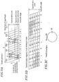
- Figure 3A is a schematic view showing the pattern of tracks formed by the combination head.
- Figure 3B is an enlarged view showing the search data region shown in Figure 3A .
- paths 500 and 502 show the scanning of the head 6a in the reproduction at a speed 3.5 times the normal play speed
- paths 501 and 503 show the scanning of the head 6b in the reproduction at a speed 3.5 times the normal play speed.
- the data recorded on a target track can be effectively reproduced if each of the heads recovers the track with the width of more than a half of the track width (track pitch).
- the data recorded in shadowed portions of the tracks shown in Figures 3A and 3B is effectively reproduced by the scanning performed by each head.
- all the tracks of an R azimuth angle hereinafter, referred to as "R-tracks" have identical search data.
- the head 6a can reproduce necessary data from the search data regions of any two R-tracks on which the head 6a has scanned.
- L-tracks since all the tracks of an L azimuth angle (hereinafter, referred to as "L-tracks”) have identical search data, without phase control of the capstan motor 22 , the head 6b can reproduce necessary data from the search data regions of any two L-tracks on which the head 6b has scanned.
- L-tracks L azimuth angle
- the data Ta obtained by compressing the upper half of the image data T at a time t is recorded on each R-track, being divided into a plurality of data groups.
- the data Ta is divided into, for example, five data groups ( A1, A2, A3, A4 and A5 ) so that each data group is recorded onto a sync block as search data.
- the data Tb obtained by compressing the lower half of the image data T at a time t is divided into five data groups ( B1, B2, B3, B4 and B5 ) so as to be recorded on the search data region of the L-track.
- the head 6a scans along a path 500 , data groups A1, A2 and A3 are reproduced from one R-track. Then, by the next scanning (a path 502 ) performed by the head 6a , data groups A4 and A5 are reproduced from another R-track. Accordingly, by complementarily performing two scannings, the head 6a can effectively reproduce all the data recorded in the search data region having the same azimuth angle as that of the head 6a .
- the head 6b (azimuth angle L) scans along a path 501 owing to a stagger.
- the head 6b reproduces data groups B1 and B2 from one L-track by the scanning of the path 501 , and reproduces data groups B3 , B4 and B5 from another L-track by the next scanning (a path 503 ).
- the operation of the head 6b is similar to that of the head 6a .
- all the effective data recorded in the search data region of the tracks having the same azimuth angle as can be complementarily reproduced by performing two scannings of each of the heads 6a and 6b . This reproduction is possible irrespective of whether there is a stagger or not, and without the phase control of the capstan motor 22 .
- FIG. 4A is a schematic diagram showing the pattern of tracks formed by the magnetic head 6 to which the heads 6a and 6b are mounted with an angular distance of 180° therebetween.
- Figure 4B is an enlarged view showing the search data regions shown in Figure 4A .
- paths 504 and 506 show the scanning of the head 6a in the reproduction at a speed 3.5 times the normal reproduction speed
- the paths 505 and 507 show the scanning of the head 6b in the reproduction at a speed 3.5 times the normal reproduction speed.
- the search data zone within the cycle S all the search data regions of R-tracks have identical search data, while all the search data regions of L-tracks have identical search data.
- the head 6a can reproduce necessary data from the search data regions of two R-tracks by performing two complementary scannings.
- the head 6b cannot effectively reproduce data from the L-track from only the first scanning (path 505 ), the head 6b scans the entire search data region of one L-track by the second scanning (path 507 ). At this time, as shown in detail in Figure 4B , it is possible to reproduce all the data groups ( B1, B2, B3, B4 and B5 ) of the search data region of the L-track.
- the scanning order of the heads 6a and 6b may be reversed.
- the search data region of each track is located at the same corresponding position on the track. Since the R-tracks and L-tracks are alternately located, the search data regions for one picture form a search data zone along the direction of tape travel. This allows reliable reproduction of the search data, without being significantly affected by the curves of the tracks.
- Figure 5B is an enlarged view of the search data regions in the track pattern shown in Figure 5A .
- Figure 5C schematically shows the track pattern in a case where the head width is larger than the track pitch (Tw > Tp).
- Figure 5D is an enlarged view of the search data regions in the track pattern shown in Figure 5C .
- the head 6a reproduces the region of the track with a width more than a half of the track pitch, the data recorded on the magnetic tape 7 (i.e., with an adequate signal to noise ratio) can be reproduced at an error rate lower than a critical one.
- the head width Tw is equal to the track pitch Tp, as shown in Figures 5A and 5B , the head 6a reproduces data groups A1, A2 and A3 by the first scanning (path 500 ) and data groups A4 and A5 by the next scanning (path 502 ).
- the head 6a reproduces data groups A1, A2, A3 and A4 by the first scanning (the path 500 ) and data groups A3, A4 and A5 by the next scanning (the path 502 ).
- the data groups A3 and A4 are reproduced twice.
- the areas recovered by the head 6a are relatively small.
- the reproduction output from the head 6a is of a lower level.
- the reliability of data can be improved by increasing the redundancy of the data reproduced from such a search data region with an S/N ratio which is not so high.
- the speed control of the capstan motor 22 can be performed with a wider range of permissible variations.
- Example 1 the normal data region for use in the normal reproduction and the search data region for use in the variable-speed reproduction are provided within one track, and a standard speed of variable-speed reproduction is set at a speed (N + 0.5) times the normal reproduction speed.
- the same data is recorded in each of the search data regions of the track set of (2N + 1) tracks.
- each of the heads 6a and 6b scans within the track set twice.
- the head width of the magnetic head 6 (heads 6a and 6b ) larger than the track pitch, the error rate in the reproduced data can be reduced.
- speed control of the magnetic tape 7 can have a wider permission range of variations.
- the search data region of each track is located at the same position on the respective track, and thereby the search data zone is formed along the direction of tape travel.
- the search data is unlikely to be affected by the warping of tracks.
- the search data can be reliably reproduced.
- the complete search data recorded in the search data region can be reproduced at the variable-speed reproduction at a speed (N x + 0.5) (N x : a natural number) times the normal reproduction speed in the range from (-N - 0.5) times to (N + 0.5) times. Also in the reproduction at a variable reproduction speed other than the above-mentioned one and in a transfer state from one reproduction speed to another, a part of the search data can be reproduced, whereby an image can be displayed.
- Example 1 one track set is made of (2N + 1) tracks having the same azimuth angle. However, the same effects can also be obtained when one track set includes more than (2N + 1) tracks, though the redundancy increases.
- the search data region of each track is located at the same position on the respective track.
- the search data region may be differently located with respect to one track set from another in units of the track set of (2N + 1) tracks having the same azimuth angle, as far as each of the search data regions of all the tracks in one track set is located at one specific position on the respective track. For example, it may be located so as not to overlap with the specific regions such as an audio data region determined in accordance with standards.
- Example 1 the case of the magnetic head 6 having two adjacent heads in combination and a case where the magnetic head 6 has two heads spaced with an angular interval of 180° have been described. However, the same effects may be obtained by using a magnetic head having other configurations.
- the data recorded in the R-track and that recorded in the L-track are updated at the same time every S tracks.
- the update position of the data can be arbitrarily determined in each of the search data regions.
- the update position of the data in the search data region of the R-track may be different from that of the L-track.
- Example 1 the same standard variable reproduction speed is set for the search data region of the R-track and for that of the L-track.
- the standard variable reproduction speed may be different from one search data region to another, whereby the range of the variable reproduction speed can be widened.
- Example 1 the data placed in the search data region of one track set is different from the data placed in the search data region of another track set, each track set being composed of (2N + 1) tracks and having a different azimuth angle.
- the same data may be recorded in the search data region of the track having a different azimuth angle. And in this case, the redundancy of the data increases, which may decrease the error ratio.
- Example 1 the data to be recorded in the search data regions of the R and L azimuth angles are divided into five data groups. However, the dividing number may be arbitrarily determined. Thus, the number of data groups in the search data region of the R azimuth angle may be different from that of the L azimuth angle.
- Example 1 the normal reproduction encoder 1 and the searching encoder 2 are separately provided. However, they may be implemented by one device serving both as the normal reproduction encoder 1 and the searching encoder 2 .
- Example 1 the normal reproduction data corresponding to a picture of one frame is recorded in ten tracks.
- the number of tracks can be arbitrarily determined and may be different for each frame.
- the input signal is a digital video signal obtained by A/D converting an analog video signal.
- the input signal may be data resulting from a digital video signal subject to intra-frame and inter-frame compressions. In this case, it is unnecessary for the normal reproduction encoder 1 to perform the data compressions.
- the searching encoder 2 may extract intra-frame-compressed data from the input data, so as to generate search data from the extracted data.
- the dividing number and the manner of dividing the picture may be arbitrarily selected.
- the dividing number M may be determined so that the picture is divided into three or more parts.
- the picture may be divided into a left half and a right half, or into blocks of arbitrary sizes and arbitrary shapes.
- Example 1 only the speed control of the capstan motor 22 is used in the variable-speed reproduction. Additional phase control of the capstan motor 22 may be used so as to improve the variable reproduction speed.
- the position or the like of the search data region is defined by formats and the like, there is no need to use the identification flag indicating that which includes the search data.
- Example 3 a data recording/reproducing apparatus of Example 3 of the present invention will be described with reference to accompanying drawings.
- the overall configuration of the data recording/reproducing apparatus of Example 3 is similar to that of the data recording/reproducing apparatus 30 (see Figure 1 ), and the operations thereof are the same as those described in Example 1. The detailed description thereof will be omitted in Example 3.
- the data placement in the normal data zone is the same as that of Example 1, and the detailed descriptions thereof will be omitted.
- Figure 7 shows a track pattern formed on the magnetic tape 7 in Example 3.
- the formatter 3 locates the normal data and the search data regions in each track.
- the search data regions for recording the same search data are placed at the same corresponding position in each track and recorded at the same position in the corresponding track of the magnetic tape 7 . Accordingly, the search data regions included in one track set are located along the direction of tape travel of the magnetic tape 7 , thus forming a search data zone.
- the formatter 3 places normal reproduction data into normal data regions 100 through 120 and 300 through 329 , and places search data into search data regions 200 through 229 .
- the data Ta generated from the upper half of the image data T at a time t is recorded in search data regions 200 through 207 of successive eight tracks. Then, the data Tb generated from the lower half of the image data T at a time t is recorded in the search data regions of 208 through 215 of successive eight tracks. This recording process is sequentially repeated.
- the magnetic head 6 has two heads 6a and 6b which are mounted on the cylinder 20 with an angular distance of 180° therebetween.
- the gap length (head width Tw ) of the magnetic head 6 is equal to the track pitch Tp .
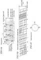
- Figure 8A is a schematic view showing the track pattern formed by the magnetic head 6 having heads 6a and 6b mounted with an angular distance of 180° therebetween.
- Figure 8B is an enlarged view of the search data regions shown in Figure 8A .
- paths 508 and 510 show the scanning of the head 6a in the variable-speed reproduction at a speed four times the normal reproduction speed
- paths 509 and 511 show the scanning of the head 6b in the variable-speed reproduction at a speed four times the normal reproduction speed.
- the data recorded on a target track can be effectively reproduced when each of the heads recovers the region with a width more than a half of the track width.
- the data recorded in shadowed portions of the tracks shown in Figures 8A and 8B is effectively reproduced by the scanning performed by each head.
- all the search data regions of all tracks have identical data. Consequently, by two complementary scanning performed by the heads 6a and 6b , or by one scanning performed by the head 6a or 6b , necessary data can be effectively reproduced. By repeating such scannings one after another, all the data recorded in the search data regions can be effectively reproduced by the heads 6a and 6b , without the phase control of the capstan motor 22 .
- the reliability of data can be improved by increasing the redundancy of the data reproduced from the search data region where an area recovered by each head is relatively small and of which reproduction output from the head is of a low level. Moreover, a permissible range of variation in the speed control of the capstan motor 22 can be widened.
- N' an even number
- the same data is recorded in each of the search data regions of the track set of successive 2N' tracks, thereby forming a search data zone.
- N' an even number
- each of the heads 6a and 6b having different azimuth angles scans once the search data zone within the track set.
- the search data region of each track is located at the position corresponding to the same position on the track for all the tracks.
- the search data region may be arbitrarily located, as far as each of the search data regions of all the 2N' tracks in one track set are located at one specific position in the respective track. For example, it may be located so as not to overlap with the specific regions such as an audio data region determined in accordance with standards.
- Example 3 one track set includes successive 2N' tracks. However, the same effects can also be obtained when one track set includes more than 2N' tracks, though it results in an increase of the redundancy.
- Example 3 only the speed control of the capstan motor 22 is used for the variable-speed reproduction. Additional phase control of the capstan motor 22 may be used so as to improve the variable reproduction speed.
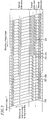
- FIG 23 schematically shows the track pattern formed by the data recording/reproducing apparatus of Example 11.
- the configuration of the data recording/reproducing apparatus is the same as that described in Example 1.
- one-frame image data is recorded in four tracks as normal reproduction data A .
- the normal reproduction data A is generated, for example, by intra-frame compressing one-frame image data T at a time t by the normal reproduction encoder 1 .
- each of the search data A1, A2, A3 and A4 is repeatedly recorded in a track set of (2N + 1) tracks selected by every other track. More specifically, as shown in Figure 23 , the search data A1 and A2 are recorded in the successive 2 ⁇ (2N + 1) tracks, followed by the search data A3 and A4 recorded in the successive 2 ⁇ (2N + 1) tracks. Accordingly, in the search data zone, the search data corresponding to the image data T at a time t are recorded by using 4 ⁇ (2N + 1) tracks in total.
- the normal reproduction data A is placed in the normal data regions 901 located in the substantial center of the 4 ⁇ (2N + 1) tracks in which the search data is recorded.
- the placement of normal reproduction data A in the shifted position is realized by delaying the recording time using a memory.
- variable-speed reproduction similar to Example 1, all the data recorded in the search data regions can be effectively reproduced by two complementary scannings of the heads 6a and 6b or by either one of the two scannings.
- search data is reproduced in the order of A1, A2 , ...
- a display picture is updated when all the data ( A1, A2, A3 and A4 ) necessary for forming one picture (i.e., one frame) are obtained.
- the same operation can be applied to a case where variable-speed reproduction is performed in the opposite direction.
- the position at which a reproduced picture is updated and replaced with the picture corresponding to the search data of the normal reproduction data A (the image data T at a time t), (i.e., the position at which all of A1, A2, A3 and A4 are reproduced) is shifted by 2 ⁇ (2N + 1) tracks from the starting point of the normal data region 901 in which the normal reproduction data A is recorded.
- the head has to return by 2 ⁇ (2N + 1) tracks in order to start the normal reproduction from the corresponding normal picture data ( A ).
- the head has to return by 2 ⁇ (2N + 1) tracks in order to start the normal reproduction from the picture obtained by the search.
- the excess track amount of searching in the normal direction is 4 ⁇ (2N + 1) tracks.
- the amount of excessive search in the normal direction can be reduced to half.
- the search data of the one-frame image data for normal reproduction is placed in the search data region in a plurality of track sets including the tracks and the preceding and succeeding tracks, whereby the amount of excessive search can be reduced.
- Example 11 the track from which recording of the image data A for normal reproduction is started is located at the center of 4 ⁇ (2N + 1) tracks.
- four tracks for recording the image data A for normal reproduction may be located at the center portion of 4 ⁇ (2N + 1) tracks.
- the image data A for normal reproduction can be placed in the tracks following the tracks in which the search data A1, A2, A3 and A4 are recorded. In such a case, the amount of excessive search can be further reduced.
- the normal data regions are located at the approximate center tracks of the track set forming the search data region for the normal data region.
- the same effects can be obtained by locating the normal data region at the approximate center tracks of these plurality of tracks.
- FIG. 24A through 24D show the track pattern formed by the data recording/reproducing apparatus of Example 12 and updating of a picture.
- one-frame image data is divided into six horizontal strips, which are referred to as C1, C2, C3, C4, C5 and C6 blocks in the order from the top portion to the bottom portion of the picture.
- the search data is sequentially recorded in the search data regions along the direction of tape travel from image data C1 at the top portion of the picture.
- the data C1 is initially recorded in the search data region of one track (e.g., R-track).
- the data C2 is recorded in the search region of its adjacent track (e.g., L-track).
- Each of the data C1 and C2 is recorded in the (2N + 1) tracks having the same azimuth angle.
- the data C3 and C4 are alternately recorded by using the next 2 ⁇ (2N + 1) tracks.
- the data C5 and C6 are alternately recorded in the next 2 ⁇ (2N + 1) tracks.
- the image data of each frame is recorded one after another.
- the cycle of update of a reproduced picture becomes 84/300 second.
- the data C1 and C2 , the data C3 and C4 , the data C5 and C6 and the following data can be obtained by two blocks from each of 42 tracks every 28/30 second.
- the reproduced picture is partially updated by two blocks.
- the reproduced picture is sequentially updated from each two blocks of horizontally divided blocks from the top to the bottom of the picture.
- the reproduced picture is updated from each two blocks of horizontally divided blocks from the bottom to the top of the picture.
- the picture to be displayed is updated per picture in the high speed reproduction, while the picture to be displayed is sequentially updated per block in the order of from the top or bottom portion of the picture in the low speed reproduction.
- a picture easy to see is reproduced, and the search can be performed with a reduced amount of excessive search.
- FIG. 25A through 25D show the track pattern formed by the data recording/reproducing apparatus of Example 13 and the state of update of a picture.
- one-frame image data is divided into six longitudinal strips D1, D2, D3, D4, D5 and D6 blocks from the left portion to the right portion of the picture.
- the search data are sequentially recorded in the search data regions along the direction of tape travel in the order from image data D1 at the left outermost portion of the picture.
- a reproduced picture is updated per two blocks as shown in Figure 25D .
- the reproduced picture is partially updated by each two blocks of vertically divided blocks from the left to the right of the picture.
- search in the opposite direction the reproduced picture is partially updated from each two blocks of vertically divided blocks from the right to the left of the picture.
- the cycle of update of the reproduced picture is shortened, and a reproduced picture easy to see is obtained in the variable-speed reproduction.
- the amount of excessive search can be reduced.
- the direction of tape travel can be easily grasped.
- the picture to be displayed is updated per picture in the high speed reproduction, while the picture to be displayed is updated per block in the order of from the left or right of the picture in the low speed reproduction.
- a picture easy to see is reproduced, and the search can be performed with a reduced amount of excessive search.
- the direction of the search can be easily judged.
- the picture is divided in the horizontal or vertical direction.
- the picture can be divided into arbitrary blocks on the picture.
- the reproduced image is updated per picture in the high speed reproduction, while the reproduced picture is updated per block in the low speed reproduction. In this way, the amount of excessive search can be alleviated.
- one search data region is provided in each track.
- a plurality of search data regions may be provided in each track.
- the image data is updated for each of horizontally or vertically divided blocks of the reproduced picture. Accordingly, the reproduced picture gradually changes from the top to bottom portion or from the left to right portion. Thus, a reproduced picture easy to see is obtained.
- the image data is updated for each of horizontally or vertically divided blocks of the reproduced picture. Accordingly, the reproduced picture gradually changes from the bottom to top portion or from the right to left portion. Thus, a reproduced picture easy to see is obtained.
- the normal data and the search data are described in units of frames. However, if they are processed in units of fields, the same effects can be obtained.
Abstract
Description
- The present invention relates to an apparatus and a method for recording/reproducing a digital signal such as a digitized video signal, and in particular to a helical scan type digital VCR capable of reproducing recorded data at a reproduction speed different from the normal reproduction speed and a recording/reproducing method using the VCR.
- A conventional technique for reproducing data at a variable-speed by using a digital VCR is disclosed, for example, in Japanese Laid-Open Patent Publication No. 2-94071.
- According to this conventional technique, a video signal is recorded on tracks provided on a magnetic tape by using a magnetic head. The track on the magnetic tape has sub-code areas located along the paths of scanning by the magnetic head during a variable-speed reproduction, and still frame data extracted from the video signal is distributively recorded in the sub-code areas over a plurality of tracks. In variable-speed reproduction, the still frame data is obtained by reproducing the data recorded in the sub-code area, thereby displaying a picture. In order to prevent the magnetic head from scanning off the paths on the distributively located sub-code areas, tracks to be scanned are selected, and the phase of the magnetic tape and the magnetic head is controlled by using a capstan motor.
- However, in such a conventional variable-speed reproduction apparatus using sub-code areas, the variable reproduction speed allowing still frame data to be stably obtained is limited to one kind of speed. Recently, limitation to only one kind of variable reproduction speed for VCRs has been inefficient, and the demand for VCRs having a plurality of variable reproduction speeds has been increased. In order to reproduce data at a plurality of variable reproduction speeds by using the conventional technique, it is required to locate the data on each path scanned by the head at different variable reproduction speeds. This makes the data format on the magnetic tape complicated, as well as decreasing the efficiency in using a recording medium because of recording waste data.
- Since a picture reproduced at a variable-speed is displayed as a series of intermittent still pictures, in order to update the displayed picture, all the data for one still frame have to be reproduced from a plurality of sub-code areas. Because the sub-code areas being distributively located over a plurality of tracks, when all the data for one still frame have been reproduced from the sub-code area for a variable-speed reproduction, data for normal-speed reproduction corresponding to the still frame data exists at a position far away from the track in which this sub-code area is recorded. Accordingly, there is a problem of an increasing amount of excessive scanning in variable-speed reproduction.
- The present invention thus concerns a data recording/reproducing apparatus records data in a plurality of tracks located on a tape like recording medium and reproduces recorded data from the tracks, wherein the apparatus generates a plurality of blocks by vertically dividing a picture, generates search data for variable-speed reproduction corresponding to data for each block, and sequentially places the search data in a predetermined region of each track, in the order from a top block of the picture along a direction of tape travel.
- According to another aspect of the invention, a data recording/reproducing apparatus records data in a plurality of tracks located on a tape like recording medium and reproduces recorded data from the tracks, wherein the apparatus generates a plurality of blocks by horizontally dividing a picture, generates search data for variable-speed reproduction corresponding to data for each block, and sequentially places the search data in a predetermined region of each track, in the order from the left outermost block of the picture along a direction of tape travel.
- According to another aspect of the invention, a data recording/reproducing method records data in a plurality of tracks located on a tape like recording medium and reproduces recorded data from the tracks, the method including the steps of generating a plurality of blocks by vertically dividing a picture, generating search data for variable-speed reproduction corresponding to data for each block, and sequentially placing the search data in a predetermined region of each track, in the order from a top block of the picture along a direction of tape travel.
- According to another aspect of the invention, a data recording/reproducing method records data in a plurality of tracks located on a tape like recording medium and reproduces recorded data from the tracks, the method including the steps of generating a plurality of blocks by horizontally dividing a picture, generating search data for variable-speed reproduction corresponding to data for each block, and sequentially placing the search data in a predetermined region of each track, in the order from the left outermost block of the picture along a direction of tape travel.
- Thus, the invention described herein makes possible the advantages of providing data reproducing method and apparatus capable of: (1) displaying a reproduced picture of high quality in variable-speed reproduction without phase-control by a capstan motor, by reproducing data recorded in a search data region; (2) displaying a reproduced picture of high quality at a plurality of variable reproduction speeds in a wide range, by using a different cycle of update of the picture in accordance with each variable reproduction speed; and (3) smoothly shifting between normal-speed reproduction and the variable-speed reproduction in an arbitrary position of a recording medium, decreasing the amount of excessive scanning during the search in the variable-speed reproduction.
- These and other advantages of the present invention will become apparent to those skilled in the art upon reading and understanding the following detailed description with reference to the accompanying drawings.
-
- Figure 1 is a block diagram showing a data recording/reproducing apparatus of the present invention in Example 1.
- Figure 2 is a diagram showing the track pattern of the present invention in Example 1.
- Figure 3A is a schematic diagram showing the track pattern when using a combination head of the present invention in Example 1.
- Figure 3B is an enlarged view showing the search data regions when using a combination head in Example 1.
- Figure 3C is a diagram showing the arrangement of the heads in the combination head.
- Figure 4A is a schematic diagram showing the track pattern of the present invention when using a head having two heads set apart from each other by an angular distance of 180° in Example 1.
- Figure 4B is an enlarged view showing the search data regions when using a head having two heads set apart from each other by an angular distance of 180° in Example 1.
- Figure 4C is a diagram showing the arrangement of heads set apart from each other by an angular distance of 180°.
- Figure 5A is a schematic diagram showing the track pattern in the case where the head width is equal to the track pitch.
- Figure 5B is an enlarged view showing the search, data regions in the case where the head width is equal to the track pitch.
- Figure 5C is a schematic diagram showing the track pattern in the case where the head width is larger than the track pitch.
- Figure 5D is an enlarged view showing the search data regions in the case where the head width is larger than the track pitch.
- Figure 7 is a diagram showing the track pattern in Example 3 of the present invention.
- Figure 8A is a schematic diagram showing the track pattern in Example 3 of the present invention.
- Figure 8B is an enlarged view showing the search data regions in Example 3 of the present invention.
- Figure 8C is a diagram showing the arrangement of heads in Example 3.
- Figure 23 is a schematic diagram showing the track pattern in Example 11 of the present invention.
- Figure 24A is a diagram for explaining the division of a picture in Example 12.
- Figure 24B is a schematic diagram showing the track pattern in Example 12 of the present invention.
- Figure 24C is a diagram for explaining an update of a picture in high speed reproduction in Example 12.
- Figure 24D is a diagram for explaining an update of a picture in low speed reproduction in Example 12.
- Figure 25A is a diagram for explaining the division of a picture in Example 13.
- Figure 25B is a schematic diagram showing the track pattern in Example 13 of the present invention.
- Figure 25C is a diagram for explaining an update of a picture in high speed reproduction in Example 13.
- Figure 25D is a diagram for explaining an update of a picture in low speed reproduction in Example 13.
-
- A data reproducing apparatus 30 of Example 1 of the present invention will be described with reference to the accompanying drawings.
- Figure 1 shows a block diagram for a data recording/reproducing apparatus 30. As shown in Figure 1, the data recording/reproducing apparatus 30 includes a normal reproduction encoder 1, a searching encoder 2, a formatter 3, an error correction encoder 4, a modulator 5, a magnetic head 6, a demodulator 8, an error correction demodulator 9, a deformatter 10, a normal reproduction decoder 11, a searching decoder 12, a switch 13, a pinch roller 21 and a capstan motor 22. A video signal input to the data recording/reproducing apparatus 30 is recorded onto a magnetic tape 7 via the magnetic head 6. The data recorded on the magnetic tape 7 is reproduced via the magnetic head 6.
- As shown in Figure 3C or 4C, the magnetic head 6 includes, for example, two heads 6a and 6b provided on a cylinder 20. The heads 6a and 6b have azimuth angles R and L, respectively, which are different from each other. Though the magnetic head 6 of Example 1 is composed of two heads, an additional head may be further provided on the magnetic head 6. In the case of performing a recording operation, a combination head (see Figure 3C) composed of two closely spaced heads is preferably used.
- The data recording/reproducing apparatus 30 has a normal reproduction mode for reproducing data at a normal speed and a search mode for reproducing data at one or more variable (high) reproduction speeds. Hereinafter, operations of the data recording/reproducing apparatus 30 will be described with respect to the case where a standard variable reproduction speed
- When the input signal is recorded, the magnetic tape 7 is driven by the capstan motor 22 and the pinch roller 21, so that it travels at a normal play speed. The input signal may include a video signal, a speech signal and the like. In a case where the input signal is an analog signal, it is A/D converted into a digital signal. Hereinafter, it is assumed that the input signal is a digital video signal, and that image data is recorded onto the magnetic tape 7. However, the data to be recorded onto the magnetic tape is not limited to image data.
- An input digital video signal is fed to the normal reproduction encoder 1 and the searching encoder 2. The normal reproduction encoder 1 compresses the image data if necessary, and outputs the data to the formatter 3 as normal reproduction data. The searching encoder 2 generates search data from the received digital video signal, and outputs it to the formatter 3. The search data is, for example, data generated by more highly compressing the image data than the normal reproduction encoder 1 which allows it to reproduce a picture from a smaller amount of data. Alternatively, the searching encoder 2 may output the input digital video signal to serve as search data according to the format. For example, the normal reproduction encoder 1 may generate encoded data by using intra-frame and interframe compressing of the image data, and the searching encoder 2 may generate encoded data only by using intra-frame compressing of the image data.
- With respect to the standard variable reproduction speed of v = 3.5 (times the normal reproduction speed) (N = 3), while each of the heads 6a and 6b records
- Herein, in order to reduce the number of search data regions, image data of one frame may be recorded after being divided into M portions. In Example 1, a case where the dividing number M is two, and one frame is divided into upper and lower halves will be described.
- The searching encoder 2 extracts image data T representing image of one frame at a time t and splits it into upper and lower halves. Then, the upper half of the image data T is compressed and encoded to generate data Ta, which is output for the track recorded by the head 6a. Likewise, the searching encoder 2 compresses and encodes the lower half of the image data T to generate data Tb, which is output for the track recorded by the head 6b. The searching encoder 2 outputs the data Ta to the head 6a while the head 6a is recording a track set (i.e., (2N + 1) tracks). The searching encoder 2 outputs the data Tb to the head 6b while the head 6b is recording the corresponding track set (i.e., (2N + 1) tracks).
- After the magnetic heads 6a and 6b each records one track set, the searching encoder 2 extracts image data (T + 1) of the following one frame at a time t from the input video signal. In a manner similar to the above-mentioned one, the upper half of the image data (T + 1) is compressed and encoded to generate data (T + 1)a, which is output for the track recorded by the head 6a. Likewise, the searching encoder 2 compresses and encodes a lower half of the image data (T + 1) to generate data (T + 1)b, which is output for the track recorded by the head 6b. The searching encoder 2 outputs the data (T + 1)a to the head 6a while the head 6a is recording the following track set. The searching encoder 2 outputs the data (T + 1)b to the head 6b while the head 6b records the following track set.
- Herein, the amount of data included in the upper half of the picture is not required to be the same as that of the lower half. Moreover, the amount of data included in the upper (lower) half of one picture is not required to be the same as that of another picture. Namely, the length of a search data region along the track can be arbitrarily selected in accordance with the amount of data, for each track set.
- The formatter 3 has a memory capable of storing image data for at least one track and arranges the normal reproduction data and the search data by the sync block composed of a plurality of data so that the normal reproduction data and the search data are recorded at predetermined positions within the track, respectively. Moreover, the formatter 3 adds an identification flag indicating whether it is the normal reproduction data or the search data to the arranged data on the track in memory. Then, starting from the leading edge of the tracks, the resultant data is sequentially output to the error correction encoder 4. The length of the sync block for storing the search data is not necessarily equal to that for storing the normal reproduction data.
- The error correction encoder 4 receives data output from the formatter 3 and adds an error correction code for each sync block as one unit and another error correction code for a plurality of sync blocks as one unit. The modulator 5 receives an output from the error correction encoder 4, adds synchronization information and ID information thereto, modulates and outputs it to the magnetic head 6. The modulated signal is recorded on the magnetic tape 7 by the magnetic head 6.
- Herein,
- Figure 2 shows a pattern of tracks recorded on the magnetic tape 7 in accordance with a format arranged by the formatter 3. In Example 1, the formatter 3 provides one search data region for each track. For example, the left outermost track shown in Figure 2 has a search data region 200 located between normal data regions 100 and 300. Normal data regions 100 through 129 and 300 through 329 of successively located tracks form a normal data zone along the direction of tape travel. Likewise, search data regions 200 through 229 form a search data zone along the direction of tape travel. By using the formatter 3, normal reproduction data into the normal data regions 100 through 129 and 300 through 329, and search data are recorded into the search data regions 200 through 229.
- In the normal data zone, image data of one frame is recorded by using ten tracks. That is, image data T of one frame at a time t is recorded on normal data regions 100 through 109 and 300 through 309. Next, image data (T + 1) of one frame at a time (t + 1) is recorded on normal data regions 110 through 119 and 310 through 319.
- On the other hand, in the search data zone, search data obtained by highly compressing the image data of one frame is recorded by using
- As described hereinbefore, where M = 2 (M = the dividing number by which one picture is divided), in the search data region, data corresponding to a picture of one frame is recorded by using
- Next, with reference to Figure 1 again, the operation of the data recording/reproducing apparatus 30 in reproducing data will be described. The magnetic tape 7 is driven at a predetermined speed by the capstan motor 22 and the pinch roller 21. In the variable-speed reproduction, the magnetic tape 7 travels at a speed (N + 0.5) times the normal speed. The data recorded on the magnetic tape 7 is reproduced by the magnetic head 6. The demodulator 8 demodulates reproduced data, removes synchronization information and decodes ID information. The resultant data is output to the error correction decoder 9, which performs error correction for the received data in units of one sync block and in units of a plurality of sync blocks. The resultant data is output to the deformatter 10. Based on the identification flag, the deformatter 10 divides the data into normal reproduction data and search data. A part of the ID information of the sync block may be used in the error correction decoder 9. The normal reproduction data is decoded by the normal reproduction decoder 11, while the search data is decoded by the searching decoder 12. The switch 13 selects an output from the normal reproduction decoder 11 in the normal reproduction and an output from the searching decoder 12 in the variable-speed reproduction and outputs this as a video signal.
- With reference to Figures 3A through 3C, a method for reproducing image data from the search data region will be described.
- First, the case where the magnetic head 6 is a combination head as shown in Figure 3C composed of two heads 6a (azimuth angle R) and 6b (azimuth angle L) mounted on the cylinder 20 which are closely spaced to each other will be described. In the following description, a distance (stagger) between the heads 6a and 6b is taken into consideration. Furthermore, it is assumed that a gap length (head width Tw) of the magnetic head 6 is equal to a track pitch Tp. Figure 3A is a schematic view showing the pattern of tracks formed by the combination head. Figure 3B is an enlarged view showing the search data region shown in Figure 3A.
- In Figure 3A, paths 500 and 502 show the scanning of the head 6a in the reproduction at a speed 3.5 times the normal play speed, while paths 501 and 503 show the scanning of the head 6b in the reproduction at a speed 3.5 times the normal play speed. Herein, it is assumed that the data recorded on a target track can be effectively reproduced if each of the heads recovers the track with the width of more than a half of the track width (track pitch). In this case, the data recorded in shadowed portions of the tracks shown in Figures 3A and 3B is effectively reproduced by the scanning performed by each head.
- As can be seen from Figure 3A, in the reproduction at a speed 3.5 times the normal speed, each of the heads 6a (azimuth angle R) and 6b (azimuth angle L) certainly scans twice the search data zone within an update cycle
- In the search data region, the data Ta obtained by compressing the upper half of the image data T at a time t is recorded on each R-track, being divided into a plurality of data groups. In Example 1, the data Ta is divided into, for example, five data groups (A1, A2, A3, A4 and A5) so that each data group is recorded onto a sync block as search data. Likewise, the data Tb obtained by compressing the lower half of the image data T at a time t is divided into five data groups (B1, B2, B3, B4 and B5) so as to be recorded on the search data region of the L-track.
- Herein, in a case where the head 6a scans along a path 500, data groups A1, A2 and A3 are reproduced from one R-track. Then, by the next scanning (a path 502) performed by the head 6a, data groups A4 and A5 are reproduced from another R-track. Accordingly, by complementarily performing two scannings, the head 6a can effectively reproduce all the data recorded in the search data region having the same azimuth angle as that of the head 6a. On the other hand, the head 6b (azimuth angle L) scans along a path 501 owing to a stagger. The head 6b reproduces data groups B1 and B2 from one L-track by the scanning of the path 501, and reproduces data groups B3, B4 and B5 from another L-track by the next scanning (a path 503). In a case where there is no distance (stagger) between the heads 6a and 6b, the operation of the head 6b is similar to that of the head 6a. Thus, by sequentially repeating the scanning, all the effective data recorded in the search data region of the tracks having the same azimuth angle as can be complementarily reproduced by performing two scannings of each of the heads 6a and 6b. This reproduction is possible irrespective of whether there is a stagger or not, and without the phase control of the capstan motor 22.
- Next, a case where the magnetic head 6 has heads 6a and 6b which are mounted on the cylinder 20 apart from each other by an angular distance of 180° as shown in Figure 4C will be described. Herein, it is assumed that the gap length (head width Tw) of the magnetic head 6 is equal to the track pitch Tp. Figure 4A is a schematic diagram showing the pattern of tracks formed by the magnetic head 6 to which the heads 6a and 6b are mounted with an angular distance of 180° therebetween. Figure 4B is an enlarged view showing the search data regions shown in Figure 4A.
- In Figure 4A, paths 504 and 506 show the scanning of the head 6a in the reproduction at a speed 3.5 times the normal reproduction speed, while the paths 505 and 507 show the scanning of the head 6b in the reproduction at a speed 3.5 times the normal reproduction speed. Herein, it is assumed that when each of the head recovers the region of the track with a width more than a half of the track width, the data recorded in the track can be effectively reproduced. Then, the data recorded in the shadowed portions of the tracks in Figures 4A and 4C can be effectively reproduced by the scanning of each head.
- As can be seen from Figures 4A and 4B, in the reproduction at a speed 3.5 times the normal reproduction speed, each of the head 6a (azimuth angle R) and the head 6b (azimuth angle L) certainly scans twice the search data zone within an update cycle
- By sequentially repeating the scanning as described above, all the effective data recorded in the search data region can be reliably reproduced by two complementary scannings, or by either one of two scannings.
- As described above, in one track set composed of (2N + 1) tracks having the same azimuth angle, the search data region of each track is located at the same corresponding position on the track. Since the R-tracks and L-tracks are alternately located, the search data regions for one picture form a search data zone along the direction of tape travel. This allows reliable reproduction of the search data, without being significantly affected by the curves of the tracks.
- Next, a case where the gap length (head width Tw) of the magnetic head 6 is larger than the track pitch Tp will be described with reference to Figures 5A through 5D. Though the operation of the head 6a will be described as an example, the same operation can be applied to the head 6b. Furthermore, the description herein does not depend on the location or the number of heads.
- Figure 5A schematically shows the track pattern in a case where the head width is equal to the track pitch (Tw = Tp). Figure 5B is an enlarged view of the search data regions in the track pattern shown in Figure 5A. Figure 5C schematically shows the track pattern in a case where the head width is larger than the track pitch (Tw > Tp). Figure 5D is an enlarged view of the search data regions in the track pattern shown in Figure 5C.
- Now, it is assumed that when the head 6a reproduces the region of the track with a width more than a half of the track pitch, the data recorded on the magnetic tape 7 (i.e., with an adequate signal to noise ratio) can be reproduced at an error rate lower than a critical one. In a case where the head width Tw is equal to the track pitch Tp, as shown in Figures 5A and 5B, the head 6a reproduces data groups A1, A2 and A3 by the first scanning (path 500) and data groups A4 and A5 by the next scanning (path 502).
- In a case where the head width Tw is larger than the track pitch Tp, as shown in Figures 5C and 5D, the head 6a reproduces data groups A1, A2, A3 and A4 by the first scanning (the path 500) and data groups A3, A4 and A5 by the next scanning (the path 502). Thus, the data groups A3 and A4 are reproduced twice. In the data groups A3 and A4, the areas recovered by the head 6a are relatively small. As a result, the reproduction output from the head 6a is of a lower level. The reliability of data can be improved by increasing the redundancy of the data reproduced from such a search data region with an S/N ratio which is not so high. Furthermore, the speed control of the capstan motor 22 can be performed with a wider range of permissible variations.
- As described hereinbefore, in Example 1, the normal data region for use in the normal reproduction and the search data region for use in the variable-speed reproduction are provided within one track, and a standard speed of variable-speed reproduction is set at a speed (N + 0.5) times the normal reproduction speed. The same data is recorded in each of the search data regions of the track set of (2N + 1) tracks. In the variable-speed reproduction at an (N + 0.5) times speed, each of the heads 6a and 6b scans within the track set twice. Thus, without phase control of the capstan motor 22, a high quality image is obtained in the variable-speed reproduction, by two complementary scannings of one head or either one of two scannings of one head.
- Furthermore, by making the head width of the magnetic head 6 (heads 6a and 6b) larger than the track pitch, the error rate in the reproduced data can be reduced. In addition, speed control of the magnetic tape 7 can have a wider permission range of variations.
- Moreover, in the track set of (2N + 1) tracks having the same azimuth angle, the search data region of each track is located at the same position on the respective track, and thereby the search data zone is formed along the direction of tape travel. As a result, the data reproduction is unlikely to be affected by the warping of tracks. Thus, the search data can be reliably reproduced.
- Additionally, when the standard speed of the variable-speed reproduction is a speed (N + 0.5) (N = a natural number) times the normal reproduction speed, the complete search data recorded in the search data region can be reproduced at the variable-speed reproduction at a speed (Nx + 0.5) (Nx: a natural number) times the normal reproduction speed in the range from (-N - 0.5) times to (N + 0.5) times. Also in the reproduction at a variable reproduction speed other than the above-mentioned one and in a transfer state from one reproduction speed to another, a part of the search data can be reproduced, whereby an image can be displayed.
- In Example 1, one track set is made of (2N + 1) tracks having the same azimuth angle. However, the same effects can also be obtained when one track set includes more than (2N + 1) tracks, though the redundancy increases.
- In Example 1, the search data region of each track is located at the same position on the respective track. However, the search data region may be differently located with respect to one track set from another in units of the track set of (2N + 1) tracks having the same azimuth angle, as far as each of the search data regions of all the tracks in one track set is located at one specific position on the respective track. For example, it may be located so as not to overlap with the specific regions such as an audio data region determined in accordance with standards.
- In Example 1, the case of the magnetic head 6 having two adjacent heads in combination and a case where the magnetic head 6 has two heads spaced with an angular interval of 180° have been described. However, the same effects may be obtained by using a magnetic head having other configurations.
- Furthermore, in Example 1, data obtained by dividing and compressing image data of one frame are recorded in the search data regions of the R-tracks and the L-tracks within
- Also, in Example 1, the same standard variable reproduction speed is set for the search data region of the R-track and for that of the L-track. However, the standard variable reproduction speed may be different from one search data region to another, whereby the range of the variable reproduction speed can be widened.
- In Example 1, the data placed in the search data region of one track set is different from the data placed in the search data region of another track set, each track set being composed of (2N + 1) tracks and having a different azimuth angle. However, the same data may be recorded in the search data region of the track having a different azimuth angle. And in this case, the redundancy of the data increases, which may decrease the error ratio.
- In Example 1, the data to be recorded in the search data regions of the R and L azimuth angles are divided into five data groups. However, the dividing number may be arbitrarily determined. Thus, the number of data groups in the search data region of the R azimuth angle may be different from that of the L azimuth angle.
- In Example 1, the normal reproduction encoder 1 and the searching encoder 2 are separately provided. However, they may be implemented by one device serving both as the normal reproduction encoder 1 and the searching encoder 2.
- In Example 1, the normal reproduction data corresponding to a picture of one frame is recorded in ten tracks. However, the number of tracks can be arbitrarily determined and may be different for each frame.
- In Example 1, the input signal is a digital video signal obtained by A/D converting an analog video signal. However, the input signal may be data resulting from a digital video signal subject to intra-frame and inter-frame compressions. In this case, it is unnecessary for the normal reproduction encoder 1 to perform the data compressions. The searching encoder 2 may extract intra-frame-compressed data from the input data, so as to generate search data from the extracted data.
- In Example 1, a picture is divided into an upper half and a lower half (dividing number M = 2). However, the dividing number and the manner of dividing the picture may be arbitrarily selected. For example, the dividing number M may be determined so that the picture is divided into three or more parts. Also, the picture may be divided into a left half and a right half, or into blocks of arbitrary sizes and arbitrary shapes.
- Furthermore, in Example 1, only the speed control of the capstan motor 22 is used in the variable-speed reproduction. Additional phase control of the capstan motor 22 may be used so as to improve the variable reproduction speed.
- Also, in a case where the position or the like of the search data region is defined by formats and the like, there is no need to use the identification flag indicating that which includes the search data.
- Next, a data recording/reproducing apparatus of Example 3 of the present invention will be described with reference to accompanying drawings. The overall configuration of the data recording/reproducing apparatus of Example 3 is similar to that of the data recording/reproducing apparatus 30 (see Figure 1), and the operations thereof are the same as those described in Example 1. The detailed description thereof will be omitted in Example 3. In Example 3, similar to Example 1, the image data of an input video signal is recorded after being divided into two parts (dividing number M = 2). The data placement in the normal data zone is the same as that of Example 1, and the detailed descriptions thereof will be omitted.
- In Example 3, a case where a standard variable reproduction speed v' = N' times (N' = an even number) a normal reproduction speed will be described, for example, N' = 4. Furthermore, also in Example 3, the search data is highly compressed data, the data obtained by highly compressing the upper half of image data T of one frame at a time t is denoted by Ta and the data obtained by highly compressing the lower half of image data T of one frame at a time t is denoted by Tb.
- Figure 7 shows a track pattern formed on the magnetic tape 7 in Example 3. In the reproduction at a standard variable reproduction speed v' = 4 times (N' = 4), the searching encoder 2 outputs the same data while the magnetic head 6 records 2N' = 8 tracks. Similar to Example 1, the formatter 3 locates the normal data and the search data regions in each track. The 2N' = 8 tracks having the same azimuth angle form one track set on the magnetic tape 7.
- In each track set, the search data regions for recording the same search data are placed at the same corresponding position in each track and recorded at the same position in the corresponding track of the magnetic tape 7. Accordingly, the search data regions included in one track set are located along the direction of tape travel of the magnetic tape 7, thus forming a search data zone. This search data zone can be arbitrarily located by the track set composed of 2N' = 8 tracks. For example, in a case where a audio signal region is previously reserved on the track, the search data zone may be located so as not to overlap with this region.
- As shown in Figure 7, the formatter 3 places normal reproduction data into normal data regions 100 through 120 and 300 through 329, and places search data into search data regions 200 through 229. Herein, since the dividing number M = 2, the search data for one frame is recorded by using
- In the search data zone, the data Ta generated from the upper half of the image data T at a time t is recorded in search data regions 200 through 207 of successive eight tracks. Then, the data Tb generated from the lower half of the image data T at a time t is recorded in the search data regions of 208 through 215 of successive eight tracks. This recording process is sequentially repeated. Thus, the search data for image data of one frame is placed by using the search data regions of 2 × 2 × N' = 16 tracks.
- Next, a method for reproducing image data from the search data region will be described with reference to Figures 8A through 8C. In Example 3, the magnetic head 6 has two heads 6a and 6b which are mounted on the cylinder 20 with an angular distance of 180° therebetween. Herein, it is assumed that the gap length (head width Tw) of the magnetic head 6 is equal to the track pitch Tp.
- Figure 8A is a schematic view showing the track pattern formed by the magnetic head 6 having heads 6a and 6b mounted with an angular distance of 180° therebetween. Figure 8B is an enlarged view of the search data regions shown in Figure 8A.
- In Figure 8A, paths 508 and 510 show the scanning of the head 6a in the variable-speed reproduction at a speed four times the normal reproduction speed, while paths 509 and 511 show the scanning of the head 6b in the variable-speed reproduction at a speed four times the normal reproduction speed. Herein, it is assumed that the data recorded on a target track can be effectively reproduced when each of the heads recovers the region with a width more than a half of the track width. In this case, the data recorded in shadowed portions of the tracks shown in Figures 8A and 8B is effectively reproduced by the scanning performed by each head.
- As can be seen from Figures 8A and 8B, in the reproduction at a speed four times the normal speed, each of the head 6a (azimuth angle R) and the head 6b (azimuth angle L) certainly scans once the search data zone within an update cycle S' = 2N' = 8 tracks. In the search data zone within the cycle S', all the search data regions of all tracks have identical data. Consequently, by two complementary scanning performed by the heads 6a and 6b, or by one scanning performed by the head 6a or 6b, necessary data can be effectively reproduced. By repeating such scannings one after another, all the data recorded in the search data regions can be effectively reproduced by the heads 6a and 6b, without the phase control of the capstan motor 22.
- In a case where the gap length of each head of the magnetic head 6 (head width Tw) is larger than a track pitch Tp, as already described in Example 1, the reliability of data can be improved by increasing the redundancy of the data reproduced from the search data region where an area recovered by each head is relatively small and of which reproduction output from the head is of a low level. Moreover, a permissible range of variation in the speed control of the capstan motor 22 can be widened.
- As described hereinbefore, the normal data region for use in the normal reproduction and the search data region for use in the variable-speed reproduction are provided within one track, and a standard variable reproduction speed is set at a speed N' (N' = an even number) times the normal reproduction speed. The same data is recorded in each of the search data regions of the track set of successive 2N' tracks, thereby forming a search data zone. In the variable-speed reproduction at a speed N' times the normal reproduction speed, each of the heads 6a and 6b having different azimuth angles scans once the search data zone within the track set. Thus, by utilizing two complementary scannings of these two heads or one scanning of either head, all the effective data in the search data regions can be reproduced. As a result, a high quality image is realized in the variable-speed reproduction.
- Additionally, when the standard speed of the variable-speed reproduction is a speed N' (N' = an even number) times the normal reproduction speed, the complete search data recorded in the search data regions can be reproduced by causing each of the heads 6a and 6b to scan at least once the search data zone of one track set, at the variable-speed reproduction at a speed N'x (N'x = an even number) times the normal reproduction speed in the range from -N' times to N' times. Also in the reproduction at a variable reproduction speed other than the above-mentioned one and in a transfer state from one to another variable reproduction speed, a part of the search data can be obtained, allowing a picture to be displayed.
- Furthermore, in Example 3, the search data region of each track is located at the position corresponding to the same position on the track for all the tracks. However, the search data region may be arbitrarily located, as far as each of the search data regions of all the 2N' tracks in one track set are located at one specific position in the respective track. For example, it may be located so as not to overlap with the specific regions such as an audio data region determined in accordance with standards.
- In Example 3, one track set includes successive 2N' tracks. However, the same effects can also be obtained when one track set includes more than 2N' tracks, though it results in an increase of the redundancy.
- Furthermore, in Example 3, only the speed control of the capstan motor 22 is used for the variable-speed reproduction. Additional phase control of the capstan motor 22 may be used so as to improve the variable reproduction speed.
- A data recording/reproducing apparatus of Example 11 of the present invention will be described with reference to accompanying drawings. Figure 23 schematically shows the track pattern formed by the data recording/reproducing apparatus of Example 11. The configuration of the data recording/reproducing apparatus is the same as that described in Example 1.
- As is shown in Figure 23, in the normal data zone, one-frame image data is recorded in four tracks as normal reproduction data A. The normal reproduction data A is generated, for example, by intra-frame compressing one-frame image data T at a time t by the normal reproduction encoder 1. At the same time, the one-frame image data T at a time t is compressed by the searching encoder 2 and is further divided into four parts so as to generate search data A1, A2, A3 and A4 (the picture dividing number M = 4).
- First, each of the search data A1, A2, A3 and A4 is repeatedly recorded in a track set of (2N + 1) tracks selected by every other track. More specifically, as shown in Figure 23, the search data A1 and A2 are recorded in the successive 2 × (2N + 1) tracks, followed by the search data A3 and A4 recorded in the successive 2 × (2N + 1) tracks. Accordingly, in the search data zone, the search data corresponding to the image data T at a time t are recorded by using 4 × (2N + 1) tracks in total.
- At this time, the normal reproduction data A is placed in the normal data regions 901 located in the substantial center of the 4 × (2N + 1) tracks in which the search data is recorded. The placement of normal reproduction data A in the shifted position is realized by delaying the recording time using a memory.
- In the variable-speed reproduction, similar to Example 1, all the data recorded in the search data regions can be effectively reproduced by two complementary scannings of the heads 6a and 6b or by either one of the two scannings. In a case where the search data is reproduced in the order of A1, A2, ..., a display picture is updated when all the data (A1, A2, A3 and A4) necessary for forming one picture (i.e., one frame) are obtained. The same operation can be applied to a case where variable-speed reproduction is performed in the opposite direction.
- Hence, in the search in the normal direction, the position at which a reproduced picture is updated and replaced with the picture corresponding to the search data of the normal reproduction data A (the image data T at a time t), (i.e., the position at which all of A1, A2, A3 and A4 are reproduced) is shifted by 2 × (2N + 1) tracks from the starting point of the normal data region 901 in which the normal reproduction data A is recorded. When a desired picture is obtained in search in the normal direction, the head has to return by 2 × (2N + 1) tracks in order to start the normal reproduction from the corresponding normal picture data (A). Likewise, also in the search in the opposite direction, the head has to return by 2 × (2N + 1) tracks in order to start the normal reproduction from the picture obtained by the search.
- In a case where the normal reproduction data A is recorded from the same track as the track where the recording of the search data A1, A2, A3 and A4 is started, the excess track amount of searching in the normal direction is 4 × (2N + 1) tracks. Thus, in Example 11, the amount of excessive search in the normal direction can be reduced to half.
- As described hereinbefore, using the tracks having the normal data region, where the one-frame image data for normal reproduction is placed as an approximate center (i.e., a substantial center), the search data of the one-frame image data for normal reproduction is placed in the search data region in a plurality of track sets including the tracks and the preceding and succeeding tracks, whereby the amount of excessive search can be reduced.
- In Example 11, the track from which recording of the image data A for normal reproduction is started is located at the center of 4 × (2N + 1) tracks. Alternatively, four tracks for recording the image data A for normal reproduction may be located at the center portion of 4 × (2N + 1) tracks.
- Also, in a case where the search in the normal direction is used more often than the search in the opposite direction, the image data A for normal reproduction can be placed in the tracks following the tracks in which the search data A1, A2, A3 and A4 are recorded. In such a case, the amount of excessive search can be further reduced.
- In Example 11, the normal data regions are located at the approximate center tracks of the track set forming the search data region for the normal data region. In a case of forming regions for variable-speed reproduction in a plurality of successive tracks, the same effects can be obtained by locating the normal data region at the approximate center tracks of these plurality of tracks.
- A data recording/reproducing apparatus of Example 12 of the present invention will be described with reference to accompanying drawings. Figures 24A through 24D show the track pattern formed by the data recording/reproducing apparatus of Example 12 and updating of a picture. In Example 12, a case where image data is divided into M = 6 horizontal strips will be described as an example.
- As shown in Figure 24A, one-frame image data is divided into six horizontal strips, which are referred to as C1, C2, C3, C4, C5 and C6 blocks in the order from the top portion to the bottom portion of the picture. The image data of each block is compressed so as to generate M = 6 search data. The search data is sequentially recorded in the search data regions along the direction of tape travel from image data C1 at the top portion of the picture.
- Specifically, as shown in Figure 24B, the data C1 is initially recorded in the search data region of one track (e.g., R-track). Next, the data C2 is recorded in the search region of its adjacent track (e.g., L-track). Each of the data C1 and C2 is recorded in the (2N + 1) tracks having the same azimuth angle. Similarly, the data C3 and C4 are alternately recorded by using the next 2 × (2N + 1) tracks. Then, the data C5 and C6 are alternately recorded in the next 2 × (2N + 1) tracks. Thus, the image data of each frame is recorded one after another.
- In a case where the reproduced picture is updated when all of the search data for one frame have been reproduced, for example, if reproduction is performed at the variable reproduction speed
- Accordingly, in Example 12, in the search at a relatively high speed (e.g., 10.5 times the normal one), the cycle of update of a picture is set to be S = 126 tracks, and the reproduced picture is updated in units of frames when all the search data for one frame have been reproduced. In the search at a relatively low speed (e.g., 1.5 times the normal one), an update cycle S' of image data is set at
- As described hereinbefore, the picture to be displayed is updated per picture in the high speed reproduction, while the picture to be displayed is sequentially updated per block in the order of from the top or bottom portion of the picture in the low speed reproduction. Thus, a picture easy to see is reproduced, and the search can be performed with a reduced amount of excessive search.
- A data recording/reproducing apparatus of Example 13 of the present invention will be described with reference to accompanying drawings. Figures 25A through 25D show the track pattern formed by the data recording/reproducing apparatus of Example 13 and the state of update of a picture. In Example 13, a case where image data is divided into M = 6 longitudinal rectangular parts along the horizontal direction will be described as an example.
- As shown in Figure 25A, one-frame image data is divided into six longitudinal strips D1, D2, D3, D4, D5 and D6 blocks from the left portion to the right portion of the picture. The image data of each block is compressed so as to generate M = 6 search data. The search data are sequentially recorded in the search data regions along the direction of tape travel in the order from image data D1 at the left outermost portion of the picture.
- The following process is similar to that of Example 12. In the search at a relatively high speed (e.g., 10.5 times the normal reproduction speed), as shown in Figure 25C, the cycle S of update of one-frame image data is set at S = 126 tracks. When all of the search data for one frame have been reproduced, a reproduced picture is updated per frame. In the search at a relatively low speed (e.g., 1.5 times the normal reproduction speed), the cycle S' of update of image data of one frame is set at
- As described hereinbefore, the picture to be displayed is updated per picture in the high speed reproduction, while the picture to be displayed is updated per block in the order of from the left or right of the picture in the low speed reproduction. Thus, a picture easy to see is reproduced, and the search can be performed with a reduced amount of excessive search. Furthermore, the direction of the search can be easily judged.
- In Examples 12 and 13, the picture is divided in the horizontal or vertical direction. However, the picture can be divided into arbitrary blocks on the picture. The reproduced image is updated per picture in the high speed reproduction, while the reproduced picture is updated per block in the low speed reproduction. In this way, the amount of excessive search can be alleviated.
- In Examples 11 through 13, one search data region is provided in each track. Alternatively, a plurality of search data regions may be provided in each track.
- In Examples 11 through 13, one track set is formed of (2N + 1) tracks selected every other track. Needless to say, one track set can be formed of more than (2N + 1) tracks selected every other track. Furthermore, the track set can be formed of an arbitrary number of plural tracks. For example, as described in Example 3, the same effects are obtainable when the standard variable reproduction speed is N' times the normal reproduction speed (N'= an even number) and the track set is formed of successive tracks more than 2N'.
- Moreover, it is possible to divide one picture into a plurality of blocks in the horizontal or vertical direction and to sequentially place the data from the top or left outermost block of the picture, along the direction of tape travel, in one of the search data region, the very high speed search data region, the first intermittent search data region and the second intermittent search data region. At this time, in the variable-speed reproduction in the normal direction, the image data is updated for each of horizontally or vertically divided blocks of the reproduced picture. Accordingly, the reproduced picture gradually changes from the top to bottom portion or from the left to right portion. Thus, a reproduced picture easy to see is obtained.
- Also in the variable-speed reproduction in the opposite direction, the image data is updated for each of horizontally or vertically divided blocks of the reproduced picture. Accordingly, the reproduced picture gradually changes from the bottom to top portion or from the right to left portion. Thus, a reproduced picture easy to see is obtained.
- In the above-mentioned examples, the normal data and the search data are described in units of frames. However, if they are processed in units of fields, the same effects can be obtained.
- Various other modifications will be apparent to and can be readily made by those skilled in the art without departing from the scope of this invention.
Claims (4)
- A data recording/reproducing apparatus (30) for recording data in a plurality of tracks on a tape like recording medium (7) and reproducing recorded data from the tracks, wherein the apparatus generates a plurality of blocks by vertically dividing a picture, generates search data for variable-speed reproduction corresponding to data of each block, and sequentially records said search data in a predetermined region of each track, in the order from a top block of the picture along a direction of tape travel.
- A data recording/reproducing apparatus for recording data in a plurality of tracks located on a tape like recording medium and reproducing recorded data from the tracks, wherein the apparatus generates a plurality of blocks by horizontally dividing a picture, generates search data for variable-speed reproduction corresponding to data of each block, and sequentially records said search data in a predetermined region of each track, in the order from the left outermost block of the picture along a direction of tape travel.
- A data recording/reproducing method for recording data in a plurality of tracks located on a tape like recording medium and reproducing recorded data from the tracks, the method comprising the steps of generating a plurality of blocks by vertically dividing a picture,
generating search data for variable-speed reproduction corresponding to data of each block, and sequentially recording said search data in a predetermined region of each track, in the order from a top block of the picture along a direction of tape travel. - A data recording/reproducing method for recording data in a plurality of tracks located on a tape like recording medium and reproducing recorded data from the tracks, the method comprising the steps of generating a plurality of blocks by horizontally dividing a picture,
generating search data for variable-speed reproduction corresponding to data of each block, and sequentially recording said search data in a predetermined region of each track, in the order from the left outermost block of the picture along a direction of tape travel.
Applications Claiming Priority (7)
| Application Number | Priority Date | Filing Date | Title |
|---|---|---|---|
| JP4253494 | 1994-03-14 | ||
| JP04253494A JP3407386B2 (en) | 1994-03-14 | 1994-03-14 | Recording and playback device |
| JP6711694 | 1994-04-05 | ||
| JP6067116A JPH07284051A (en) | 1994-04-05 | 1994-04-05 | Recording and reproducing device |
| JP25495794 | 1994-10-20 | ||
| JP25495794A JP3448985B2 (en) | 1994-10-20 | 1994-10-20 | Magnetic recording / reproducing device |
| EP95103586A EP0673158B1 (en) | 1994-03-14 | 1995-03-13 | Method and apparatus for recording and reproducing data |
Related Parent Applications (1)
| Application Number | Title | Priority Date | Filing Date |
|---|---|---|---|
| EP95103586A Division EP0673158B1 (en) | 1994-03-14 | 1995-03-13 | Method and apparatus for recording and reproducing data |
Publications (2)
| Publication Number | Publication Date |
|---|---|
| EP0928106A2 true EP0928106A2 (en) | 1999-07-07 |
| EP0928106A3 EP0928106A3 (en) | 1999-09-22 |
Family
ID=27291254
Family Applications (5)
| Application Number | Title | Priority Date | Filing Date |
|---|---|---|---|
| EP95103586A Expired - Lifetime EP0673158B1 (en) | 1994-03-14 | 1995-03-13 | Method and apparatus for recording and reproducing data |
| EP99106066A Expired - Lifetime EP0933935B1 (en) | 1994-03-14 | 1995-03-13 | Data recording/reproducing apparatus and data recording/reproducing method |
| EP99106070A Withdrawn EP0928106A3 (en) | 1994-03-14 | 1995-03-13 | Data recording/reproducing apparatus and data recording/reproducing method |
| EP99106071A Expired - Lifetime EP0933936B1 (en) | 1994-03-14 | 1995-03-13 | Data recording/reproducing apparatus and data recording/reproducing method |
| EP99106069A Expired - Lifetime EP0935391B1 (en) | 1994-03-14 | 1995-03-13 | Data recording/reproducing apparatus and data recording/reproducing method |
Family Applications Before (2)
| Application Number | Title | Priority Date | Filing Date |
|---|---|---|---|
| EP95103586A Expired - Lifetime EP0673158B1 (en) | 1994-03-14 | 1995-03-13 | Method and apparatus for recording and reproducing data |
| EP99106066A Expired - Lifetime EP0933935B1 (en) | 1994-03-14 | 1995-03-13 | Data recording/reproducing apparatus and data recording/reproducing method |
Family Applications After (2)
| Application Number | Title | Priority Date | Filing Date |
|---|---|---|---|
| EP99106071A Expired - Lifetime EP0933936B1 (en) | 1994-03-14 | 1995-03-13 | Data recording/reproducing apparatus and data recording/reproducing method |
| EP99106069A Expired - Lifetime EP0935391B1 (en) | 1994-03-14 | 1995-03-13 | Data recording/reproducing apparatus and data recording/reproducing method |
Country Status (5)
| Country | Link |
|---|---|
| US (1) | US6141487A (en) |
| EP (5) | EP0673158B1 (en) |
| KR (1) | KR100188246B1 (en) |
| CN (2) | CN1120625C (en) |
| DE (4) | DE69530875T2 (en) |
Cited By (1)
| Publication number | Priority date | Publication date | Assignee | Title |
|---|---|---|---|---|
| EP1043887A1 (en) * | 1999-03-30 | 2000-10-11 | World Callnet, Inc. | Method and apparatus for providing internet access through a television and telephone system |
Families Citing this family (6)
| Publication number | Priority date | Publication date | Assignee | Title |
|---|---|---|---|---|
| KR0135810B1 (en) * | 1995-01-23 | 1998-05-15 | 김광호 | Recording and reproducing method in digital vcr for trick play and the apparatus |
| JP4200541B2 (en) * | 1998-04-03 | 2008-12-24 | ソニー株式会社 | Data conversion apparatus and method, signal recording / reproducing apparatus, and reproducing apparatus and method |
| JP3552677B2 (en) * | 2001-04-12 | 2004-08-11 | ソニー株式会社 | Magnetic tape recording device and method, magnetic tape, recording medium, and program |
| JP4045940B2 (en) * | 2002-04-05 | 2008-02-13 | ソニー株式会社 | Recording control apparatus, recording control method, program, and recording medium |
| KR20040099529A (en) * | 2003-05-19 | 2004-12-02 | 삼성전자주식회사 | Small size optical disc, apparatus for and method of recording data in small size optical disc |
| JP2005259228A (en) * | 2004-03-10 | 2005-09-22 | Suncall Corp | Magnetic head suspension |
Citations (4)
| Publication number | Priority date | Publication date | Assignee | Title |
|---|---|---|---|---|
| EP0275026A2 (en) * | 1987-01-16 | 1988-07-20 | Deutsche Thomson-Brandt GmbH | Video recorder providing for slant track recording |
| EP0509594A2 (en) * | 1991-04-18 | 1992-10-21 | Koninklijke Philips Electronics N.V. | System and method for improving video recorder performance in a search mode |
| EP0556063A2 (en) * | 1992-02-14 | 1993-08-18 | Sharp Kabushiki Kaisha | Digital recording and/or reproducing apparatus of video signal |
| EP0579156A2 (en) * | 1992-07-14 | 1994-01-19 | Samsung Electronics Co., Ltd. | Digital video signal recording and reproducing method and apparatus thereof |
Family Cites Families (24)
| Publication number | Priority date | Publication date | Assignee | Title |
|---|---|---|---|---|
| JPH0636256B2 (en) * | 1987-02-04 | 1994-05-11 | ヤマハ株式会社 | Double-speed reproducing device for rotating head type magnetic recording medium reproducing device |
| US4835628A (en) * | 1987-05-11 | 1989-05-30 | Exabyte Corporation | Apparatus and method for formatting and recording digital data on magnetic tape |
| DE3805436A1 (en) * | 1988-02-22 | 1989-08-31 | Bosch Gmbh Robert | METHOD FOR PLAYING BACK DATA SIGNALS |
| JP2695186B2 (en) * | 1988-05-09 | 1997-12-24 | シャープ株式会社 | Rotating drum head magnetic tape player |
| JPH0258986A (en) * | 1988-08-24 | 1990-02-28 | Toshiba Corp | Picture recording and reproducing device |
| JP2726061B2 (en) * | 1988-09-29 | 1998-03-11 | キヤノン株式会社 | Video signal recording method |
| JPH03288365A (en) * | 1990-04-03 | 1991-12-18 | Sharp Corp | Data recording and reproducing device |
| JPH0486183A (en) * | 1990-07-30 | 1992-03-18 | Matsushita Electric Ind Co Ltd | Video signal recording and reproducing device |
| JPH04346584A (en) * | 1991-05-24 | 1992-12-02 | Olympus Optical Co Ltd | System for recording/reproducing moving image data |
| US5282049A (en) * | 1991-02-08 | 1994-01-25 | Olympus Optical Co., Ltd. | Moving-picture data digital recording and reproducing apparatuses |
| JPH04337568A (en) * | 1991-05-13 | 1992-11-25 | Olympus Optical Co Ltd | Digital recording and reproducing device for moving image data |
| US5268802A (en) * | 1991-05-28 | 1993-12-07 | Iomega Corporation | Reading non-standard tapes on tape drives |
| JP3008995B2 (en) * | 1991-06-28 | 2000-02-14 | ソニー株式会社 | Magnetic recording device for digital video signals |
| EP0551672B1 (en) * | 1992-01-13 | 1999-09-08 | Koninklijke Philips Electronics N.V. | Method of and system for transmitting and receiving digitally encoded video images |
| JP2807589B2 (en) * | 1992-02-13 | 1998-10-08 | シャープ株式会社 | Light source unit and optical head using the light source unit |
| JPH06131811A (en) * | 1992-10-15 | 1994-05-13 | Matsushita Electric Ind Co Ltd | Multitrack reproducing device |
| EP0600495B1 (en) * | 1992-12-04 | 2003-03-12 | Matsushita Electric Industrial Co., Ltd. | Apparatus for recording and reproducing digital video signal |
| JP3546434B2 (en) * | 1992-12-25 | 2004-07-28 | ソニー株式会社 | Video signal playback device |
| EP0606856B1 (en) * | 1993-01-13 | 2000-04-05 | Hitachi, Ltd. | Digital video recording device with variable speed reproduction |
| US5377051A (en) * | 1993-01-13 | 1994-12-27 | Hitachi America, Ltd. | Digital video recorder compatible receiver with trick play image enhancement |
| EP0618567B1 (en) * | 1993-03-03 | 1999-07-28 | Matsushita Electric Industrial Co., Ltd. | Signal recording and reproducing apparatus |
| US5587806A (en) * | 1993-03-26 | 1996-12-24 | Matsushita Electric Industrial Co., Ltd. | Apparatus for separately recording input coded video signal and important data generated therefrom |
| KR950007942B1 (en) * | 1993-04-02 | 1995-07-21 | 주식회사엘지 | Special reproducing method of high quality vcr |
| AU681185B2 (en) * | 1993-10-22 | 1997-08-21 | Sony Corporation | apparatus and method for recording and reproducing digital video data |
-
1995
- 1995-03-10 US US08/402,032 patent/US6141487A/en not_active Expired - Fee Related
- 1995-03-13 EP EP95103586A patent/EP0673158B1/en not_active Expired - Lifetime
- 1995-03-13 DE DE69530875T patent/DE69530875T2/en not_active Expired - Fee Related
- 1995-03-13 EP EP99106066A patent/EP0933935B1/en not_active Expired - Lifetime
- 1995-03-13 EP EP99106070A patent/EP0928106A3/en not_active Withdrawn
- 1995-03-13 DE DE69527157T patent/DE69527157T2/en not_active Expired - Fee Related
- 1995-03-13 DE DE69522348T patent/DE69522348T2/en not_active Expired - Fee Related
- 1995-03-13 DE DE69521225T patent/DE69521225T2/en not_active Expired - Fee Related
- 1995-03-13 EP EP99106071A patent/EP0933936B1/en not_active Expired - Lifetime
- 1995-03-13 EP EP99106069A patent/EP0935391B1/en not_active Expired - Lifetime
- 1995-03-14 CN CN95104516A patent/CN1120625C/en not_active Expired - Fee Related
- 1995-03-14 CN CNB03145836XA patent/CN1305067C/en not_active Expired - Fee Related
- 1995-03-14 KR KR1019950005674A patent/KR100188246B1/en not_active IP Right Cessation
Patent Citations (4)
| Publication number | Priority date | Publication date | Assignee | Title |
|---|---|---|---|---|
| EP0275026A2 (en) * | 1987-01-16 | 1988-07-20 | Deutsche Thomson-Brandt GmbH | Video recorder providing for slant track recording |
| EP0509594A2 (en) * | 1991-04-18 | 1992-10-21 | Koninklijke Philips Electronics N.V. | System and method for improving video recorder performance in a search mode |
| EP0556063A2 (en) * | 1992-02-14 | 1993-08-18 | Sharp Kabushiki Kaisha | Digital recording and/or reproducing apparatus of video signal |
| EP0579156A2 (en) * | 1992-07-14 | 1994-01-19 | Samsung Electronics Co., Ltd. | Digital video signal recording and reproducing method and apparatus thereof |
Cited By (2)
| Publication number | Priority date | Publication date | Assignee | Title |
|---|---|---|---|---|
| EP1043887A1 (en) * | 1999-03-30 | 2000-10-11 | World Callnet, Inc. | Method and apparatus for providing internet access through a television and telephone system |
| WO2000060849A1 (en) * | 1999-03-30 | 2000-10-12 | World Callnet, Inc. | Method and apparatus for internet access through a television set |
Also Published As
| Publication number | Publication date |
|---|---|
| EP0673158A3 (en) | 1996-04-17 |
| EP0935391B1 (en) | 2003-05-21 |
| EP0933936B1 (en) | 2001-08-22 |
| KR100188246B1 (en) | 1999-06-01 |
| CN1115456A (en) | 1996-01-24 |
| EP0935391A1 (en) | 1999-08-11 |
| DE69527157T2 (en) | 2002-11-07 |
| EP0933935B1 (en) | 2002-06-19 |
| EP0933935A1 (en) | 1999-08-04 |
| CN1120625C (en) | 2003-09-03 |
| DE69530875T2 (en) | 2004-03-11 |
| EP0933936A3 (en) | 1999-08-11 |
| DE69522348D1 (en) | 2001-09-27 |
| EP0928106A3 (en) | 1999-09-22 |
| DE69521225D1 (en) | 2001-07-19 |
| EP0673158B1 (en) | 2001-06-13 |
| CN1495777A (en) | 2004-05-12 |
| DE69522348T2 (en) | 2002-06-13 |
| CN1305067C (en) | 2007-03-14 |
| EP0933936A2 (en) | 1999-08-04 |
| EP0673158A2 (en) | 1995-09-20 |
| DE69530875D1 (en) | 2003-06-26 |
| US6141487A (en) | 2000-10-31 |
| KR950027678A (en) | 1995-10-18 |
| DE69527157D1 (en) | 2002-07-25 |
| DE69521225T2 (en) | 2002-05-16 |
Similar Documents
| Publication | Publication Date | Title |
|---|---|---|
| US7369746B2 (en) | Device for recording digital video and audio signals in designated areas of a recording medium in a predetermined track format | |
| CN1058826C (en) | Digital video signal recording and reproducing method and apparatus thereof | |
| US5995707A (en) | Speed change reproduction recording apparatus for VCR of digital HDTV and method thereof | |
| JP3385109B2 (en) | Digital VTR | |
| EP0933936B1 (en) | Data recording/reproducing apparatus and data recording/reproducing method | |
| KR100213600B1 (en) | Signal recording and reproducing apparatus | |
| KR100298241B1 (en) | Record and playback device | |
| KR20050008801A (en) | Video tape recorder and recording method | |
| US5519547A (en) | Magnetic recording and reproducing apparatus recording and reproducing plural types of data signals at different data rates | |
| JP3448985B2 (en) | Magnetic recording / reproducing device | |
| JP3001085B2 (en) | Moving image data recording apparatus and moving image data recording method | |
| JP3521530B2 (en) | Magnetic recording / reproducing device | |
| JP3734020B2 (en) | Information recording apparatus and method, data structure, program recording medium, and program | |
| US7027715B2 (en) | Magnetic-tape recording apparatus, magnetic-tape recording method, magnetic tape, and recording medium | |
| JP3298307B2 (en) | Moving image recording device and playback device | |
| US20020021889A1 (en) | Magnetic tape recording apparatus and method, magnetic tape playback apparatus and method, format of magnetic tape, and recording medium | |
| EP1056286A2 (en) | Method and apparatus for recording digital information signal | |
| GB2323240A (en) | Digital VTR with variable speed playback | |
| JPH07288774A (en) | Method and device for recording and reproducing digital picture signal | |
| JPH06261285A (en) | Digital magnetic recording and reproducing device | |
| JPH0795512A (en) | Recording and reproducing device | |
| JPH08106679A (en) | Magnetic recording and reproducing device | |
| JPH08336106A (en) | Method and device for recording and reproducing digital image signal | |
| JPH08195036A (en) | Magnetic recording device and magnetic reproducing device | |
| JPH06153159A (en) | Digital vtr |
Legal Events
| Date | Code | Title | Description |
|---|---|---|---|
| PUAI | Public reference made under article 153(3) epc to a published international application that has entered the european phase |
Free format text: ORIGINAL CODE: 0009012 |
|
| AC | Divisional application: reference to earlier application |
Ref document number: 673158 Country of ref document: EP |
|
| AK | Designated contracting states |
Kind code of ref document: A2 Designated state(s): DE FR GB NL |
|
| PUAL | Search report despatched |
Free format text: ORIGINAL CODE: 0009013 |
|
| AK | Designated contracting states |
Kind code of ref document: A3 Designated state(s): DE FR GB NL |
|
| RIN1 | Information on inventor provided before grant (corrected) |
Inventor name: MATSUMI, CHIYOKO Inventor name: HAMAMOTO, YASUO Inventor name: YAMADA, MASAZUMI Inventor name: TAKEUCHI, AKIHIRO Inventor name: IKETANI, AKIRA Inventor name: GOTO, MAKOTO Inventor name: KUNIHIRA, TADASHI Inventor name: YANAGAWA, YOSHIFUMI |
|
| 17P | Request for examination filed |
Effective date: 20000117 |
|
| 17Q | First examination report despatched |
Effective date: 20050519 |
|
| 17Q | First examination report despatched |
Effective date: 20050519 |
|
| GRAP | Despatch of communication of intention to grant a patent |
Free format text: ORIGINAL CODE: EPIDOSNIGR1 |
|
| STAA | Information on the status of an ep patent application or granted ep patent |
Free format text: STATUS: THE APPLICATION IS DEEMED TO BE WITHDRAWN |
|
| 18D | Application deemed to be withdrawn |
Effective date: 20080209 |