EP0928100B1 - Run-length encoding - Google Patents
Run-length encoding Download PDFInfo
- Publication number
- EP0928100B1 EP0928100B1 EP98310007A EP98310007A EP0928100B1 EP 0928100 B1 EP0928100 B1 EP 0928100B1 EP 98310007 A EP98310007 A EP 98310007A EP 98310007 A EP98310007 A EP 98310007A EP 0928100 B1 EP0928100 B1 EP 0928100B1
- Authority
- EP
- European Patent Office
- Prior art keywords
- data
- string
- register
- bits
- sub
- Prior art date
- Legal status (The legal status is an assumption and is not a legal conclusion. Google has not performed a legal analysis and makes no representation as to the accuracy of the status listed.)
- Expired - Lifetime
Links
- 238000000034 method Methods 0.000 claims description 32
- 238000013144 data compression Methods 0.000 claims description 3
- 230000000873 masking effect Effects 0.000 claims description 2
- 238000007906 compression Methods 0.000 description 20
- 230000006835 compression Effects 0.000 description 18
- 239000011159 matrix material Substances 0.000 description 9
- 239000000872 buffer Substances 0.000 description 7
- 238000010586 diagram Methods 0.000 description 6
- 230000005540 biological transmission Effects 0.000 description 5
- 230000000295 complement effect Effects 0.000 description 4
- 101100221063 Cochliobolus lunatus clz8 gene Proteins 0.000 description 2
- 238000004458 analytical method Methods 0.000 description 2
- 230000006837 decompression Effects 0.000 description 2
- 101100129500 Caenorhabditis elegans max-2 gene Proteins 0.000 description 1
- 102100023882 Endoribonuclease ZC3H12A Human genes 0.000 description 1
- 101710112715 Endoribonuclease ZC3H12A Proteins 0.000 description 1
- 101000912503 Homo sapiens Tyrosine-protein kinase Fgr Proteins 0.000 description 1
- 101100521334 Mus musculus Prom1 gene Proteins 0.000 description 1
- 101100120298 Rattus norvegicus Flot1 gene Proteins 0.000 description 1
- 101100412403 Rattus norvegicus Reg3b gene Proteins 0.000 description 1
- 102100026150 Tyrosine-protein kinase Fgr Human genes 0.000 description 1
- 238000004364 calculation method Methods 0.000 description 1
- 230000001413 cellular effect Effects 0.000 description 1
- 238000007405 data analysis Methods 0.000 description 1
- 230000000694 effects Effects 0.000 description 1
- 230000006870 function Effects 0.000 description 1
- 239000002243 precursor Substances 0.000 description 1
- 238000005070 sampling Methods 0.000 description 1
Images

Classifications
-
- H—ELECTRICITY
- H03—ELECTRONIC CIRCUITRY
- H03M—CODING; DECODING; CODE CONVERSION IN GENERAL
- H03M7/00—Conversion of a code where information is represented by a given sequence or number of digits to a code where the same, similar or subset of information is represented by a different sequence or number of digits
- H03M7/30—Compression; Expansion; Suppression of unnecessary data, e.g. redundancy reduction
- H03M7/40—Conversion to or from variable length codes, e.g. Shannon-Fano code, Huffman code, Morse code
-
- G—PHYSICS
- G06—COMPUTING; CALCULATING OR COUNTING
- G06F—ELECTRIC DIGITAL DATA PROCESSING
- G06F9/00—Arrangements for program control, e.g. control units
- G06F9/06—Arrangements for program control, e.g. control units using stored programs, i.e. using an internal store of processing equipment to receive or retain programs
- G06F9/30—Arrangements for executing machine instructions, e.g. instruction decode
- G06F9/30003—Arrangements for executing specific machine instructions
- G06F9/30007—Arrangements for executing specific machine instructions to perform operations on data operands
- G06F9/3001—Arithmetic instructions
-
- G—PHYSICS
- G06—COMPUTING; CALCULATING OR COUNTING
- G06F—ELECTRIC DIGITAL DATA PROCESSING
- G06F9/00—Arrangements for program control, e.g. control units
- G06F9/06—Arrangements for program control, e.g. control units using stored programs, i.e. using an internal store of processing equipment to receive or retain programs
- G06F9/30—Arrangements for executing machine instructions, e.g. instruction decode
- G06F9/30003—Arrangements for executing specific machine instructions
- G06F9/30007—Arrangements for executing specific machine instructions to perform operations on data operands
- G06F9/30018—Bit or string instructions
-
- G—PHYSICS
- G06—COMPUTING; CALCULATING OR COUNTING
- G06F—ELECTRIC DIGITAL DATA PROCESSING
- G06F9/00—Arrangements for program control, e.g. control units
- G06F9/06—Arrangements for program control, e.g. control units using stored programs, i.e. using an internal store of processing equipment to receive or retain programs
- G06F9/30—Arrangements for executing machine instructions, e.g. instruction decode
- G06F9/30003—Arrangements for executing specific machine instructions
- G06F9/30007—Arrangements for executing specific machine instructions to perform operations on data operands
- G06F9/30021—Compare instructions, e.g. Greater-Than, Equal-To, MINMAX
-
- G—PHYSICS
- G06—COMPUTING; CALCULATING OR COUNTING
- G06F—ELECTRIC DIGITAL DATA PROCESSING
- G06F9/00—Arrangements for program control, e.g. control units
- G06F9/06—Arrangements for program control, e.g. control units using stored programs, i.e. using an internal store of processing equipment to receive or retain programs
- G06F9/30—Arrangements for executing machine instructions, e.g. instruction decode
- G06F9/30003—Arrangements for executing specific machine instructions
- G06F9/30007—Arrangements for executing specific machine instructions to perform operations on data operands
- G06F9/30025—Format conversion instructions, e.g. Floating-Point to Integer, decimal conversion
-
- G—PHYSICS
- G06—COMPUTING; CALCULATING OR COUNTING
- G06F—ELECTRIC DIGITAL DATA PROCESSING
- G06F9/00—Arrangements for program control, e.g. control units
- G06F9/06—Arrangements for program control, e.g. control units using stored programs, i.e. using an internal store of processing equipment to receive or retain programs
- G06F9/30—Arrangements for executing machine instructions, e.g. instruction decode
- G06F9/30003—Arrangements for executing specific machine instructions
- G06F9/30007—Arrangements for executing specific machine instructions to perform operations on data operands
- G06F9/30032—Movement instructions, e.g. MOVE, SHIFT, ROTATE, SHUFFLE
-
- G—PHYSICS
- G06—COMPUTING; CALCULATING OR COUNTING
- G06F—ELECTRIC DIGITAL DATA PROCESSING
- G06F9/00—Arrangements for program control, e.g. control units
- G06F9/06—Arrangements for program control, e.g. control units using stored programs, i.e. using an internal store of processing equipment to receive or retain programs
- G06F9/30—Arrangements for executing machine instructions, e.g. instruction decode
- G06F9/30003—Arrangements for executing specific machine instructions
- G06F9/30007—Arrangements for executing specific machine instructions to perform operations on data operands
- G06F9/30036—Instructions to perform operations on packed data, e.g. vector, tile or matrix operations
-
- H—ELECTRICITY
- H03—ELECTRONIC CIRCUITRY
- H03M—CODING; DECODING; CODE CONVERSION IN GENERAL
- H03M7/00—Conversion of a code where information is represented by a given sequence or number of digits to a code where the same, similar or subset of information is represented by a different sequence or number of digits
- H03M7/30—Compression; Expansion; Suppression of unnecessary data, e.g. redundancy reduction
- H03M7/46—Conversion to or from run-length codes, i.e. by representing the number of consecutive digits, or groups of digits, of the same kind by a code word and a digit indicative of that kind
-
- H—ELECTRICITY
- H04—ELECTRIC COMMUNICATION TECHNIQUE
- H04N—PICTORIAL COMMUNICATION, e.g. TELEVISION
- H04N1/00—Scanning, transmission or reproduction of documents or the like, e.g. facsimile transmission; Details thereof
- H04N1/41—Bandwidth or redundancy reduction
- H04N1/411—Bandwidth or redundancy reduction for the transmission or storage or reproduction of two-tone pictures, e.g. black and white pictures
- H04N1/413—Systems or arrangements allowing the picture to be reproduced without loss or modification of picture-information
- H04N1/415—Systems or arrangements allowing the picture to be reproduced without loss or modification of picture-information in which the picture-elements are subdivided or grouped into fixed one-dimensional or two-dimensional blocks
-
- H—ELECTRICITY
- H04—ELECTRIC COMMUNICATION TECHNIQUE
- H04N—PICTORIAL COMMUNICATION, e.g. TELEVISION
- H04N1/00—Scanning, transmission or reproduction of documents or the like, e.g. facsimile transmission; Details thereof
- H04N1/41—Bandwidth or redundancy reduction
- H04N1/411—Bandwidth or redundancy reduction for the transmission or storage or reproduction of two-tone pictures, e.g. black and white pictures
- H04N1/413—Systems or arrangements allowing the picture to be reproduced without loss or modification of picture-information
- H04N1/419—Systems or arrangements allowing the picture to be reproduced without loss or modification of picture-information in which encoding of the length of a succession of picture-elements of the same value along a scanning line is the only encoding step
-
- H—ELECTRICITY
- H04—ELECTRIC COMMUNICATION TECHNIQUE
- H04N—PICTORIAL COMMUNICATION, e.g. TELEVISION
- H04N19/00—Methods or arrangements for coding, decoding, compressing or decompressing digital video signals
- H04N19/42—Methods or arrangements for coding, decoding, compressing or decompressing digital video signals characterised by implementation details or hardware specially adapted for video compression or decompression, e.g. dedicated software implementation
-
- H—ELECTRICITY
- H04—ELECTRIC COMMUNICATION TECHNIQUE
- H04N—PICTORIAL COMMUNICATION, e.g. TELEVISION
- H04N19/00—Methods or arrangements for coding, decoding, compressing or decompressing digital video signals
- H04N19/60—Methods or arrangements for coding, decoding, compressing or decompressing digital video signals using transform coding
- H04N19/61—Methods or arrangements for coding, decoding, compressing or decompressing digital video signals using transform coding in combination with predictive coding
-
- H—ELECTRICITY
- H04—ELECTRIC COMMUNICATION TECHNIQUE
- H04N—PICTORIAL COMMUNICATION, e.g. TELEVISION
- H04N19/00—Methods or arrangements for coding, decoding, compressing or decompressing digital video signals
- H04N19/90—Methods or arrangements for coding, decoding, compressing or decompressing digital video signals using coding techniques not provided for in groups H04N19/10-H04N19/85, e.g. fractals
- H04N19/93—Run-length coding
Landscapes
- Engineering & Computer Science (AREA)
- Theoretical Computer Science (AREA)
- Software Systems (AREA)
- Physics & Mathematics (AREA)
- General Physics & Mathematics (AREA)
- General Engineering & Computer Science (AREA)
- Multimedia (AREA)
- Signal Processing (AREA)
- Computational Mathematics (AREA)
- Mathematical Analysis (AREA)
- Mathematical Optimization (AREA)
- Pure & Applied Mathematics (AREA)
- Mathematical Physics (AREA)
- Compression, Expansion, Code Conversion, And Decoders (AREA)
Description
- mov
- Move a constant or a register into a register
- add
- Add two registers together and store the result in a third register (which could be the same as either of the sources)
- sub
- Subtract two registers and store the result in a third register
- load
- Use one register as an address and read from that location in memory, storing the result into another register
- store
- Use one register as an address and store the contents of another register into memory at the location specified by the address
- cmpe
- Compare two registers (or a register and a constant) for equality.
If they are equal,
store 1 into the destination register otherwise store zero - cmpge
- Compare two registers (or a register and a constant) for
orderability. If the second is not less than the first,
store 1 into the destination register other wise store zero - jump
- Unconditional jump to a new location
- jumpz
- Jump to a new program location, if the contents of a specified register is zero
- jumpnz
- Jump to a new program location, if the contents of a specified register is not zero
- shr
- Perform a bitwise right shift of a register by a constant or another register and store the result in a destination register. The shift is signed because the sign bit is duplicated when shifting
- shl
- Perform a bitwise left shift of a register by a constant or another register and store the result in a destination register
- or/xor
- Perform a bitwise logical operation (or/xor) on two registers and store result in destination register.
- clz
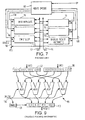
- Count the number of leading zeros in a register. Figure 6 shows a suitable arrangement for implementing the clz instruction, taking as an example the clz8 instruction applied to a 64-bit input register. The functional blocks are all 2-bit multiplexers, with successive bits of the input register (indicated as "bxx", wit b0 being the least significant bit and b63 the most significant bit) being applied as the control signals.
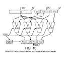
- add2p
- Add each respective S1[i] to S2[i] as 2's complement numbers producing R[i]. Overflow is ignored.
- sub2p
- Subtract each respective S2[i] from S1[i] as 2's complement numbers producing R[i]. Overflow is ignored.
- cmpe2p
- Compare each respective S1[i] with S2[i]. If they are equal, set R[i] to all ones; if they are different, set R[i] to zero.
- cmpne2p
- Compare each respective S1[i] with S2[i]. If they are not equal, set R[i] to all ones; if they are different, set R[i] to zero.
- cmpge2ps
- Compare each respective S1[i] with S2[i] as signed 2's complement numbers. If S1[i] is greater than or equal to S2[i] set R[i] to all ones; if S1[i] is less than S2[i] set R[i] to zero.
- mul2ps
- Multiply each respective S1[i] by S2[i] as signed 2's complement numbers setting R[i] to the least significant 16 bits of the full (32 bit) product.
- shl2p
- Shift each respective S1[i] left by S2 (which is not packed), setting R[i] to the result.
- shr2ps
- Shift each respective S1[i] right by S2 (which is not packed, setting R[i] to the result. The shift is signed, because the sign bit is duplicated when shifting.


Claims (12)
- A method for run-length encoding two or more data values, the method comprising:characterised by the steps ofloading the data values into storage by forming a first data string, the data string comprising a plurality of data sub-strings and each data sub-string representing at least one of the data values;
generating a second data string having a data sub-string corresponding to each data sub-string of the first data string, all the bits of each of the data sub-strings of the second data string having a first predetermined value if all the bits of the corresponding data sub-string of the first data string have a second predetermined value and having a third predetermined value if any of the bits of the corresponding data sub-string of the first data string has other than the second predetermined value;
starting from a predetermined end of the second data string, counting the number of consecutive bits of the second data string having the first predetermined value; and
dividing the said number by the number of bits in each data sub-string. - A method as claimed in claim 1, wherein the first predetermined value is zero.
- A method as claimed in claim 1 or 2, wherein all the data sub-strings have the same length.
- A method as claimed in any preceding claim, wherein the second predetermined value is zero.
- A method as claimed in any preceding claim, wherein all the data sub-strings are at least two bits long.
- A method as claimed in any preceding claim, wherein the data values are loaded into a computer store in which the data sub-strings are not individually addressable.
- A method as claimed in any preceding claim, wherein the step of generating the second data string is performed by executing an instruction to compare the first data string with a third data string all of whose bits are of the second predetermined value.
- A method as claimed in any preceding claim, further comprising the step of generating a fourth data string by masking the first data string with the second data string.
- A method as claimed in any preceding claim, wherein the step of dividing is performed by executing a bit shift.
- A data compression method comprising a method for run-length encoding as claimed in any preceding claim.
- A computer comprising:processing means for excuting a series of instructions;data memory for storing data strings, each comprising a plurality of data substrings; andprogram memory with stored therein said series of instructions, said series of instructions instructing said processing means to execute the method claimed in any preceding claim.
- A computer as claimed in claim 11, wherein the processing means includes dedicated apparatus for performing the step of generating the second data string.
Applications Claiming Priority (2)
| Application Number | Priority Date | Filing Date | Title |
|---|---|---|---|
| GBGB9727398.1A GB9727398D0 (en) | 1997-12-29 | 1997-12-29 | Run-length encoding |
| GB9727398 | 1997-12-29 |
Publications (2)
| Publication Number | Publication Date |
|---|---|
| EP0928100A1 EP0928100A1 (en) | 1999-07-07 |
| EP0928100B1 true EP0928100B1 (en) | 2003-03-19 |
Family
ID=10824264
Family Applications (1)
| Application Number | Title | Priority Date | Filing Date |
|---|---|---|---|
| EP98310007A Expired - Lifetime EP0928100B1 (en) | 1997-12-29 | 1998-12-07 | Run-length encoding |
Country Status (4)
| Country | Link |
|---|---|
| US (1) | US6737993B2 (en) |
| EP (1) | EP0928100B1 (en) |
| DE (1) | DE69812311D1 (en) |
| GB (1) | GB9727398D0 (en) |
Families Citing this family (12)
| Publication number | Priority date | Publication date | Assignee | Title |
|---|---|---|---|---|
| US7039106B2 (en) * | 2002-03-25 | 2006-05-02 | Intel Corporation | Processing digital data prior to compression |
| US7606847B2 (en) * | 2004-03-29 | 2009-10-20 | Vince Grolmusz | Dense and randomized storage and coding of information |
| US7327289B1 (en) | 2006-09-20 | 2008-02-05 | Intel Corporation | Data-modifying run length encoder to avoid data expansion |
| US8108361B2 (en) * | 2008-07-31 | 2012-01-31 | Microsoft Corporation | Efficient column based data encoding for large-scale data storage |
| EP2798478A4 (en) * | 2011-12-30 | 2016-12-21 | Intel Corp | Efficient zero-based decompression |
| US9459866B2 (en) * | 2011-12-30 | 2016-10-04 | Intel Corporation | Vector frequency compress instruction |
| US9160363B2 (en) * | 2014-02-27 | 2015-10-13 | Samsung Display Co., Ltd. | Run length encoding with non-sequential input |
| US10747819B2 (en) | 2018-04-20 | 2020-08-18 | International Business Machines Corporation | Rapid partial substring matching |
| US10782968B2 (en) * | 2018-08-23 | 2020-09-22 | International Business Machines Corporation | Rapid substring detection within a data element string |
| US10732972B2 (en) | 2018-08-23 | 2020-08-04 | International Business Machines Corporation | Non-overlapping substring detection within a data element string |
| US10996951B2 (en) | 2019-09-11 | 2021-05-04 | International Business Machines Corporation | Plausibility-driven fault detection in string termination logic for fast exact substring match |
| US11042371B2 (en) | 2019-09-11 | 2021-06-22 | International Business Machines Corporation | Plausability-driven fault detection in result logic and condition codes for fast exact substring match |
Citations (2)
| Publication number | Priority date | Publication date | Assignee | Title |
|---|---|---|---|---|
| WO1996017292A1 (en) * | 1994-12-02 | 1996-06-06 | Intel Corporation | Microprocessor with compare operation of composite operands |
| EP0744686A1 (en) * | 1995-05-17 | 1996-11-27 | STMicroelectronics Limited | Manipulation of data |
Family Cites Families (6)
| Publication number | Priority date | Publication date | Assignee | Title |
|---|---|---|---|---|
| US3935379A (en) * | 1974-05-09 | 1976-01-27 | General Dynamics Corporation | Method of and system for adaptive run length encoding of image representing digital information |
| US4494151A (en) * | 1979-07-02 | 1985-01-15 | Xerox Corporation | 4-Pixel run-length code for data compression |
| EP0071680B1 (en) * | 1981-08-07 | 1988-10-26 | International Business Machines Corporation | Data recording or transmission system using run length limited coding |
| JP3134424B2 (en) * | 1991-10-31 | 2001-02-13 | ソニー株式会社 | Variable length encoding method and apparatus |
| JP3210996B2 (en) * | 1993-07-30 | 2001-09-25 | 三菱電機株式会社 | High efficiency coding device and high efficiency decoding device |
| US5574448A (en) * | 1995-05-08 | 1996-11-12 | Quantum Corporation | Method and apparatus for encoding data with variable block lengths |
-
1997
- 1997-12-29 GB GBGB9727398.1A patent/GB9727398D0/en not_active Ceased
-
1998
- 1998-12-07 EP EP98310007A patent/EP0928100B1/en not_active Expired - Lifetime
- 1998-12-07 DE DE69812311T patent/DE69812311D1/en not_active Expired - Lifetime
-
2002
- 2002-05-10 US US10/143,542 patent/US6737993B2/en not_active Expired - Lifetime
Patent Citations (2)
| Publication number | Priority date | Publication date | Assignee | Title |
|---|---|---|---|---|
| WO1996017292A1 (en) * | 1994-12-02 | 1996-06-06 | Intel Corporation | Microprocessor with compare operation of composite operands |
| EP0744686A1 (en) * | 1995-05-17 | 1996-11-27 | STMicroelectronics Limited | Manipulation of data |
Also Published As
| Publication number | Publication date |
|---|---|
| GB9727398D0 (en) | 1998-02-25 |
| US20030137437A1 (en) | 2003-07-24 |
| EP0928100A1 (en) | 1999-07-07 |
| US6737993B2 (en) | 2004-05-18 |
| DE69812311D1 (en) | 2003-04-24 |
Similar Documents
| Publication | Publication Date | Title |
|---|---|---|
| US7289047B2 (en) | Decoding variable length codes while using optimal resources | |
| US7132963B2 (en) | Methods and apparatus for processing variable length coded data | |
| US6195026B1 (en) | MMX optimized data packing methodology for zero run length and variable length entropy encoding | |
| US7804903B2 (en) | Hardware-based CABAC decoder | |
| US6043765A (en) | Method and apparatus for performing a parallel speculative Huffman decoding using both partial and full decoders | |
| EP0928100B1 (en) | Run-length encoding | |
| KR100331136B1 (en) | A computer system performing an inverse cosine transfer function for use with multimedia information | |
| US6629115B1 (en) | Method and apparatus for manipulating vectored data | |
| JPH11505640A (en) | Bit slice table lookup digital convolution | |
| JPH07236143A (en) | High-speed digital signal decoding method | |
| WO2008002804A1 (en) | Hardware-based cabac decoder with parallel binary arithmetic decoding | |
| US5872965A (en) | System and method for performing multiway branches using a visual instruction set | |
| US7275147B2 (en) | Method and apparatus for data alignment and parsing in SIMD computer architecture | |
| KR100261374B1 (en) | Image processing device | |
| US6781529B1 (en) | Methods and apparatuses for variable length encoding | |
| US6574651B1 (en) | Method and apparatus for arithmetic operation on vectored data | |
| WO2010129684A1 (en) | Execution units for context adaptive binary arithmetic coding (cabac) | |
| US5642306A (en) | Method and apparatus for a single instruction multiple data early-out zero-skip multiplier | |
| US5689592A (en) | Parallel processing of digital signals in a single arithmetic/logic unit | |
| US6247112B1 (en) | Bit manipulation instructions | |
| US20030172254A1 (en) | Instructions for manipulating vectored data | |
| US6850566B2 (en) | Implementation of quantization for SIMD architecture | |
| EP0928113A1 (en) | Method and apparatus for data manipulation | |
| EP0928114B1 (en) | Video data decoding apparatus | |
| JP2002519957A (en) | Method and apparatus for processing a sign function |
Legal Events
| Date | Code | Title | Description |
|---|---|---|---|
| PUAI | Public reference made under article 153(3) epc to a published international application that has entered the european phase |
Free format text: ORIGINAL CODE: 0009012 |
|
| AK | Designated contracting states |
Kind code of ref document: A1 Designated state(s): DE FR GB IT |
|
| AX | Request for extension of the european patent |
Free format text: AL;LT;LV;MK;RO;SI |
|
| 17P | Request for examination filed |
Effective date: 19991221 |
|
| AKX | Designation fees paid |
Free format text: DE FR GB IT |
|
| 17Q | First examination report despatched |
Effective date: 20010824 |
|
| GRAG | Despatch of communication of intention to grant |
Free format text: ORIGINAL CODE: EPIDOS AGRA |
|
| GRAG | Despatch of communication of intention to grant |
Free format text: ORIGINAL CODE: EPIDOS AGRA |
|
| GRAH | Despatch of communication of intention to grant a patent |
Free format text: ORIGINAL CODE: EPIDOS IGRA |
|
| GRAH | Despatch of communication of intention to grant a patent |
Free format text: ORIGINAL CODE: EPIDOS IGRA |
|
| GRAA | (expected) grant |
Free format text: ORIGINAL CODE: 0009210 |
|
| AK | Designated contracting states |
Designated state(s): DE FR GB IT |
|
| PG25 | Lapsed in a contracting state [announced via postgrant information from national office to epo] |
Ref country code: IT Free format text: LAPSE BECAUSE OF FAILURE TO SUBMIT A TRANSLATION OF THE DESCRIPTION OR TO PAY THE FEE WITHIN THE PRESCRIBED TIME-LIMIT;WARNING: LAPSES OF ITALIAN PATENTS WITH EFFECTIVE DATE BEFORE 2007 MAY HAVE OCCURRED AT ANY TIME BEFORE 2007. THE CORRECT EFFECTIVE DATE MAY BE DIFFERENT FROM THE ONE RECORDED. Effective date: 20030319 Ref country code: FR Free format text: LAPSE BECAUSE OF FAILURE TO SUBMIT A TRANSLATION OF THE DESCRIPTION OR TO PAY THE FEE WITHIN THE PRESCRIBED TIME-LIMIT Effective date: 20030319 |
|
| REG | Reference to a national code |
Ref country code: GB Ref legal event code: FG4D |
|
| REF | Corresponds to: |
Ref document number: 69812311 Country of ref document: DE Date of ref document: 20030424 Kind code of ref document: P |
|
| PG25 | Lapsed in a contracting state [announced via postgrant information from national office to epo] |
Ref country code: DE Free format text: LAPSE BECAUSE OF FAILURE TO SUBMIT A TRANSLATION OF THE DESCRIPTION OR TO PAY THE FEE WITHIN THE PRESCRIBED TIME-LIMIT Effective date: 20030621 |
|
| PG25 | Lapsed in a contracting state [announced via postgrant information from national office to epo] |
Ref country code: GB Free format text: LAPSE BECAUSE OF NON-PAYMENT OF DUE FEES Effective date: 20031207 |
|
| PLBE | No opposition filed within time limit |
Free format text: ORIGINAL CODE: 0009261 |
|
| STAA | Information on the status of an ep patent application or granted ep patent |
Free format text: STATUS: NO OPPOSITION FILED WITHIN TIME LIMIT |
|
| EN | Fr: translation not filed | ||
| 26N | No opposition filed |
Effective date: 20031222 |
|
| GBPC | Gb: european patent ceased through non-payment of renewal fee |
Effective date: 20031207 |