EP0927902A2 - Vorrichtung zur Sonnenbeobachtung - Google Patents
Vorrichtung zur Sonnenbeobachtung Download PDFInfo
- Publication number
- EP0927902A2 EP0927902A2 EP99200248A EP99200248A EP0927902A2 EP 0927902 A2 EP0927902 A2 EP 0927902A2 EP 99200248 A EP99200248 A EP 99200248A EP 99200248 A EP99200248 A EP 99200248A EP 0927902 A2 EP0927902 A2 EP 0927902A2
- Authority
- EP
- European Patent Office
- Prior art keywords
- viewing
- light
- aperture
- objective
- reflection means
- Prior art date
- Legal status (The legal status is an assumption and is not a legal conclusion. Google has not performed a legal analysis and makes no representation as to the accuracy of the status listed.)
- Withdrawn
Links
Images

Classifications
-
- G—PHYSICS
- G02—OPTICS
- G02B—OPTICAL ELEMENTS, SYSTEMS OR APPARATUS
- G02B23/00—Telescopes, e.g. binoculars; Periscopes; Instruments for viewing the inside of hollow bodies; Viewfinders; Optical aiming or sighting devices
- G02B23/02—Telescopes, e.g. binoculars; Periscopes; Instruments for viewing the inside of hollow bodies; Viewfinders; Optical aiming or sighting devices involving prisms or mirrors
- G02B23/08—Periscopes
-
- G—PHYSICS
- G02—OPTICS
- G02B—OPTICAL ELEMENTS, SYSTEMS OR APPARATUS
- G02B17/00—Systems with reflecting surfaces, with or without refracting elements
- G02B17/02—Catoptric systems, e.g. image erecting and reversing system
-
- G—PHYSICS
- G02—OPTICS
- G02B—OPTICAL ELEMENTS, SYSTEMS OR APPARATUS
- G02B27/00—Optical systems or apparatus not provided for by any of the groups G02B1/00 - G02B26/00, G02B30/00
- G02B27/02—Viewing or reading apparatus
- G02B27/022—Viewing apparatus
-
- G—PHYSICS
- G02—OPTICS
- G02B—OPTICAL ELEMENTS, SYSTEMS OR APPARATUS
- G02B5/00—Optical elements other than lenses
- G02B5/20—Filters
- G02B5/205—Neutral density filters
Definitions
- This invention relates to means for enabling persons to make direct visual observations of the sun, in particular during partial and annular eclipses, without damage to the eyes.
- a device for viewing the sun comprises a body member defining a housing including an objective aperture and a viewing aperture, the housing containing optical elements consisting only of light-absorbing reflection means arranged to define a light pathway between said objective and viewing apertures the respective axes or planes of which subtend between them an angle, whereby total light transmittance is attenuated to an extent such as to enable the sun to be viewed with safety.
- the optical elements are contained entirely within the housing and the viewing aperture comprises a slot having internal walls parallel with the light pathway therethrough, although the viewing aperture may be of more conventional cylindrical construction, for viewing with one eye only, and optionally includes a pivoted or hinged element for protection of the other eye, when in the extended position, from glare.
- the plate may comprise a resilient cup-shaped formation for fitting to the face around the other eye, to provide more effective exclusion of light and correspondingly to allow the image viewed by the one eye to be more clearly seen.
- the wall of the slot or of the cylinder may extend within the housing close to the nearest of the optical elements associated with the viewing aperture.
- the subtended angle may be an obtuse angle but is preferably at or close to a right angle, whereby even with the sun at its maximum angle of elevation it can still be viewed with the user adopting a level or in most instances a slightly lowered head position.
- the optical elements may comprise any transparent material capable of being formed with an optically-flat reflecting surface and capable of light absorption such that the total absorption results in residual transmission within the accepted limits.
- the material may comprise glass or a plastics material such as acrylic and preferably has a refractive index of a least 1.4, preferably approximately 1.5 with an upper limit of about 1.6 to 1.7.
- the material preferably contains dye to enhance the light-absorption properties.
- a material having a refractive index of 1.5 will reflect on average about 4% of the light incident upon it, including infra-red and ultra-violet light as well as visible.
- the reflector means may be constituted by plane elements, prisms or a combination thereof.
- the image viewed by the observer through the viewing aperture is upright, which implies two reflection means or a multiple of two.
- two reflection means could be contemplated, disposed at a mutual angle of for example 45° to divert the light pathway through 90° without inversion
- the arrangement of the respective viewing and objective apertures in relation to the remainder of the housing is preferably such that there is no direct light pathway therebetween and furthermore the internal disposition of the reflection means should preferably be such that the breakage or dislodgement of any one reflection means should not result in an alternative light pathway being created between the viewing and objective apertures, since any such alternative light pathway would comprise less light-absorption capability.
- the internal surfaces of the housing should preferably be coloured black or other light-absorbing colour.
- the body member may incorporate means for attachment to a tripod or means for gripping railings or other suitable supports, thereby enabling binoculars or other image-enhancing means to be used to view the image in the viewing aperture.
- the invention provides a method for observation of the sun, the method comprising pointing the objective aperture of a device as hereinbefore described at the sun and viewing the image thereof though the viewing aperture, the light rays incident through the objective aperture following a light-absorbing reflected pathway to the viewing aperture.
- the device shown generally at 10 has a rectangular box-shaped body 11 having a recessed wall 12 at one end which extends only part-way across the end, to leave a horizontal rectangular slot 13 for restricted access of light to the interior of the body.
- the upper face 14 is formed, towards the end remote from wall 12, with another rectangular slot 15 which is surrounded by an upstanding wall or combing 16 the purpose of which is to restrict access of peripheral light to the interior of the body except in a direction generally at a right angle to the face 14.
- the slot 13 in use constitutes the objective aperture and slot 15 constitutes the viewing aperture and the respective axial planes through the apertures - that is, the planes which light rays pass through in use and which are substantially normal to the respective slots - are at a right angle to each other, whereby a user observing the sun can point the objective aperture at an upward angle towards the sun and yet still see the image through the viewing aperture with a head-down posture, as shown in Figure 2.
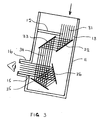
- the incident light 31 entering the body or housing 11 through slot 13 falls initially on glass plate 32 set at 45° and is reflected (with some absorbance) to parallel-mounted glass plate 33.
- the plates 32 and 33 act as a couple and the non-absorbed reflected light rays 34 are parallel but displaced laterally compared with light rays 31. It will be understood that plates 32 and 33 need not be set at 45°; they could be set at another angle if it was desired to position one or both of them at a different location within the housing, for example to avoid risk of an undesired secondary reflectance pathway between the slots on the event of damage to a plate occurring, or to reduce or increase the total attenuation of the transmitted light.
- the rays 34 are then incident upon plates 35 and 36 mounted at a 45° angle between them. Plates 35, 36 exist as a further couple to reflect the rays with further absorbance through 90° so that they are normal to and in alignment with slot 15 for viewing by the user.
- Total light transmittance though the device as described with reference to the drawings is approximately 0.0003% if glass of refractive index 1.5 is used for the reflecting plates, which makes the device both safe and comfortable for use in viewing the sun.
Landscapes
- Physics & Mathematics (AREA)
- General Physics & Mathematics (AREA)
- Optics & Photonics (AREA)
- Astronomy & Astrophysics (AREA)
- Investigating Or Analysing Materials By Optical Means (AREA)
- Microscoopes, Condenser (AREA)
- Optical Elements Other Than Lenses (AREA)
Priority Applications (1)
| Application Number | Priority Date | Filing Date | Title |
|---|---|---|---|
| CA 2281290 CA2281290A1 (en) | 1998-08-27 | 1999-08-27 | Sun-observation device |
Applications Claiming Priority (4)
| Application Number | Priority Date | Filing Date | Title |
|---|---|---|---|
| GB9818556 | 1998-08-27 | ||
| GBGB9818556.4A GB9818556D0 (en) | 1998-08-27 | 1998-08-27 | A device for the safe observation of the sun |
| GB9822212A GB2327282B (en) | 1998-08-27 | 1998-10-12 | Sun-observation device |
| GB9822212 | 1998-10-12 |
Publications (2)
| Publication Number | Publication Date |
|---|---|
| EP0927902A2 true EP0927902A2 (de) | 1999-07-07 |
| EP0927902A3 EP0927902A3 (de) | 1999-07-28 |
Family
ID=26314260
Family Applications (1)
| Application Number | Title | Priority Date | Filing Date |
|---|---|---|---|
| EP99200248A Withdrawn EP0927902A3 (de) | 1998-08-27 | 1999-01-29 | Vorrichtung zur Sonnenbeobachtung |
Country Status (1)
| Country | Link |
|---|---|
| EP (1) | EP0927902A3 (de) |
Cited By (2)
| Publication number | Priority date | Publication date | Assignee | Title |
|---|---|---|---|---|
| FR2812951A1 (fr) * | 2000-08-14 | 2002-02-15 | Jean Gay | Dispositif optique qui a pour but de delivrer sur un ecran diffusant une image du soleil par retroprojection |
| WO2004008224A1 (fr) * | 2002-07-16 | 2004-01-22 | Light Tec | Dispositif d'observation de l'image retro-projetee du soleil sur un ecran |
Family Cites Families (1)
| Publication number | Priority date | Publication date | Assignee | Title |
|---|---|---|---|---|
| GB2308676A (en) * | 1995-12-28 | 1997-07-02 | Stanley Bell | Terrestrial telescope having four mirrors |
-
1999
- 1999-01-29 EP EP99200248A patent/EP0927902A3/de not_active Withdrawn
Cited By (3)
| Publication number | Priority date | Publication date | Assignee | Title |
|---|---|---|---|---|
| FR2812951A1 (fr) * | 2000-08-14 | 2002-02-15 | Jean Gay | Dispositif optique qui a pour but de delivrer sur un ecran diffusant une image du soleil par retroprojection |
| WO2004008224A1 (fr) * | 2002-07-16 | 2004-01-22 | Light Tec | Dispositif d'observation de l'image retro-projetee du soleil sur un ecran |
| FR2842613A1 (fr) * | 2002-07-16 | 2004-01-23 | Light Tec | Dispositif d'observation de l'image retro-projetee du soleil sur un ecran |
Also Published As
| Publication number | Publication date |
|---|---|
| EP0927902A3 (de) | 1999-07-28 |
Similar Documents
| Publication | Publication Date | Title |
|---|---|---|
| CA3010025C (en) | Ophthalmic lens | |
| AU2015355331B2 (en) | Vision-protecting filter lens | |
| EP2373268A1 (de) | Optischer filter zur selektiven blockade von licht | |
| EP2859867A1 (de) | Laserschützende Vorrichtung mit reflektierendem Filter auf nichtabsorbierenden und absorbierenden Substraten | |
| US5680195A (en) | Vision enhancing assembly | |
| JPH10307263A5 (de) | ||
| US4879167A (en) | Real time holographic filter using nonlinear optical materials | |
| EP0927902A2 (de) | Vorrichtung zur Sonnenbeobachtung | |
| WO1992015039A1 (en) | Telescopic spectacles with coaxial illumination | |
| GB2327282A (en) | Sun observation device | |
| US6483647B2 (en) | Night vision device | |
| EP0215118A1 (de) | Kompakte nachtsichtbrille. | |
| CA2281290A1 (en) | Sun-observation device | |
| US20020039236A1 (en) | Methods for reflection reductions | |
| Marsh | Observing the sun in safety | |
| CN210142234U (zh) | 一种太阳导标安全过滤器盖 | |
| EA011843B1 (ru) | Устройство обнаружения оптоэлектронных объектов (варианты) | |
| KR101427287B1 (ko) | 잠망경식 외시경장치 | |
| CN110058397A (zh) | 一种太阳导标安全过滤器盖 | |
| RU19423U1 (ru) | Перископическое устройство для дневного/ночного наблюдения | |
| CA1163844A (en) | Curtain for shrouding welding operations | |
| CA1153593A (en) | Curtain for shrouding welding operations | |
| CN210605054U (zh) | 一种防划痕cab镜用复合偏光膜 | |
| Clark | Polarizing sunglasses and possible eye hazards of transmitted radiation | |
| Kloske et al. | Modern battlefield and new materials for eyes protection |
Legal Events
| Date | Code | Title | Description |
|---|---|---|---|
| PUAI | Public reference made under article 153(3) epc to a published international application that has entered the european phase |
Free format text: ORIGINAL CODE: 0009012 |
|
| PUAL | Search report despatched |
Free format text: ORIGINAL CODE: 0009013 |
|
| AK | Designated contracting states |
Kind code of ref document: A2 Designated state(s): AT BE CH CY DE DK ES FI FR GB GR IE IT LI LU MC NL PT SE |
|
| AX | Request for extension of the european patent |
Free format text: AL;LT;LV;MK;RO;SI |
|
| AK | Designated contracting states |
Kind code of ref document: A3 Designated state(s): AT BE CH CY DE DK ES FI FR GB GR IE IT LI LU MC NL PT SE |
|
| AX | Request for extension of the european patent |
Free format text: AL;LT;LV;MK;RO;SI |
|
| AKX | Designation fees paid | ||
| REG | Reference to a national code |
Ref country code: DE Ref legal event code: 8566 |
|
| STAA | Information on the status of an ep patent application or granted ep patent |
Free format text: STATUS: THE APPLICATION IS DEEMED TO BE WITHDRAWN |
|
| 18D | Application deemed to be withdrawn |
Effective date: 20000129 |