EP0927872B1 - Speed and position sensors for rotating shafts - Google Patents
Speed and position sensors for rotating shafts Download PDFInfo
- Publication number
- EP0927872B1 EP0927872B1 EP98403147A EP98403147A EP0927872B1 EP 0927872 B1 EP0927872 B1 EP 0927872B1 EP 98403147 A EP98403147 A EP 98403147A EP 98403147 A EP98403147 A EP 98403147A EP 0927872 B1 EP0927872 B1 EP 0927872B1
- Authority
- EP
- European Patent Office
- Prior art keywords
- encoder
- sensor
- magnetic
- sensitive elements
- fact
- Prior art date
- Legal status (The legal status is an assumption and is not a legal conclusion. Google has not performed a legal analysis and makes no representation as to the accuracy of the status listed.)
- Expired - Lifetime
Links
- 230000007704 transition Effects 0.000 claims description 67
- 230000010363 phase shift Effects 0.000 claims description 19
- 238000005259 measurement Methods 0.000 claims description 14
- 230000005355 Hall effect Effects 0.000 claims description 4
- 238000000034 method Methods 0.000 claims description 4
- 238000013461 design Methods 0.000 description 8
- 230000008901 benefit Effects 0.000 description 6
- 238000010276 construction Methods 0.000 description 6
- 238000005516 engineering process Methods 0.000 description 2
- 230000005415 magnetization Effects 0.000 description 2
- 238000004519 manufacturing process Methods 0.000 description 2
- 238000004377 microelectronic Methods 0.000 description 2
- 241000861223 Issus Species 0.000 description 1
- BGPVFRJUHWVFKM-UHFFFAOYSA-N N1=C2C=CC=CC2=[N+]([O-])C1(CC1)CCC21N=C1C=CC=CC1=[N+]2[O-] Chemical compound N1=C2C=CC=CC2=[N+]([O-])C1(CC1)CCC21N=C1C=CC=CC1=[N+]2[O-] BGPVFRJUHWVFKM-UHFFFAOYSA-N 0.000 description 1
- 239000000470 constituent Substances 0.000 description 1
- 238000012937 correction Methods 0.000 description 1
- 230000001815 facial effect Effects 0.000 description 1
- 239000000463 material Substances 0.000 description 1
- 230000005405 multipole Effects 0.000 description 1
- 238000012545 processing Methods 0.000 description 1
- 238000006467 substitution reaction Methods 0.000 description 1
Images


Classifications
-
- G—PHYSICS
- G01—MEASURING; TESTING
- G01D—MEASURING NOT SPECIALLY ADAPTED FOR A SPECIFIC VARIABLE; ARRANGEMENTS FOR MEASURING TWO OR MORE VARIABLES NOT COVERED IN A SINGLE OTHER SUBCLASS; TARIFF METERING APPARATUS; MEASURING OR TESTING NOT OTHERWISE PROVIDED FOR
- G01D5/00—Mechanical means for transferring the output of a sensing member; Means for converting the output of a sensing member to another variable where the form or nature of the sensing member does not constrain the means for converting; Transducers not specially adapted for a specific variable
- G01D5/12—Mechanical means for transferring the output of a sensing member; Means for converting the output of a sensing member to another variable where the form or nature of the sensing member does not constrain the means for converting; Transducers not specially adapted for a specific variable using electric or magnetic means
- G01D5/14—Mechanical means for transferring the output of a sensing member; Means for converting the output of a sensing member to another variable where the form or nature of the sensing member does not constrain the means for converting; Transducers not specially adapted for a specific variable using electric or magnetic means influencing the magnitude of a current or voltage
- G01D5/142—Mechanical means for transferring the output of a sensing member; Means for converting the output of a sensing member to another variable where the form or nature of the sensing member does not constrain the means for converting; Transducers not specially adapted for a specific variable using electric or magnetic means influencing the magnitude of a current or voltage using Hall-effect devices
- G01D5/145—Mechanical means for transferring the output of a sensing member; Means for converting the output of a sensing member to another variable where the form or nature of the sensing member does not constrain the means for converting; Transducers not specially adapted for a specific variable using electric or magnetic means influencing the magnitude of a current or voltage using Hall-effect devices influenced by the relative movement between the Hall device and magnetic fields
Definitions
- the present invention relates to a device for relative position and speed measurement of a shaft mobile in rotation, composed of a magnetic encoder annular, with multipolar magnetization, integral and concentric of the shaft, and a sensor at least two separate sensitive elements, Hall effect or magnetoristance, linked to a fixed frame.
- the originality of the invention relates more particularly to new designs of multipole encoders which simplify the final assembly of measuring devices and using a type sensor unique against encoders with characteristics of different magnetization.
- signals from sensitive elements are shaped sinusoidal, it is also known to be able to adjust quadrature by signal processing appropriate electronics.
- a provision in mounting concentrically and in solidarity with the rotating shaft, a disc-shaped encoder annular, magnetized on one of its faces.
- the magnetic transitions defined between the sectors of North polarity and South polarity sectors are generally carried by spokes of the disc or the encoder ring.
- the multipolar magnet is therefore consisting of a number equal to 2m circular sectors or poles of angle ⁇ / m, of alternating polarities opposite, which determine m sector periods of 2 ⁇ / m angular value.
- d 2R * sin [(2n + 1) * ⁇ / 4m] in which: d is the distance between the centers of the sensitive elements of the sensor, R is the reading radius of the encoder where the sensitive elements are placed, and n a negative, zero or positive integer which allows to fix the quadrature states.
- the first problem resulting from this provision is that with each new conception of a measuring device modifying, i.e. the number of encoder periods, i.e. the position of the sensor on the reading radius R, it is necessary to create a new sensor with two sensitive elements suitably spaced to ensure the condition of squaring, which increases manufacturing costs.
- the appropriate manufacturing technologies are preferably those that implement processes by carrying sensitive elements into discrete components on a support, the placement details of which are insufficient and do not allow to overcome the obligation of an adjustment at the end of assembly of each measuring device built.
- the purpose of the present invention is to overcome these disadvantages by proposing a new device rotation speed and position measurement, which comprises on the one hand a sensor carrying two elements, sensitive to Hall effect or magnetoresistance, to precise predetermined spacing, linked to a fixed frame and on the other hand a multipolar encoder, integral with the rotating part and centered on the axis of rotation, realized in such a way that the sensitive elements of the sensor always have the same relative phase shift in the magnetic field of the encoder, when said sensor is moved along an axis passing through the centers of sensitive elements.
- the invention also relates to the conditions using the same sensor in front of encoders different dimensions or that have a number different from magnetic periods.
- This character universality gives the manufacturer the possibility of realize the sensor in integrated circuit by known micro-electronic technologies, which can possibly, with a view to miniaturization, drive to tighten the elements sensitive to a value less than that which corresponds to the placement in quadrature of the sensor in the magnetic field of the encoder and then orthogonalize the signals from sensitive elements by simple electronic means known; the deviation from exact squaring being of value constant, electronic correction remains constant for all coders produced and used in conditions of the invention.
- the invention also relates to several variants of realization of circular multipolar encoders or annulars, including the length of the magnetic period, measured along a previously defined axis, is constant, regardless of the number of periods in the magnetic division per encoder revolution and whatever are the dimensions of said encoder.
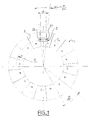
- Figure 1 shows a measuring device comprising a circular encoder of annular shape 1, according to the prior art, comprising m periods North-South magnetic, concentrically united to a rotating shaft not shown facing a sensor 2 comprising two sensitive elements 21 and 22, the centers are distant by a value d.
- the two sensitive elements of the sensor 21 and 22, both located on the same circle C L of reading radius R, are in geometric quadrature in the magnetic field of the encoder if the following relation is verified: d 2R * sin [(2n + 1) * ⁇ / 4m] n being a negative, zero or positive integer.
- the distance d can take at most m distinct values for a given reading radius R.
- any deviation from the values of d and R set by the designer according to this relation entailed deviations from quadrature therefore requires adjustment after assembly of the device.
- the design of a new device comprising an encoder with a number different from magnetic poles usually leads to design also a new sensor with a distance d adapted.
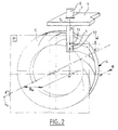
- FIG. 2 represents a measuring device according to the invention, comprising a sensor 5, produced in an integrated circuit by micro-electronic means for example, which has two elements 51 and 52 sensitive to the magnetic field, the distance d between their centers is fixed at a single and constant value and whose position of the axis joining said centers is known. It further comprises a magnetic encoder 4 concentric and integral with the movable shaft in rotation, not shown, and with an axis of rotation ⁇ R.
- the sensor 5 is mounted in a plane P parallel to the magnetized face 6 of the encoder 4, so that the sensitive elements 51 and 52 are opposite the magnetic pattern of the encoder at an air gap distance e.
- the axis ⁇ c of the centers of the sensitive elements belonging to this plane P is located at a distance R 0 from the axis of rotation ⁇ R of the device.
- the axis ⁇ c is the axis on which the magnetic pattern of the encoder 4 is read by each of the sensitive elements 51 and 52.
- the distance d between the centers of the two sensitive elements is chosen to be compatible with the embodiment of the sensor .
- the axis ⁇ c is the axis on which the magnetic pattern of the encoder 4 is read by each of the sensitive elements 51 and 52.
- the spacing d being chosen, the quadrature situation or a phase shift situation of constant value is obtained whatever the position of the sensor holder 8 moving on the axis ⁇ c provided that the sensitive elements 51 and 52 both remain opposite the magnetic pattern of the encoder 4.
- the annular encoder 4 made of one of the constituent materials of the permanent magnets known to those skilled in the art, is magnetized on one of its faces 6, according to a succession in rotationally scrollable North and South magnetic patterns constituting m magnetic periods.
- one of the magnetic transitions separating two poles of opposite polarities is represented by one or the other of the systems of equations in polar coordinates ( ⁇ , ⁇ ): or
- the set of magnetic transitions of the encoder is defined by 2m successive rotations of angle ⁇ / m from the first magnetic transition from the center of the encoder giving 2m transitions or m periods magnetic.
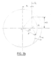
- FIG. 3a represents the plot according to the invention of a magnetic transition 10 between two North and South poles on an encoder 4 with center O.
- the axis ⁇ c located at a distance R o from the center O intersects the axis Oz, over which the distance R o at point X 'is measured.
- the point X ′ of the axis Oz is the origin of the magnetic transition 10 in the form of a spiral, which extends to the outer limit of the encoder.
- a point of the transition 10 is defined by its polar coordinates ( ⁇ , ⁇ ) which are on the one hand the module ⁇ and on the other hand the angle ⁇ of the origin Oz of the phase defined by the following relationships: in which, the quantity a ⁇ is carried by the axis ⁇ c from the origin X ', a is a constant calculated as a function of the distance d between the sensitive centers of the sensor and the number of magnetic periods of the encoder, ⁇ is the angle of rotation in the direct direction around the center O of the encoder 4 which generates, from the point on the axis ⁇ c of ordinate a ⁇ , the corresponding point of the transition 10 phase shifted by the angle ⁇ relative to originally.
- FIG. 3b represents the layout according to the invention of a magnetic transition 12 between two North and South poles on an encoder 4 responding to the relationships in polar coordinates ( ⁇ , ⁇ ) as follows: with a rotation of opposite direction of angle - ⁇ of the point of ordinate a ⁇ belonging to the axis ⁇ c , to generate the corresponding point of the transition 12.
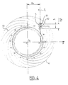
- FIG. 4 represents a first embodiment a magnetic encoder according to the invention, for which the layout of all the transitions between the poles magnetic north and south which are obtained by rotations, around the center O of the encoder, of the transition 10 as described in FIG. 3a. Each transition is deduced from the transition immediately consecutive by a rotation of angle ⁇ / m.
- the succession of these transitions 10 defines a succession of 2m North or South poles of the encoder magnet 4.
- the axis ⁇ c of origin X 'located on the axis Oz, at a distance R o from the center O of the encoder 4 intercepts the succession of transitions 10 according to a constant step equal to ⁇ a / m, while the circumferential step is by construction equal to ⁇ / m.
- the sensor 5 is placed so that the centers of the sensitive elements 51 and 52, distant from d, are on the axis ⁇ c .
- the signals from the sensitive elements 51 and 52 remain in constant phase shift, the value of which is solely a function of the relative value of the distance d, chosen as the distance separating the centers sensitive elements of the sensor, at the value of the pitch ⁇ a / m of the encoder measured on the axis ⁇ c .
- This phase shift of the signals from elements 51 and 52 also remains constant when the encoder rotates around its axis O.
- FIG. 5 represents a second embodiment of a magnetic coder according to the invention, for which the plot of all the magnetic transitions between the poles obtained by rotations, around the center O of the coder, of the transition 12 as described in Figure 3b.
- Each transition is deduced from the neighboring transition by a rotation of angle ⁇ / m.
- the succession of these transitions defines a succession of m periods or 2m North or South poles of the encoder magnet.
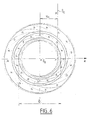
- FIG. 6 shows that, from the plot of FIG. 4, it is possible to produce an infinite number of annular encoders of different diameters and / or width having the advantages described above.
- the two conditions to be achieved are firstly that the internal diameter ⁇ i of the chosen encoder is not less than twice the distance R o between the two axes ⁇ c and ⁇ R and secondly that the centers of the sensitive elements of the sensor are located on the axis ⁇ c both facing the encoder.
- the spiral transitions can be extended beyond the layout, necessarily limited, of this figure without losing the advantages of the invention.
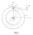
- FIG. 7 represents another nonlimiting example of a multipolar coder 4, the magnetic spiral transitions of which are defined according to one of the preceding relationships ⁇ and ⁇ , with the distance R o zero.
- the axis ⁇ c on which the centers of the sensitive elements of the sensor are located passes through the center O of the coder and intercepts the succession of transitions according to a constant step equal to ⁇ a / m, while the circumferential step is by construction equal to ⁇ / m.
- the two sensitive elements 51 and 52, distant from d, from sensor 5 therefore operate in the same signal phase shift as in the previous examples.
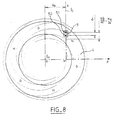
- the axis ⁇ c of origin X 'located on the axis Oz at a distance R o from the center of the encoder 4 passing through the centers of the sensitive elements 51 and 52 and of the sensor 5 intercepts the succession of transitions according to an equal constant pitch at ⁇ b / m ' ⁇ a / m, while the circumferential step is by construction equal to ⁇ / m'.
- FIGS. 4, 5, 6, 7 and 8 show an essential characteristic of the invention, according to which a single sensor made up of two sensitive elements, whose centers are distant by a value d, makes it possible to construct any sensor device when associated with annular encoders whose magnetized face shows an alternation of 2m North and South poles with circumferential scrolling, i.e. m magnetic periods, provided that the transitions between the poles respond, in polar coordinates, to the either of the following systems of equations: or : and that each of the transitions of an encoder is deduced from the immediately consecutive transition by a rotation of angle ⁇ / m relative to the center of the encoder.
- the half axis ⁇ c of origin X 'corresponding to its intersection in facial projection with the axis Oz which is the origin of the phases, located at a distance R o from the center of the encoder, carries the centers of the two sensitive elements of the sensor in any position opposite the encoder whose internal diameter is at least equal to 2 R o .
- the value of R o which depends on the choice of the designer can take any value from the zero value.
- Figure 9 shows another design of the device measurement where the phase shift of the output signals of sensitive elements 51 and 52 of sensor 5 is different of squaring.
- This choice can be made for example to allow a simplification of the realization of the encoder 4 or greater miniaturization of the sensor 5, by reducing the distance d from the centers of sensitive elements 51 and 52.
- the value of the phase shift chosen can be unified with all designs of speed sensor devices, and then it's possible to also provide a unified treatment of 5 sensor signals and thus maintain the benefit of the existence of a single sensor 5 for all designs of speed sensing devices or position.
- FIG. 10 represents, for an annular encoder 13 of small width, a possibility of simplification which consists in replacing the magnetic transition between two North and South poles in arc of spiral by a magnetic transition in arc of circle 14 of radius r, centered on the center of curvature O 'of point A of the spiral 15, located at the average diameter ⁇ m of the encoder.
- the means for calculating this radius of curvature and the position of the center of curvature are known.
- Another possibility is to use a circular arc transition 14, in substitution for the spiral transition 15 for its part between the internal circumference C i and the external circumference C e of the encoder, which consists in choosing the circular arc closest to the spiral axis by a method of minimizing the average of the quadratic distances of the two plots.
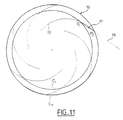
- FIG. 11 represents another simplified embodiment of an annular encoder 16 of small width which consists in replacing the magnetic transition between two North and South poles 19 in a spiral arc by a linear magnetic transition 17.
- the line 18 defining the position of the magnetic transition 17 can be either tangent to the spiral at mid-radius of the encoder 16, or secant passing through the two points P 1 and P 2 of intersection of the spiral with the inner circumferences C i and outer C e of the coding ring 16.
- the straight line 18 can also be the secant with a spiral arc, the position of which minimizes the mean of the quadratic differences in distance between the spiral and the straight line over the width of the annular magnet.
Landscapes
- Physics & Mathematics (AREA)
- General Physics & Mathematics (AREA)
- Transmission And Conversion Of Sensor Element Output (AREA)
Description
La présente invention est relative à un dispositif de mesure de position relative et de vitesse d'un arbre mobile en rotation, composé d'un codeur magnétique annulaire, à aimantation multipolaire, solidaire et concentrique de l'arbre, et d'un capteur à au moins deux éléments sensibles distincts, à effet Hall ou à magnétoristance, lié à un bâti fixe. L'originalité de l'invention est plus particulièrement relative à de nouvelles conceptions des codeurs multipolaires qui permettent de simplifier l'assemblage final des dispositifs de mesure et d'utiliser un capteur de type unique face à des codeurs à caractéristiques de magnétisation différentes.The present invention relates to a device for relative position and speed measurement of a shaft mobile in rotation, composed of a magnetic encoder annular, with multipolar magnetization, integral and concentric of the shaft, and a sensor at least two separate sensitive elements, Hall effect or magnetoristance, linked to a fixed frame. The originality of the invention relates more particularly to new designs of multipole encoders which simplify the final assembly of measuring devices and using a type sensor unique against encoders with characteristics of different magnetization.
Il est connu de mesurer la vitesse ou la position d'un mobile à l'aide d'un capteur à deux éléments sensibles disposés en face d'un codeur magnétique multipolaire. Généralement, on règle la position géométrique des deux éléments sensibles pour que leurs centres soient en quadrature dans le champ magnétique alternatif ou sinusoïdal de l'aimant. Cette situation est obtenue lorsque la distance entre les centres des éléments sensibles correspond à un nombre impair de quart de période magnétique du codeur. Les signaux électriques issus des éléments sensibles sont alors en quadrature de phase.It is known to measure the speed or the position of a mobile using a sensor with two sensitive elements arranged in front of a multipolar magnetic encoder. Generally, we adjust the geometric position of the two sensitive elements so that their centers are in quadrature in the alternating magnetic field or sine wave of the magnet. This situation is obtained when the distance between the centers of the elements sensitive corresponds to an odd number of quarter of magnetic period of the encoder. Electrical signals from the sensitive elements are then in quadrature phase.
Lorsque, sur un dispositif non géométriquement réglé, les signaux issus des éléments sensibles sont de forme sinusoïdale, il est également connu de pouvoir les régler en quadrature par un traitement de signal électronique approprié.When, on a non-geometrically adjusted device, signals from sensitive elements are shaped sinusoidal, it is also known to be able to adjust quadrature by signal processing appropriate electronics.
Dans le cas d'une mesure en rotation, une disposition consiste à monter de façon concentrique et solidaire à l'arbre tournant, un codeur en forme de disque annulaire, aimanté sur l'une de ses faces. Les transitions magnétiques définies entre les secteurs de polarité Nord et les secteurs de polarité Sud sont généralement portés par des rayons du disque ou de l'anneau codeur. L'aimant multipolaire est de ce fait constitué d'un nombre égal à 2m secteurs circulaires ou pôles d'angle π/m, de polarités alternativement opposées, qui déterminent m périodes sectorielles de 2π/m de valeur angulaire.In the case of a measurement in rotation, a provision consists in mounting concentrically and in solidarity with the rotating shaft, a disc-shaped encoder annular, magnetized on one of its faces. The magnetic transitions defined between the sectors of North polarity and South polarity sectors are generally carried by spokes of the disc or the encoder ring. The multipolar magnet is therefore consisting of a number equal to 2m circular sectors or poles of angle π / m, of alternating polarities opposite, which determine m sector periods of 2π / m angular value.
Le réglage géométrique en quadrature dans le champ
magnétique des éléments sensibles du capteur nécessite
que la relation dimensionnelle suivante soit vérifiée:
R est le rayon de lecture du codeur où sont placés les
éléments sensibles, et
n un nombre entier négatif, nul ou positif qui permet
de fixer les états de quadrature.The geometric quadrature adjustment in the magnetic field of the sensitive elements of the sensor requires that the following dimensional relationship be verified:
R is the reading radius of the encoder where the sensitive elements are placed, and
n a negative, zero or positive integer which allows to fix the quadrature states.
Cette égalité exprime qu'à un état de quadrature donné, soit un quart, trois quarts ou cinq quarts de période par exemple, et pour un nombre de périodes m du codeur magnétique choisi, il existe une relation univoque entre la distance d et le rayon de lecture R. This equality expresses that at a given quadrature state, either a quarter, three quarters or five quarters of a period for example, and for a number of periods m of the coder magnetic choice, there is a unique relationship between distance d and reading radius R.
Le premier problème résultant de cette disposition vient de ce qu'à chaque nouvelle conception d'un dispositif de mesure modifiant, soit le nombre de périodes du codeur, soit la position du capteur sur le rayon de lecture R, il est nécessaire de créer un nouveau capteur à deux éléments sensibles convenablement espacés pour assurer l'état de quadrature, ce qui augmente les coûts de fabrication. Les technologies de fabrication adaptées sont de préférence celles qui mettent en oeuvre des procédés par reports d'éléments sensibles en composants discrets sur un support, dont les précisions de placement sont insuffisantes et ne permettent pas de s'affranchir de l'obligation d'un réglage en fin d'assemblage de chaque dispositif de mesure construit.The first problem resulting from this provision is that with each new conception of a measuring device modifying, i.e. the number of encoder periods, i.e. the position of the sensor on the reading radius R, it is necessary to create a new sensor with two sensitive elements suitably spaced to ensure the condition of squaring, which increases manufacturing costs. The appropriate manufacturing technologies are preferably those that implement processes by carrying sensitive elements into discrete components on a support, the placement details of which are insufficient and do not allow to overcome the obligation of an adjustment at the end of assembly of each measuring device built.
Un autre problème résultant de cette disposition vient de ce que la fonction de bâti servant de support du capteur, est généralement assurée par des pièces de faible précision d'exécution, ce qui entraíne une imprécision de position du capteur sur le rayon de lecture du codeur et donc une imprécision de l'état de quadrature des signaux, si un réglage de chaque dispositif de mesure n'est pas réalisé lors de l'assemblage final.Another problem resulting from this provision comes that the function of the frame serving as a support for the sensor, is generally ensured by pieces of poor execution accuracy, which results in inaccuracy of position of the sensor on the radius of reading of the encoder and therefore an imprecision of the state of squaring the signals, if one setting of each measuring device is not produced during final assembly.
Le but de la présente invention est de pallier ces inconvénients en proposant un nouveau dispositif de mesure de vitesse de rotation et de position, qui comprend d'une part un capteur portant deux éléments, sensibles à effet Hall ou à magnétorésistance, à écartement précis prédéterminé, lié à un bâti fixe et d'autre part un codeur multipolaire, solidaire de la partie tournante et centré sur l'axe de rotation, réalisé de telle façon que les éléments sensibles du capteur présentent toujours le même déphasage relatif dans le champ magnétique du codeur, lorsque ledit capteur est déplacé selon un axe passant par les centres des éléments sensibles.The purpose of the present invention is to overcome these disadvantages by proposing a new device rotation speed and position measurement, which comprises on the one hand a sensor carrying two elements, sensitive to Hall effect or magnetoresistance, to precise predetermined spacing, linked to a fixed frame and on the other hand a multipolar encoder, integral with the rotating part and centered on the axis of rotation, realized in such a way that the sensitive elements of the sensor always have the same relative phase shift in the magnetic field of the encoder, when said sensor is moved along an axis passing through the centers of sensitive elements.
Pour cela l'objet de l'invention est un dispositif de
mesure de position et de vitesse d'un arbre mobile en
rotation, constitué par un capteur fixe portant au
moins deux éléments sensibles délivrant des signaux
sinusoïdaux de déphasage Γ et monté à entrefer constant
en regard de la face magnétisée d'un codeur
multipolaire annulaire, centré sur l'arbre et solidaire
en rotation, caractérisé en ce que l'axe δc du capteur
porte les centres des deux éléments sensibles et est
situé à une distance Ro de l'axe δR de rotation du
codeur magnétique, et en ce que le codeur porte sur sa
face magnétisée 2m transitions magnétiques entre pôles
de polarités opposées Nord et Sud, obtenues par
rotations successives d'angle π/m autour du centre du
codeur à partir d'une première transition de forme
spirale dont le tracé en coordonnées polaires (µ, )
est défini par l'un ou l'autre des systèmes
d'équations :
L'invention concerne également les conditions d'utilisation d'un même capteur face à des codeurs de différentes dimensions ou qui présentent un nombre différent de périodes magnétiques. Ce caractère d'universalité donne la possibilité au fabricant de réaliser le capteur en circuit intégré par des technologies micro-électroniques connues, pouvant éventuellement, en vue d'une miniaturisation, conduire à resserrer les éléments sensibles à une valeur inférieure à celle qui correspond au placement en quadrature du capteur dans le champ magnétique du codeur puis d'orthogonaliser les signaux issus des éléments sensibles par des moyens électroniques simples connus ; l'écart à la quadrature exacte étant de valeur constante, la correction électronique reste constante pour tous les codeurs réalisés et utilisés dans les conditions de l'invention.The invention also relates to the conditions using the same sensor in front of encoders different dimensions or that have a number different from magnetic periods. This character universality gives the manufacturer the possibility of realize the sensor in integrated circuit by known micro-electronic technologies, which can possibly, with a view to miniaturization, drive to tighten the elements sensitive to a value less than that which corresponds to the placement in quadrature of the sensor in the magnetic field of the encoder and then orthogonalize the signals from sensitive elements by simple electronic means known; the deviation from exact squaring being of value constant, electronic correction remains constant for all coders produced and used in conditions of the invention.
L'invention concerne également plusieurs variantes de réalisation de codeurs multipolaires circulaires ou annulaires, dont la longueur de période magnétique, mesurée le long d'un axe préalablement défini, est constante, quel que soit le nombre de périodes de la division magnétique par tour de codeur et quelles que soient les dimensions dudit codeur.The invention also relates to several variants of realization of circular multipolar encoders or annulars, including the length of the magnetic period, measured along a previously defined axis, is constant, regardless of the number of periods in the magnetic division per encoder revolution and whatever are the dimensions of said encoder.
D'autres caractéristiques et avantages de l'invention apparaítront à la lecture de la description de plusieurs exemples de réalisation d'un dispositif de mesure selon l'invention, illustrée par les figures suivantes qui sont :
- la figure 1 : un dispositif de mesure comprenant un capteur et un codeur magnétique selon l'art antérieur ;
- la figure 2 : un dispositif de mesure de la position et de la vitesse selon l'invention ;
- les figures 3a et 3b : deux exemples de tracés d'une transition magnétique d'un codeur selon l'invention ;
- les figures 4 à 9 : différents modes de réalisation d'un codeur magnétique selon l'invention ;
- les figures 10 et 11 : deux modes de réalisation simplifiée d'un codeur magnétique selon l'invention.
- Figure 1: a measuring device comprising a sensor and a magnetic encoder according to the prior art;
- FIG. 2: a device for measuring the position and the speed according to the invention;
- FIGS. 3 a and 3 b : two examples of plots of a magnetic transition of an encoder according to the invention;
- Figures 4 to 9: different embodiments of a magnetic encoder according to the invention;
- Figures 10 and 11: two simplified embodiments of a magnetic encoder according to the invention.
Les éléments portant les mêmes références dans les différentes figures remplissent les mêmes fonctions en vue des mêmes résultats. Items with the same references in the different figures perform the same functions by view of the same results.
La figure 1 représente un dispositif de mesure
comprenant un codeur circulaire de forme annulaire 1,
selon l'art antérieur, comportant m périodes
magnétiques Nord-Sud, solidaire concentriquement à un
arbre tournant non représenté face à un capteur 2
comportant deux éléments sensibles 21 et 22 dont les
centres sont distants d'une valeur d.Figure 1 shows a measuring device
comprising a circular encoder of
Les 2m transitions magnétiques 3 entre les pôles Nord
et Sud, portées par des rayons du codeur, déterminent
2m secteurs annulaires de valeur angulaire π/m. Les
deux éléments sensibles du capteur 21 et 22, tous deux
situés sur un même cercle CL de rayon de lecture R,
sont en quadrature géométrique dans le champ magnétique
du codeur si la relation suivante est vérifiée:
De sorte que, pour un codeur présentant 2m pôles magnétiques, la distance d peut prendre au plus m valeurs distinctes pour un rayon R de lecture donné.So that for an encoder with 2m poles magnetic, the distance d can take at most m distinct values for a given reading radius R.
Hors de ces valeurs, tout écart par rapport aux valeurs de d et de R fixées par le concepteur selon cette relation entraíné des écarts de quadrature donc nécessite un réglage de celle-ci après assemblage du dispositif. De plus, la conception d'un nouveau dispositif comportant un codeur à nombre différent de pôles magnétiques conduit généralement à concevoir également un nouveau capteur présentant une distance d adaptée. Outside these values, any deviation from the values of d and R set by the designer according to this relation entailed deviations from quadrature therefore requires adjustment after assembly of the device. In addition, the design of a new device comprising an encoder with a number different from magnetic poles usually leads to design also a new sensor with a distance d adapted.
Les conclusions à porter sont identiques lorsque les deux éléments sensibles sont réglés sur des rayons de lecture différents.The conclusions to be drawn are identical when the two sensitive elements are set on radii of different reading.
La figure 2 représente un dispositif de mesure selon
l'invention, comprenant un capteur 5, réalisé en
circuit intégré par des moyens micro-électroniques par
exemple, qui possède deux éléments 51 et 52 sensibles
au champ magnétique, dont la distance d entre leurs
centres est fixée à une valeur unique et constante et
dont la position de l'axe joignant lesdits centres est
connue. Il comprend de plus un codeur magnétique 4
concentrique et solidaire de l'arbre mobile en
rotation, non représenté, et d'axe de rotation δR.
Le capteur 5 est monté dans un plan P parallèle à la
face magnétisée 6 du codeur 4, pour que les éléments
sensibles 51 et 52 soient en regard du motif magnétique
du codeur à une distance d'entrefer e. L'axe δc des
centres des éléments sensibles appartenant à ce plan P
est situé à une distance R0 de l'axe de rotation δR du
dispositif. Un guidage prismatique 7, ménagé entre un
porte-capteur 8 et un bâti fixe 9, permet de
matérialiser ce plan de montage du capteur et de
maintenir constante la distance R0 choisie lors de la
conception du dispositif. L'axe δc est l'axe sur lequel
le motif magnétique du codeur 4 est lu par chacun des
éléments sensibles 51 et 52. La distance d entre les
centres des deux éléments sensibles est choisie pour
être compatible avec le mode de réalisation du capteur.
Elle représente une portion de la dimension d'un pôle
du codeur, préférentiellement égale ou inférieure au
quart de la période de l'aimant codeur, mesurée le long
de l'axe des centres des éléments sensibles du
dispositif assemblé. Il est possible de choisir pour la
distance d des valeurs supérieures au quart de la
période sans sortir du cadre de l'invention.FIG. 2 represents a measuring device according to the invention, comprising a
L'axe δc est l'axe sur lequel le motif magnétique du
codeur 4 est lu par chacun des éléments sensibles 51 et
52. Selon l'invention, l'écartement d étant choisi, la
situation de quadrature ou une situation de déphasage
de valeur constante est obtenue quelle que soit la
position du porte-capteur 8 se déplaçant sur l'axe δc à
condition que les éléments sensibles 51 et 52 restent
tous les deux en regard du motif magnétique du codeur
4.The axis δ c is the axis on which the magnetic pattern of the
Le codeur 4 annulaire, réalisé en un des matériaux
constitutifs des aimants permanents connus de l'homme
de l'art, est magnétisé sur l'une de ses faces 6, selon
une succession à défilement en rotation de motifs
magnétiques Nord et Sud constituant m périodes
magnétiques. Selon une caractéristique fondamentale de
l'invention, une des transitions magnétiques séparant
deux pôles de polarités opposées est représentée par
l'un ou l'autre des systèmes d'équations en coordonnées
polaires (µ, ) :


L'ensemble des transitions magnétiques du codeur est défini par 2m rotations successives d'angle π/m de la première transition magnétique par rapport au centre du codeur donnant 2m transitions ou m périodes magnétiques.The set of magnetic transitions of the encoder is defined by 2m successive rotations of angle π / m from the first magnetic transition from the center of the encoder giving 2m transitions or m periods magnetic.
Ces deux systèmes d'équations permettent de définir deux familles de spirales où :
- Ro est un paramètre de construction du dispositif tel que défini précédemment,
- Ω est l'angle courant de rotation du codeur mesuré en son centre,
- a est une constante choisie en fonction de la distance d des centres des éléments sensibles du capteur et du nombre de périodes magnétiques choisies pour le codeur.
- R o is a device construction parameter as defined above,
- Ω is the current angle of rotation of the encoder measured at its center,
- a is a constant chosen as a function of the distance d from the centers of the sensitive elements of the sensor and the number of magnetic periods chosen for the encoder.
L'invention, ainsi que ses nombreux avantages seront mieux compris en se référant à la description détaillée suivante et aux dessins annexés.The invention, as well as its numerous advantages, will be better understood by referring to the detailed description following and the accompanying drawings.
La figure 3a représente le tracé selon l'invention
d'une transition magnétique 10 entre deux pôles Nord et
Sud sur un codeur 4 de centre O. L'axe δc situé à une
distance Ro du centre O coupe l'axe Oz, sur lequel est
mesurée la distance Ro au point X'. Le point X' de
l'axe Oz est l'origine de la transition magnétique 10
en forme de spirale, qui s'étend jusqu'à la limite
extérieure du codeur. FIG. 3a represents the plot according to the invention of a
Un point de la transition 10 est défini par ses
coordonnées polaires (µ, ) qui sont d'une part le
module µ et d'autre part l'angle de l'origine Oz de
la phase définis par les relations suivantes :

La figure 3b représente le tracé selon l'invention
d'une transition magnétique 12 entre deux pôles Nord et
Sud sur un codeur 4 répondant aux relations en
coordonnées polaires (µ, ) suivantes :

La figure 4 représente un premier mode de réalisation
d'un codeur magnétique selon l'invention, pour lequel
le tracé de toutes les transitions entre les pôles
magnétiques Nord et Sud qui sont obtenues par des
rotations, autour du centre O du codeur, de la
transition 10 telle que décrite en figure 3a. Chaque
transition se déduit de la transition immédiatement
consécutive par une rotation d'angle π/m.FIG. 4 represents a first embodiment
a magnetic encoder according to the invention, for which
the layout of all the transitions between the poles
magnetic north and south which are obtained by
rotations, around the center O of the encoder, of the
La succession de ces transitions 10 définit une
succession de 2m pôles Nord ou Sud de l'aimant codeur
4. L'axe δc d'origine X' située sur l'axe Oz, à une
distance Ro du centre O du codeur 4, intercepte la
succession de transitions 10 selon un pas constant égal
à πa/m, alors que le pas circonférentiel est par
construction égal à π/m.The succession of these
Le capteur 5 est placé de telle façon que les centres
des éléments sensibles 51 et 52, distants de d, soient
sur l'axe δc.The
Quelle que soit la position du capteur 5 sur l'axe δc,
les signaux issus des éléments sensibles 51 et 52
restent en déphasage constant, dont la valeur est
uniquement fonction de la valeur relative de la
distance d, choisie comme distance séparant les centres
des éléments sensibles du capteur, à la valeur du pas
πa/m du codeur mesurée sur l'axe δc.
Ce déphasage des signaux issus des éléments 51 et 52
reste également constant lorsque le codeur tourne
autour de son axe O.Whatever the position of the
A titre d'exemple non limitatif, il est possible de
choisir une distance d qui permet d'obtenir des
signaux, issus des éléments sensibles 51 et 52, en
quadrature de phase, selon la relation :
On peut également choisir, toujours à titre d'exemple
non limitatif, une valeur de d plus faible,
correspondant à un déphasage des signaux inférieur à la
quadrature de phase, pour permettre une miniaturisation
du capteur tout en gardant l'avantage d'un déphasage
constant, quelle que soit la position du capteur 5 sur
l'axe δc avec ou sans rotation du codeur.It is also possible to choose, still by way of nonlimiting example, a lower value of d, corresponding to a phase shift of the signals less than the phase quadrature, to allow miniaturization of the sensor while retaining the advantage of a phase shift constant, whatever the position of the
La figure 5 représente un deuxième mode de réalisation
d'un codeur magnétique selon l'invention, pour lequel
le tracé de toutes les transitions magnétiques entre
les pôles obtenues par des rotations, autour du centre
O du codeur, de la transition 12 telle que décrite en
figure 3b. Chaque transition se déduit de la transition
voisine par une rotation d'angle π/m. La succession de
ces transitions définit une succession de m périodes ou
2m pôles Nord ou Sud de l'aimant codeur. L'axe δc
d'origine X' située sur l'axe Oz, à une distance Ro du
centre O du codeur 4, intercepte la succession de
transitions selon un pas constant égal à πa/m, alors
que le pas circonférenciel est par construction égal à
π/m.FIG. 5 represents a second embodiment of a magnetic coder according to the invention, for which the plot of all the magnetic transitions between the poles obtained by rotations, around the center O of the coder, of the
Les caractéristiques attendues pour un capteur 5, dont
les centres des éléments sensibles sont situés sur
l'axe δc sont identiques à celles décrites en figure 4.The characteristics expected for a
La figure 6 montre qu'à partir du tracé de la figure 4, il est possible de réaliser une infinité de codeurs annulaires de diamètres et/ou de largeur différents présentant les avantages précédemment décrits. Les deux conditions à réaliser sont tout d'abord que le diamètre intérieur Φi du codeur choisi ne soit pas inférieur au double de la distance Ro entre les deux axes δc et δR et d'autre part que les centres des éléments sensibles du capteur soient situés sur l'axe δc tous deux face au codeur. Il n'y a pas de limitation concernant le diamètre extérieur, les transitions spirales peuvent être prolongées au delà du tracé, nécessairement limité, de la présente figure sans perdre les avantages de l'invention.FIG. 6 shows that, from the plot of FIG. 4, it is possible to produce an infinite number of annular encoders of different diameters and / or width having the advantages described above. The two conditions to be achieved are firstly that the internal diameter Φ i of the chosen encoder is not less than twice the distance R o between the two axes δ c and δ R and secondly that the centers of the sensitive elements of the sensor are located on the axis δ c both facing the encoder. There is no limitation concerning the outside diameter, the spiral transitions can be extended beyond the layout, necessarily limited, of this figure without losing the advantages of the invention.
Il est également possible à partir de la figure 5 de réaliser une infinité de codeurs annulaires répondant à l'invention.It is also possible from figure 5 of create an infinite number of ring encoders that meet the invention.
La figure 7 représente un autre exemple non limitatif
de codeur multipolaire 4 dont les transitions
magnétiques en spirales sont définies selon l'une des
relations µ et précédentes, avec la distance Ro
nulle. L'axe δc sur lequel sont situés les centres des
éléments sensibles du capteur passe par le centre O du
codeur et intercepte la succession des transitions
selon un pas constant égal à πa/m, alors que le pas
circonférenciel est par construction égal à π/m.FIG. 7 represents another nonlimiting example of a
Les deux éléments sensibles 51 et 52, distants de d, du
capteur 5 fonctionnent donc dans la même situation de
déphasage de signaux que pour les exemples précédents.The two
La figure 8 représente un autre exemple non limitatif
de réalisation d'un codeur multipolaire annulaire 4
dont les transitions magnétiques ont été générées par
les coordonnées polaires entre les pôles Nord et Sud :
L'axe δc d'origine X' située sur l'axe Oz à une
distance Ro du centre du codeur 4 passant par les
centres des éléments sensibles 51 et 52 et du capteur 5
intercepte la succession de transitions selon un pas
constant égal à πb/m' = πa/m, alors que le pas
circonférenciel est par construction égal à π/m'.The axis δ c of origin X 'located on the axis Oz at a distance R o from the center of the
Le capteur 5, constitué de deux éléments sensibles 51
et 52 dont les centres distants de d sont portés par
l'axe δc fonctionne donc dans la même situation de
déphasage des signaux que pour les exemples précédents,
alors que le nombre de transitions ou le nombre de
périodes magnétiques du codeur sont différents.The
Les conclusions sont identiques avec n'importe quel codeur obtenu à partir de l'un quelconque des systèmes d'équations µ, .The conclusions are identical with any encoder obtained from any of the systems of equations µ, .
Les exemples non limitatifs présentés en figures 4, 5,
6, 7 et 8 montrent une caractéristique essentielle de
l'invention, selon laquelle un capteur unique constitué
de deux éléments sensibles, dont les centres sont
distants d'une valeur d, permet de construire tout
dispositif capteur lorsqu'il est associé à des codeurs
annulaires dont la face magnétisée montre une
alternance de 2m pôles Nord et Sud à défilement
circonférentiel, soit m périodes magnétiques, à
condition que les transitions entre les pôles
répondent, en coordonnées polaires, à l'un ou l'autre
des systèmes d'équations suivants :

Ainsi, le demi axe δc d'origine X' correspondant à son intersection en projection faciale avec l'axe Oz qui est l'origine des phases, situé à une distance Ro du centre du codeur, porte les centres des deux éléments sensibles du capteur en une position quelconque en regard du codeur dont le diamètre intérieur est au moins égal à 2 Ro. La valeur de Ro qui dépend du choix du concepteur peut prendre toute valeur à partir de la valeur nulle.Thus, the half axis δ c of origin X 'corresponding to its intersection in facial projection with the axis Oz which is the origin of the phases, located at a distance R o from the center of the encoder, carries the centers of the two sensitive elements of the sensor in any position opposite the encoder whose internal diameter is at least equal to 2 R o . The value of R o which depends on the choice of the designer can take any value from the zero value.
Le paramètre de spirale a est défini, pour chaque
nouvelle conception de codeur, par rapport à la
distance d des centres des éléments sensibles du
capteur et du nombre de périodes magnétiques m portées
par le codeur, par la relation suivante:
La figure 9 présente une autre conception du dispositif
de mesure où le déphasage des signaux de sortie des
éléments sensibles 51 et 52 du capteur 5 est différent
de la quadrature. Ce choix peut être opéré par exemple
pour permettre une simplification de la réalisation du
codeur 4 ou une miniaturisation plus importante du
capteur 5, en diminuant la distance d des centres des
éléments sensibles 51 et 52. La valeur du déphasage
choisie peut être unifiée à toutes les conceptions de
dispositifs capteurs de vitesse, et il est alors
possible de prévoir également un traitement unifié des
signaux du capteur 5 et ainsi maintenir le bénéfice de
l'existence d'un seul capteur 5 pour toutes les
conceptions de dispositifs capteurs de vitesse ou de
position.Figure 9 shows another design of the device
measurement where the phase shift of the output signals of
Dans ces hypothèses, la constante a de la spirale
représentant une transition magnétique entre deux pôles
Nord et Sud, selon l'un ou l'autre des systèmes
d'équations polaires, est donnée en fonction de la
distance d entre les centres des éléments sensibles 51
et 52 du capteur 5 et du nombre m de périodes du codeur
4 par la relation :
Pour des applications particulières des dispositifs capteurs de vitesse ou de position, il peut être admis une imprécision sur l'état de quadrature ou de déphasage des signaux issus des capteurs permettant des simplifications de réalisation des transitions magnétiques Nord-Sud de codeurs.For specific applications of the devices speed or position sensors, it can be admitted imprecision on the quadrature or phase shift of the signals from the sensors allowing simplifications of transitions North-South magnetic encoders.
La figure 10 représente, pour un codeur annulaire 13 de
faible largeur, une possibilité de simplification qui
consiste à remplacer la transition magnétique entre
deux pôles Nord et Sud en arc de spirale par une
transition magnétique en arc de cercle 14 de rayon r,
centrée sur le centre de courbure O' du point A de la
spirale 15, situé au diamètre moyen Φm du codeur. Les
moyens de calcul de ce rayon de courbure et de la
position du centre de courbure sont connus.FIG. 10 represents, for an
Une autre possibilité est d'utiliser une transition en
arc de cercle 14, en substitution à la transition
spirale 15 pour sa partie comprise entre la
circonférence intérieure Ci et la circonférence
extérieure Ce du codeur, qui consiste à choisir l'arc
de cercle le plus proche de l'axe de spirale par une
méthode de minimisation de la moyenne des distances
quadratiques des deux tracés.Another possibility is to use a
La figure 11 représente une autre possibilité de
réalisation simplifiée d'un codeur annulaire 16 de
faible largeur qui consiste à remplacer la transition
magnétique entre deux pôles Nord et Sud 19 en arc de
spirale par une transition magnétique linéaire 17. La
droite 18 définissant la position de la transition
magnétique 17 peut être soit tangente à la spirale à
mi-rayon du codeur 16, soit sécante passant par les
deux points P1 et P2 d'intersection de la spirale avec
respectivement les circonférences intérieure Ci et
extérieure Ce de l'anneau codeur 16. La droite 18 peut
être également la sécante à l'arc de spirale dont la
position minimise la moyenne des écarts quadratiques de
distance entre la spirale et la droite sur la largeur
de l'aimant annulaire.FIG. 11 represents another simplified embodiment of an
Enfin, les positions de symétrie par rapport au centre du codeur ou à l'un quelconque des axes passant par ce centre, pour l'un quelconque des cas décrits précédemment, font partie de la présente invention.Finally, the positions of symmetry with respect to the center of the encoder or any of the axes passing through it center, for any of the cases described previously, are part of the present invention.
Claims (12)
- Device for measuring position and velocity of a rotating shaft, formed by a fixed sensor carrying at least two sensitive elements, using Hall effect or magnetoresistance, producing sine-wave signals of phase-shift Γ and mounted with a constant air-gap opposite the magnetised face of an annular multipolar encoder, centred on the shaft and firmly attached for rotation, characterised by the fact that the axis (δc) of the sensor (5) carrying the centres of the two sensitive elements (51 and 52) is situated at a distance (Ro) from the axis (δR) of rotation of the magnetic encoder (4) and by the fact that the encoder (4) carries on its magnetised face (6) 2m magnetic transitions between poles of opposite North and South polarities, in the form of spirals the line of which of the first transition is defined in polar co-ordinates (µ, ) by the equations:and the lines of which of the (2m-1) other spiral transitions are obtained by successive rotations of angles π/m of this first transition about the centre (O) of the encoder,

in which equations Ω is the angle of rotation of the encoder about its centre (O), µ is the modulus of the spiral measured from the centre (O) of the encoder (4), () is the argument of the spiral measured from its origin the axis (Oz) carrying the inter-axial distance (Ro) and a is a parameter of off-centring of the spiral defined by the relationship: - Device for measuring position and velocity of a rotating shaft, formed by a fixed sensor carrying at least two sensitive elements, using Hall effect or magnetoresistance, producing sine-wave signals of phase-shift Γ and mounted with constant air-gap opposite the magnetised face of an annular multipolar encoder, centred on the shaft and firmly attached for rotation,
characterised by the fact that the axis (δc) of the sensor (5) carrying the centres of the two sensitive elements (51 and 52) is situated at a distance (R0) from the axis (δR) of rotation of the magnetic encoder (4) and by the fact that the encoder (4) carries on its magnetic face (6) 2m magnetic transitions between poles of opposite North and South polarities, in the form of spirals the line of which of the first transition is defined in polar co-ordinates (µ, ) by the equations:and the line of which of the (2m-1) other transitions by successive rotations of angle (π/m) of this first transition about the centre of the encoder, in which equations Ω is the angle of rotation of the encoder about its centre (O), µ the modulus of the spiral measured from the centre (O) of the encoder, the argument of the spiral measured at the centre (O) the origin of which is the axis (Oz) carrying the inter-axial distance (Ro) and a a parameter of off-centring of the spiral defined by the relationship: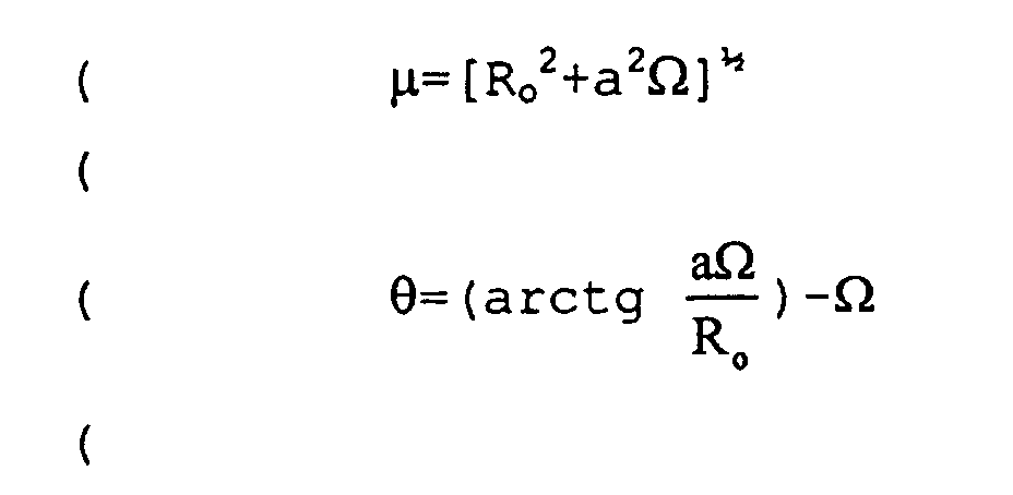
- Measurement device as described in one of claims 1 or 2, characterised by the fact that the distance (Ro) between the axis (δR) of rotation of the encoder (4) and the axis (δc) of the sensor (5) is zero.
- Measurement device as described in one of claims 1, 2, or 3, characterised by the fact that the angle of phase-shift (Γ) between the two signals from the two sensitive elements (51) and (52) of the sensor (5) has a value equal to an odd number of times π/2, locating the sensitive elements of the sensor in a quadrature situation in the magnetic field of the encoder.
- Measurement device as described in one of claims 1, 2, or 3, characterised by the fact that the angle (Γ) of phase-shift between the two signals from the sensitive elements (51) and (52) of the sensor (5) has a value less than π/2 corresponding to a low value of the distance (d) between the sensitive elements, and by the fact that the sensor carries a single means for electronic orthogonalisation of the signals from the said sensitive elements.
- Measurement device as described in one of claims 1, 2, or 3, characterised by the fact that the internal diameter (Φi) of the annular encoder (4) is greater than twice the inter-axial distance (Ro).
- Measurement device as described in claims 1 to 6, characterised by the fact that the magnetic transitions carried by the annular encoder are arcs of circles (14), the radii and the positions of the centres of which correspond to the radius of curvature (r) and to the positions of the centres of curvature (O') of the points on the spirals (15) situated at the mean diameter (Φm) of the annular magnetic encoder (4).
- Measurement device as described in claims 1 to 6, characterised by the fact that the magnetic transitions carried by the annular encoder are arcs of circles (14), the lines of which are obtained by a method minimising the mean of the quadratic distances between the arc of circle line and the arc of spiral line (15) for each of the transitions.
- Measurement device as described in claims 1 to 6, characterised by the fact that the magnetic transitions carried by annular encoders are linear (17), the lines of which correspond to the tangents (18) to the points on the spirals situated at the mean diameter (Φm) of the annular magnetic encoder.
- Measurement device as described in claims 1 to 6, characterised by the fact that the magnetic transitions carried by the annular encoders are linear (17), the lines of which are obtained by a method minimising the mean of the quadratic distances between the arc of spiral line (19) and the straight line for each of the transitions.
- Measurement device as described in claims 1 to 6, characterised by the fact that the magnetic transitions carried by the annular magnetic encoders are linear secant to the spirals, each linear transition passing through the two end points (P1 and P2) of each spiral transition of the surface of the annular encoder.
- Device for measurement of velocity or position as described in one of claims 1, 2, or 3, characterised by the fact that the axis of the sensor carrying the centre of the sensitive elements is maintained in a known position in the device, whatever the means of connection between the sensor and the fixed frame.
Applications Claiming Priority (2)
| Application Number | Priority Date | Filing Date | Title |
|---|---|---|---|
| FR9716783 | 1997-12-31 | ||
| FR9716783A FR2773212B1 (en) | 1997-12-31 | 1997-12-31 | POSITION AND SPEED SENSORS OF A ROTATING SHAFT |
Publications (2)
| Publication Number | Publication Date |
|---|---|
| EP0927872A1 EP0927872A1 (en) | 1999-07-07 |
| EP0927872B1 true EP0927872B1 (en) | 2003-07-02 |
Family
ID=9515366
Family Applications (1)
| Application Number | Title | Priority Date | Filing Date |
|---|---|---|---|
| EP98403147A Expired - Lifetime EP0927872B1 (en) | 1997-12-31 | 1998-12-14 | Speed and position sensors for rotating shafts |
Country Status (5)
| Country | Link |
|---|---|
| US (1) | US6163147A (en) |
| EP (1) | EP0927872B1 (en) |
| JP (1) | JPH11248486A (en) |
| DE (1) | DE69816020T2 (en) |
| FR (1) | FR2773212B1 (en) |
Families Citing this family (25)
| Publication number | Priority date | Publication date | Assignee | Title |
|---|---|---|---|---|
| DE19849613A1 (en) * | 1998-10-28 | 2000-05-04 | Philips Corp Intellectual Pty | Arrangement for measuring a relative linear position |
| EP1208348B1 (en) * | 2000-03-08 | 2012-07-18 | Mts Systems Corporation | Linear and rotary magnetic sensor |
| JP2003211765A (en) | 2001-11-16 | 2003-07-29 | Matsushita Electric Ind Co Ltd | Printing device and roll device |
| ITTO20030024A1 (en) * | 2003-01-20 | 2004-07-21 | Rft Spa | PHONE WHEEL CONTROL DEVICE |
| US7229746B2 (en) * | 2003-04-02 | 2007-06-12 | Delphi Technologies, Inc. | Printed high strength permanent magnet targets for magnetic sensors |
| DE102005021300B4 (en) * | 2005-05-09 | 2007-08-16 | Vs Sensorik Gmbh | encoders |
| FR2898189B1 (en) * | 2006-03-02 | 2008-10-17 | Moving Magnet Tech | POSITION SENSOR WITH VARIABLE MAGNET DIRECTION AND METHOD OF MAKING SAME |
| ITTO20060771A1 (en) * | 2006-10-25 | 2008-04-26 | Elmotron S R L | POSITION AND ANGULAR SPEED DETECTOR DEVICE OF A ROTATING ELEMENT |
| JP2009168679A (en) * | 2008-01-17 | 2009-07-30 | Denso Corp | Rotation detector |
| FR2935485B1 (en) * | 2008-08-28 | 2010-09-10 | Roulements Soc Nouvelle | SYSTEM AND METHOD FOR MEASURING THE AXIAL MOTION OF A ROTATING MOBILE WORKPIECE |
| DE102008043556B4 (en) | 2008-11-07 | 2022-03-31 | Dr. Johannes Heidenhain Gmbh | position measuring device |
| US10704925B2 (en) * | 2009-01-12 | 2020-07-07 | Infineon Technologies Ag | Sensor and method for determining angular position including measuring magnetic field lines at a distance greater than the inner radius and less than the outer radius of a ring magnet, and at a distance greater than the outer radius or less than the inner radius |
| DE102009023395B4 (en) | 2009-05-29 | 2019-06-19 | Lakeview Innovation Ltd. | Code disc for an encoder |
| WO2016029972A1 (en) * | 2014-08-29 | 2016-03-03 | Aktiebolaget Skf | Sensor-bearing unit, mechanical system comprising such unit and method for manufacturing such unit |
| DE202014105652U1 (en) * | 2014-11-24 | 2015-06-18 | Infineon Technologies Ag | Magnetic arrangement for magnetic position sensor and corresponding position sensor device |
| CN104571116B (en) * | 2015-01-09 | 2017-02-22 | 西安应用光学研究所 | Position loop coordinate system conversion method of photoelectricity stable platform |
| FR3051552B1 (en) * | 2016-05-18 | 2018-05-25 | Continental Automotive France | LINEAR INDUCTIVE POSITION SENSOR FOR AN ANGULAR MEASUREMENT OF A MECHANICAL PIECE IN ROTATION |
| FR3055959B1 (en) * | 2016-09-13 | 2018-10-12 | Ntn Snr Roulements | SYSTEM FOR DETERMINING AT LEAST ONE PARAMETER OF ROTATION OF A ROTATING ORGAN |
| FR3055960B1 (en) * | 2016-09-13 | 2018-10-12 | Ntn Snr Roulements | ENCODER AND SYSTEM FOR DETERMINING AT LEAST ONE ROTATIONAL PARAMETER COMPRISING SUCH A CODER |
| JP6798530B2 (en) * | 2018-02-28 | 2020-12-09 | 株式会社デンソー | Linear position sensor |
| FR3078775B1 (en) * | 2018-03-12 | 2020-04-03 | Ntn-Snr Roulements | SYSTEM FOR DETERMINING AT LEAST ONE ROTATION PARAMETER OF A ROTATING MEMBER |
| EP3671222A1 (en) | 2018-12-18 | 2020-06-24 | Baumer Electric AG | Rotary encoder device with two detectors on a shared unit holder |
| FR3093798B1 (en) * | 2019-03-12 | 2021-06-25 | Ntn Snr Roulements | System for determining at least one parameter of the rotation of a rotating member |
| CN112986608B (en) * | 2021-03-31 | 2023-04-11 | 长光卫星技术股份有限公司 | Micro-nano satellite reaction flywheel speed measurement method based on linear Hall |
| EP4675298A3 (en) * | 2024-07-02 | 2026-01-28 | Honeywell International Inc. | Off-axis magnetic field sensor |
Family Cites Families (3)
| Publication number | Priority date | Publication date | Assignee | Title |
|---|---|---|---|---|
| DE2423500C3 (en) * | 1974-05-15 | 1980-05-29 | Siemens Ag, 1000 Berlin Und 8000 Muenchen | Arrangement for generating electrical signals with field plates |
| US5017776A (en) * | 1989-03-10 | 1991-05-21 | Hewlett-Packard Company | Apparatus for and methods of optical encoding having spiral shaped light modulator |
| DE9420147U1 (en) * | 1994-12-16 | 1995-03-02 | Ind Tech Res Inst | Flat magnetic encoder for an absolute position of a rotating part |
-
1997
- 1997-12-31 FR FR9716783A patent/FR2773212B1/en not_active Expired - Fee Related
-
1998
- 1998-12-14 DE DE69816020T patent/DE69816020T2/en not_active Expired - Fee Related
- 1998-12-14 EP EP98403147A patent/EP0927872B1/en not_active Expired - Lifetime
- 1998-12-30 US US09/223,484 patent/US6163147A/en not_active Expired - Lifetime
-
1999
- 1999-01-04 JP JP11000177A patent/JPH11248486A/en not_active Withdrawn
Also Published As
| Publication number | Publication date |
|---|---|
| EP0927872A1 (en) | 1999-07-07 |
| US6163147A (en) | 2000-12-19 |
| FR2773212A1 (en) | 1999-07-02 |
| FR2773212B1 (en) | 2000-03-31 |
| DE69816020T2 (en) | 2004-06-03 |
| DE69816020D1 (en) | 2003-08-07 |
| JPH11248486A (en) | 1999-09-17 |
Similar Documents
| Publication | Publication Date | Title |
|---|---|---|
| EP0927872B1 (en) | Speed and position sensors for rotating shafts | |
| EP1949036B1 (en) | Magnetic angular position sensor for a course up to 360° | |
| EP1017967B1 (en) | Digital relative position sensor | |
| EP1989505B1 (en) | Position sensor with variable direction of magnetization and method of production | |
| EP2496914B1 (en) | Bidirectional magnetic position sensor having field rotation | |
| EP2452160B1 (en) | Multi-periodic absolute position sensor | |
| EP1403622B1 (en) | Absolute angle sensor | |
| FR3048079A1 (en) | ROTATION ANGLE SENSOR | |
| WO2008071875A2 (en) | Rotary or linear position sensor having avariable magnet profile | |
| EP0151159A1 (en) | Multiphase motor with magnetized motor having n/2 pairs of poles per face | |
| WO2010046550A1 (en) | Magnetic position sensor with field direction measurement and flux collector | |
| EP1102995B1 (en) | Bearing provided with an information sensor | |
| EP2499464B1 (en) | Angular position sensor and assembly comprising a rotary system and such a sensor | |
| CN102654385A (en) | Sensor arrangement | |
| EP0939293B1 (en) | Multipolar magnetic ring | |
| FR3051552A1 (en) | LINEAR INDUCTIVE POSITION SENSOR FOR AN ANGULAR MEASUREMENT OF A MECHANICAL PIECE IN ROTATION | |
| EP0319355A2 (en) | Bearing with a magnetic field detector | |
| WO2016169645A1 (en) | Sensor for measuring the torque of a drive shaft | |
| EP0443937B1 (en) | Speed sensor for transmission output | |
| EP1404016B1 (en) | Device for controlling an electronically-commutated motor comprising angularly distributed singularities | |
| FR2833663A1 (en) | BEARING COMPRISING A WIRELESS INFORMATION TRANSMISSION ASSEMBLY | |
| EP3708963A1 (en) | System for determining at least one rotation parameter of a rotating member | |
| EP4235109B1 (en) | Test body with encoder | |
| EP4235127B1 (en) | System for determining a torque | |
| FR3058202B1 (en) | TAP FOR FLUID TANK AND BOTTLE COMPRISING SUCH FAUCET |
Legal Events
| Date | Code | Title | Description |
|---|---|---|---|
| PUAI | Public reference made under article 153(3) epc to a published international application that has entered the european phase |
Free format text: ORIGINAL CODE: 0009012 |
|
| AK | Designated contracting states |
Kind code of ref document: A1 Designated state(s): DE ES FR IT |
|
| AX | Request for extension of the european patent |
Free format text: AL;LT;LV;MK;RO;SI |
|
| 17P | Request for examination filed |
Effective date: 19990913 |
|
| AKX | Designation fees paid |
Free format text: DE ES FR GB |
|
| RBV | Designated contracting states (corrected) |
Designated state(s): DE ES FR IT |
|
| GRAH | Despatch of communication of intention to grant a patent |
Free format text: ORIGINAL CODE: EPIDOS IGRA |
|
| GRAH | Despatch of communication of intention to grant a patent |
Free format text: ORIGINAL CODE: EPIDOS IGRA |
|
| GRAA | (expected) grant |
Free format text: ORIGINAL CODE: 0009210 |
|
| AK | Designated contracting states |
Designated state(s): DE ES FR IT |
|
| PG25 | Lapsed in a contracting state [announced via postgrant information from national office to epo] |
Ref country code: ES Free format text: LAPSE BECAUSE OF FAILURE TO SUBMIT A TRANSLATION OF THE DESCRIPTION OR TO PAY THE FEE WITHIN THE PRESCRIBED TIME-LIMIT Effective date: 20030702 |
|
| REF | Corresponds to: |
Ref document number: 69816020 Country of ref document: DE Date of ref document: 20030807 Kind code of ref document: P |
|
| PLBE | No opposition filed within time limit |
Free format text: ORIGINAL CODE: 0009261 |
|
| STAA | Information on the status of an ep patent application or granted ep patent |
Free format text: STATUS: NO OPPOSITION FILED WITHIN TIME LIMIT |
|
| 26N | No opposition filed |
Effective date: 20040405 |
|
| PGFP | Annual fee paid to national office [announced via postgrant information from national office to epo] |
Ref country code: IT Payment date: 20071221 Year of fee payment: 10 |
|
| PGFP | Annual fee paid to national office [announced via postgrant information from national office to epo] |
Ref country code: DE Payment date: 20071221 Year of fee payment: 10 |
|
| PGFP | Annual fee paid to national office [announced via postgrant information from national office to epo] |
Ref country code: FR Payment date: 20071217 Year of fee payment: 10 |
|
| REG | Reference to a national code |
Ref country code: FR Ref legal event code: ST Effective date: 20090831 |
|
| PG25 | Lapsed in a contracting state [announced via postgrant information from national office to epo] |
Ref country code: DE Free format text: LAPSE BECAUSE OF NON-PAYMENT OF DUE FEES Effective date: 20090701 |
|
| PG25 | Lapsed in a contracting state [announced via postgrant information from national office to epo] |
Ref country code: FR Free format text: LAPSE BECAUSE OF NON-PAYMENT OF DUE FEES Effective date: 20081231 |
|
| PG25 | Lapsed in a contracting state [announced via postgrant information from national office to epo] |
Ref country code: IT Free format text: LAPSE BECAUSE OF NON-PAYMENT OF DUE FEES Effective date: 20081214 |