EP0927861B1 - Cooling storage system with an ice bank - Google Patents
Cooling storage system with an ice bank Download PDFInfo
- Publication number
- EP0927861B1 EP0927861B1 EP97810811A EP97810811A EP0927861B1 EP 0927861 B1 EP0927861 B1 EP 0927861B1 EP 97810811 A EP97810811 A EP 97810811A EP 97810811 A EP97810811 A EP 97810811A EP 0927861 B1 EP0927861 B1 EP 0927861B1
- Authority
- EP
- European Patent Office
- Prior art keywords
- heat exchanger
- container
- water
- cold
- circuit
- Prior art date
- Legal status (The legal status is an assumption and is not a legal conclusion. Google has not performed a legal analysis and makes no representation as to the accuracy of the status listed.)
- Expired - Lifetime
Links
Images


Classifications
-
- F—MECHANICAL ENGINEERING; LIGHTING; HEATING; WEAPONS; BLASTING
- F28—HEAT EXCHANGE IN GENERAL
- F28D—HEAT-EXCHANGE APPARATUS, NOT PROVIDED FOR IN ANOTHER SUBCLASS, IN WHICH THE HEAT-EXCHANGE MEDIA DO NOT COME INTO DIRECT CONTACT
- F28D20/00—Heat storage plants or apparatus in general; Regenerative heat-exchange apparatus not covered by groups F28D17/00 or F28D19/00
- F28D20/02—Heat storage plants or apparatus in general; Regenerative heat-exchange apparatus not covered by groups F28D17/00 or F28D19/00 using latent heat
- F28D20/021—Heat storage plants or apparatus in general; Regenerative heat-exchange apparatus not covered by groups F28D17/00 or F28D19/00 using latent heat the latent heat storage material and the heat-exchanging means being enclosed in one container
-
- F—MECHANICAL ENGINEERING; LIGHTING; HEATING; WEAPONS; BLASTING
- F25—REFRIGERATION OR COOLING; COMBINED HEATING AND REFRIGERATION SYSTEMS; HEAT PUMP SYSTEMS; MANUFACTURE OR STORAGE OF ICE; LIQUEFACTION SOLIDIFICATION OF GASES
- F25D—REFRIGERATORS; COLD ROOMS; ICE-BOXES; COOLING OR FREEZING APPARATUS NOT OTHERWISE PROVIDED FOR
- F25D16/00—Devices using a combination of a cooling mode associated with refrigerating machinery with a cooling mode not associated with refrigerating machinery
-
- Y—GENERAL TAGGING OF NEW TECHNOLOGICAL DEVELOPMENTS; GENERAL TAGGING OF CROSS-SECTIONAL TECHNOLOGIES SPANNING OVER SEVERAL SECTIONS OF THE IPC; TECHNICAL SUBJECTS COVERED BY FORMER USPC CROSS-REFERENCE ART COLLECTIONS [XRACs] AND DIGESTS
- Y02—TECHNOLOGIES OR APPLICATIONS FOR MITIGATION OR ADAPTATION AGAINST CLIMATE CHANGE
- Y02E—REDUCTION OF GREENHOUSE GAS [GHG] EMISSIONS, RELATED TO ENERGY GENERATION, TRANSMISSION OR DISTRIBUTION
- Y02E60/00—Enabling technologies; Technologies with a potential or indirect contribution to GHG emissions mitigation
- Y02E60/14—Thermal energy storage
Definitions
- the present invention relates to a cold storage system with an ice store according to the preamble of claim 1.
- Such Plant is e.g. known from US-A-5 647 225.
- Such cold storage systems with an ice store are particularly used in air conditioning and refrigeration systems that need refrigeration, the enormous fluctuations, for example, within 24 hours is subject. For example, during the night a very small one There is a need for cooling, while during the day this requirement can be very high. Without the use of such memories, the performance would have to be corresponding Refrigeration systems can be designed for this peak load. That would be but the systems are oversized for most of the operating hours. This would result in unnecessarily high investment and operating costs Plant efficiency is very low.
- ice stores can, for example, generate cold be done during the night. This is particularly so then worthwhile if the electricity can be obtained at a lower tariff can.
- the storage unit can then use the cold the electrical load peaks are covered by chillers are massively reduced. Such systems can be dimensioned smaller be what a much better use of the system and features lower operating costs.
- Ice stores that consist of an insulated container that is filled with water is provided with heat exchangers with appropriate heat exchanger tubes.
- a medium is used to charge the storage tank through the heat exchanger tubes passed, which is cooled in a refrigerator.
- Arise in the container then growing ice cylinders arranged around the respective heat exchanger tubes.
- water is poured into the container from above fed, while the cooled water is discharged in the bottom of the container can.
- those formed around the heat exchanger tubes are formed Water flows around ice cylinders, the ice cylinders melt.
- This type of ice water storage has the disadvantage that the Water in the tank is not fully charged when the storage tank is being charged allowed to freeze to an ice block, as flow-through spaces for the water must be present in order for an efficient between ice cylinder and water Heat transfer can take place.
- the individual heat exchanger tubes have enough distance from each other, which is a big one Requires space.
- ice stores which also have water Have filled insulated container in the same way in the heat exchanger are used with heat exchanger tubes, and through which one in one Chiller circulates cooled medium, so that is in the container Water is converted into ice when the storage tank is charged. Here can be cooled until the water is completely frozen and forms an ice block. Unloading takes place with these ice stores like with the Charging through the heat exchanger tubes of the heat exchanger by the Heat exchanger tubes the medium to be cooled is passed through, which then can be supplied cooled to a corresponding system. Through the heat transfer the ice is melted, first in the immediate vicinity the heat exchanger tubes.
- These ice stores have the advantage that the design is very compact because the heat exchanger tubes are relatively close can be arranged together.
- the operational security is very high, it it is not necessary that the discharge be carried out until the ice completely melted into water, recharging can be done at any time be performed.
- the efficiency of this ice storage is compared to the previous one shown ice stores lower, since soon after the unloading process between the heat exchanger tubes and the surrounding ice space filled with water is created, which increases the efficiency of heat transfer is restricted.
- the object of the invention is to provide a cold storage system to be designed with an ice store so that high efficiency is achieved is that the ice store can be charged at any time without having to do so a complete discharge must have taken place for the Provided cooled medium has a low temperature and that no surveillance personnel is required.
- the water removed when the ice storage is unloaded can for example, additionally cool the working medium via a heat exchanger, and then returned to the container, but it is also conceivable that the water removed from the tank goes directly to the working medium is added, which also achieves additional cooling. Fresh water can also be supplied to the tank in this application.
- the return line is advantageously in the working medium circuit and the flow line directly connected to each other via another line, being at the junction of the further line with the flow line a bypass valve is arranged, which allows the temperature the working medium that is released by the corresponding system, can be regulated.
- Another advantageous embodiment of the invention consists in that the water is supplied over the entire surface in the container, and that the withdrawal of water over the entire floor area of the Distributed container is carried out. This will ensure even unloading of ice storage reached.
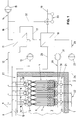
- the cold storage system comprises one Ice store 1, which consists of an insulated container 2.
- This container 2 is filled with water 3.
- First heat exchangers 4 are inserted in container 2, each consisting of two tubes 5 arranged in parallel, which are connected via heat exchanger tubes 6, which form a loop 7, are connected to one another, as will be described later.
- first heat exchangers 4 do not form together with one shown refrigerator a first circuit 8.
- a medium which is preferably a glycol solution is. This medium comes from the refrigerator, not shown when charging the ice store via the feed lines 9 into the first Heat exchanger 4 and via the removal lines 10 again to the not shown Chiller.
- the water 3 in the container 2 freezes during this charging process to ice, as will be described later.
- the refrigerator To unload the ice store, the refrigerator, not shown, which together with the first heat exchangers 4 the first cycle 8 form, switched off in a known manner. Form the first heat exchanger 4 now together with a second heat exchanger 11 a second circuit 12, in which the medium can circulate, driven by the second Pump 13.
- This second heat exchanger 11 is from a working medium run through, which circulates in a working medium circuit 14, driven by a first pump 15.
- This working medium does not come from a Cooling system shown via a return line 16 in the second heat exchanger 11.
- the working medium enters via a connecting line 17 a third heat exchanger 18, passes through it, and is via a flow line 19 fed to the cooling system, not shown.
- the third heat exchanger 18 is in a third circuit 20 from Water 3 flows through the container 2.
- the pipelines 23 are provided with through openings through which the withdrawing water can flow into the pipes 23. That water is via line 24 by means of a third pump 25 in the third heat exchanger 18 passed, flows through it and is via the line 26 Feed means 27 supplied.
- These feed means 27 also consist of several pipes 28, which is distributed in the region of the surface of the water 3 in the container 2 arranged and connected to each other. These pipes 28 are also equipped with through openings through which the flowing back Water can flow into the container 2.
- ⁇ means 29 for circulation of water 3 is provided in container 2.
- These means 29 consist of a Compressed air line network, the lines 30 in the bottom region 21 of the container 2 are arranged. These lines 30 are connected via a compressed air compressor 31 Compressed air supplied, these lines 30 are equipped with holes through which flows the compressed air supplied into the water 3. The bubbles rise in the water 3 of the container 2, whereby practically the entire water volume is constantly moving.
- That from the first heat exchangers 4 into the second heat exchanger 11 conducted medium has, for example, a temperature of about 3 ° C. on.
- the working medium conducted into the second heat exchanger 11 has one Temperature of about 9 ° C. This is in this second heat exchanger 11 Working medium cooled to about 5 ° C. That from the second heat exchanger 11 derived medium, which is returned to the first heat exchanger 4 is heated to about 7 ° C.
- That passed via line 24 into the third heat exchanger 18 Water, for example, has a temperature of around 0.3 ° C.
- the third heat exchanger 18 becomes the working medium supplied via line 17, the has a temperature of about 5 ° C, cooled to, for example, 1 ° C cooled working medium is then on the flow line 19 of the cooling system fed.
- the water returned via line 26 into the container has a temperature of about 3 ° after leaving the third heat exchanger C on.
- a further line 32 is provided, which the Return line 16 and the flow line 19 connects directly to each other.
- a bypass valve 33 is attached.
- This bypass valve 33 can be known Ways can be controlled, reducing the flow temperature of the working medium can be regulated.
- Fig. 2 shows the circuit diagram of a second embodiment of a Cold storage system according to the invention with ice storage.
- the ice store exists in an identical manner to the first embodiment 1 from an insulated container 2, which is filled with water 3.
- the first heat exchangers 4 are provided, formed by the tubes 5 and the heat exchanger tubes 6, which form loops 7. Charging the ice store takes place in the same way as described for FIG. 1, via the first circuit 8, the water 3, which is located in the container 2, too Ice freezes.
- the refrigerator and the first circuit switched off.
- the medium by means of the second pump 13, which also consists of a glycol solution through the second heat exchanger 11 passed and gets back into the first heat exchanger 4.
- the working medium which in a Working medium circuit 14 circulates, driven by the first pump 15.
- the working medium is water.
- the Water After passing through the second heat exchanger 11, the Water is supplied to the feed means 27 via a first connecting line 34, the water thus gets into the container 2.
- the removal means 22 are over a second connecting line 35 with the flow line 19 of the working medium circuit 14 connected.
- the water flowing through the return line 16 to the second heat exchanger 11 has a temperature of, for example, about 9 ° C on.
- this second heat exchanger 11 it is cooled to, for example about 5 ° C.
- the medium introduced into the second heat exchanger 11, which consists of the first heat exchanger 4 comes, has a temperature of about 3 ° C, will heated in the second heat exchanger 11 to, for example, 7 ° C. and in the first Heat exchanger 4 returned.
- the on the way 22 from the Water removed from the container has a temperature of approximately, for example 0.3 ° C, and thus reaches the feed line 19.
- the return line 16 is also in this exemplary embodiment and the flow line 19 directly connected to one another by a further line 32, in the connection point between this further line 32 and the flow line 19 a bypass valve 33 is also used, whereby the flow temperature can be regulated in a known manner.
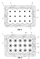
- FIG. 3 shows the structure of an ice store 1. This exists from the container 2, which is composed of insulated walls 36 is.
- the first heat exchangers 4 are inserted, which are made of the tubes 5 arranged in parallel are assembled, which over the Heat exchanger tubes 6, which form loops 7, connected to one another are.
- One of the pipes 5 is connected to the removal line 10.
- the other tube 5 of the first heat exchanger 4 is in a manner not shown with the feed line 9 (Fig. 1) connected.
- the feed means 27, which, as has already been described for FIG. 1, from Pipes 28 exist in which holes are made through which the water can flow into the container 2.
- the removal means 22 are shown in the bottom region 21 of the container, which also, as already described, have pipes 23 which are provided with holes through which the water of the container 2 in these pipes 23 can pass through line 24 for further use is derived.
- the means for circulating the water in the container 2 attached which are formed from compressed air lines 30 which are provided with bores, through which the supplied compressed air escape into the water 3 of the container 2 can.
- first heat exchanger 4 and 5 show the structure of the first heat exchanger 4.
- Each such a first heat exchanger 4 is made of two parallel to each other extending tubes 5 formed.
- a channel 37 is located along each of these tubes 5 attached, which is connected to the respective tube 5 via holes 38.
- One end 39 of a heat exchanger tube 6 is in the channel 37 of one Tube 5 used.
- the other end 40 of this heat exchanger tube 6 connected to the other channel 37 of the other tube 5. This forms the corresponding heat exchanger tube 6 has a loop 7.
- the tubes 5, the channels 37 and Heat exchanger tubes 6 of these first heat exchangers 4 made of polypropylene.
- Fig. 6 shows the representation of a Cutting plane through the container 2 of the ice store 1, which is normal to the vertically extending heat exchanger tubes 6 is placed.
- Fig. 6 shows the State of fully discharged ice store. The water 3 is complete ice-free.
- This charging process is continued until the one shown in FIG shown ice cylinder 41 grow together and a complete block of ice 42 form, as shown in Fig. 8.
- This ice block 42 fills the Container not completely out, this ice block 42 is water 3 on all sides surround.
- This discharge process can last as long be continued until the ice has completely melted, creating the initial situation, shown in Fig. 6 is reached. But it is not necessary that the discharge takes place until the ice melts completely can also be in an intermediate stage, as shown, for example, in FIG. 9 is to start charging the ice storage again without that damage occurs. This is because the formation of the Ice starts around the heat exchanger tubes 6, the volume changes can by draining the water in the gaps between the new formed ice and the block of ice.
Abstract
Description
Die vorliegende Erfindung bezieht sich auf eine Kältespeicheranlage mit einem Eisspeicher gemäss dem Oberbegriff des Patentanspruchs 1. Eine solche Anlage ist z.B. aus der US-A-5 647 225 bekannt.The present invention relates to a cold storage system with an ice store according to the preamble of claim 1. Such Plant is e.g. known from US-A-5 647 225.
Derartige Kältespeicheranlagen mit einem Eisspeicher werden insbesondere bei Klima- und Kälteanlagen eingesetzt, die einen Kältebedarf haben, der beispielsweise innerhalb von 24 Stunden enormen Schwankungen unterworfen ist. Während der Nacht kann beispielsweise ein sehr geringer Kältebedarf vorliegen, während tagsüber dieser Bedarf sehr hoch sein kann. Ohne den Einsatz von derartigen Speichern müsste die Leistung von entsprechenden Kälteanlagen auf diese Spitzenlast ausgelegt werden. Dadurch wären aber die Anlagen für den grössten Teil der Betriebsstunden überdimensioniert. Hierdurch würden unnötig hohe Investitions- und Betriebskosten entstehen, der Anlagenutzungsgrad ist sehr niedrig.Such cold storage systems with an ice store are particularly used in air conditioning and refrigeration systems that need refrigeration, the enormous fluctuations, for example, within 24 hours is subject. For example, during the night a very small one There is a need for cooling, while during the day this requirement can be very high. Without the use of such memories, the performance would have to be corresponding Refrigeration systems can be designed for this peak load. That would be but the systems are oversized for most of the operating hours. This would result in unnecessarily high investment and operating costs Plant efficiency is very low.
Durch den Einsatz von Eisspeichern kann die Kälteerzeugung beispielsweise während der Nacht durchgeführt werden. Dies ist insbesondere dann lohnenswert, wenn der Strom zu einem niedrigeren Tarif bezogen werden kann. Tagsüber kann dann beispielsweise der Kältebedarf durch den Speicher abgedeckt werden, die elektrischen Belastungsspitzen durch Kältemaschinen werden massiv vermindert. Dadurch können derartige Anlagen kleiner dimensioniert werden, was sich durch eine wesentlich bessere Anlagenausnutzung und niedrigere Betriebskosten auszeichnet.The use of ice stores can, for example, generate cold be done during the night. This is particularly so then worthwhile if the electricity can be obtained at a lower tariff can. During the day, for example, the storage unit can then use the cold the electrical load peaks are covered by chillers are massively reduced. Such systems can be dimensioned smaller be what a much better use of the system and features lower operating costs.
Kältespeicheranlagen mit Eisspeicher sind bekannt. Hierbei sind die Eisspeicher, die aus einem isolierten Behälter bestehen, der mit Wasser gefüllt ist, mit Wärmetauschern mit entsprechenden Wärmetauscherrohren versehen. Zum Aufladen des Speichers wird durch die Wärmetauscherrohre ein Medium geleitet, das in einer Kältemaschine abgekühlt wird. Im Behälter entstehen dann wachsende, um die jeweiligen Wärmetauscherrohre angeordnete Eiszylinder. Zum Entladen dieses Speichers wird von oben in den Behälter Wasser zugeführt, während unten im Behälter das gekühlte Wasser abgeführt werden kann. Während dieses Vorgangs werden die um die Wärmetauscherrohre gebildeten Eiszylinder vom Wasser umströmt, die Eiszylinder schmelzen. Cold storage systems with ice storage are known. Here are the Ice stores that consist of an insulated container that is filled with water is provided with heat exchangers with appropriate heat exchanger tubes. A medium is used to charge the storage tank through the heat exchanger tubes passed, which is cooled in a refrigerator. Arise in the container then growing ice cylinders arranged around the respective heat exchanger tubes. To discharge this storage, water is poured into the container from above fed, while the cooled water is discharged in the bottom of the container can. During this process, those formed around the heat exchanger tubes are formed Water flows around ice cylinders, the ice cylinders melt.
Diese Art von Eiswasserspeicher weist den Nachteil auf, dass das sich im Behälter befindende Wasser beim Aufladen des Speichers nicht vollständig zu einem Eisblock gefrieren darf, da Durchströmräume für das Wasser vorhanden sein müssen, damit zwischen Eiszylinder und Wasser ein effizienter Wärmeübergang stattfinden kann. Demzufolge müssen die einzelnen Wärmetauscherrohre genügend Abstand voneinander haben, was einen grossen Platzbedarf zur Folge hat. Des weiteren ist es erforderlich, dass eine Entladung jeweils bis zur vollständigen Abschmelzung des Eises durchgeführt wird, bevor wieder mit der Aufladung, d.h. mit der Bildung von Eis, gestartet werden kann. Wenn kein vollständiges Abschmelzen stattfindet, besteht die Gefahr, dass sich durch ungleichmässiges Abschmelzen und ungleichmässiger Eisbildung im Behälter grosse Eisblöcke bilden können, die zum Entladen nicht mehr durch das Wasser durchströmt werden, wodurch eine Einbusse der Effizienz auftritt. Es ist somit erforderlich, dass derartige Eisspeicher überwacht werden, was zusätzliches Personal erfordert. Diese Eisspeicher sind somit eher für Industriebetriebe geeignet. Mit diesem Eisspeicher wird aber der Vorteil erreicht, dass das bei der Entladung abgeführte Wasser eine tiefe Temperatur aufweist, und dass die Entladeleistung gross ist.This type of ice water storage has the disadvantage that the Water in the tank is not fully charged when the storage tank is being charged allowed to freeze to an ice block, as flow-through spaces for the water must be present in order for an efficient between ice cylinder and water Heat transfer can take place. As a result, the individual heat exchanger tubes have enough distance from each other, which is a big one Requires space. Furthermore, it is necessary that a discharge each time until the ice has completely melted before again with charging, i.e. with the formation of ice. If there is no complete melting, there is a risk that through uneven melting and uneven ice formation Large ice blocks can form in the container, which are no longer used for unloading flowed through the water, reducing efficiency occurs. It is therefore necessary that such ice stores are monitored which requires additional staff. These ice stores are therefore more for industrial companies suitable. With this ice storage, however, the advantage is achieved that the water discharged during the discharge is at a low temperature, and that the discharge power is great.
Es sind auch Eisspeicher bekannt, die ebenfalls einen mit Wasser gefüllten isolierten Behälter aufweisen, in dem in gleicher Weise Wärmetauscher mit Wärmetauscherrohren eingesetzt sind, und durch welche ein in einer Kältemaschine gekühltes Medium zirkuliert, so dass das im Behälter sich befindende Wasser beim Aufladen des Speichers in Eis umgewandelt wird. Hierbei kann so lange gekühlt werden, bis das Wasser vollständig gefroren ist und einen Eisblock bildet. Die Entladung erfolgt bei diesen Eisspeichern wie bei der Aufladung über die Wärmetauscherrohre der Wärmetauscher, indem durch die Wärmetauscherrohre das zu kühlende Medium durchgeleitet wird, das dann gekühlt einer entsprechenden Anlage zugeführt werden kann. Durch den Wärmeübergang wird das Eis geschmolzen, wobei dies zuerst in unmittelbarer Umgebung der Wärmetauscherrohre erfolgt. Diese Eisspeicher haben den Vorteil, dass die Bauweise sehr kompakt ist, da die Wärmetauscherrohre relativ nahe beieinander angeordnet sein können. Die Betriebssicherheit ist sehr gross, es ist nicht erforderlich, dass die Entladung solange durchgeführt wird, bis das Eis vollständig zu Wasser geschmolzen ist, ein Aufladen kann jederzeit wieder durchgeführt werden. Die Effizienz dieser Eisspeicher ist gegenüber den vorgängig dargestellten Eisspeichern geringer, da schon bald nach dem Entladevorgang zwischen den Wärmetauscherrohren und dem umgebenden Eis ein mit Wasser gefüllter Raum entsteht, wodurch die Effizienz des Wärmeübergangs eingeschränkt wird.There are also ice stores known, which also have water Have filled insulated container in the same way in the heat exchanger are used with heat exchanger tubes, and through which one in one Chiller circulates cooled medium, so that is in the container Water is converted into ice when the storage tank is charged. Here can be cooled until the water is completely frozen and forms an ice block. Unloading takes place with these ice stores like with the Charging through the heat exchanger tubes of the heat exchanger by the Heat exchanger tubes the medium to be cooled is passed through, which then can be supplied cooled to a corresponding system. Through the heat transfer the ice is melted, first in the immediate vicinity the heat exchanger tubes. These ice stores have the advantage that the design is very compact because the heat exchanger tubes are relatively close can be arranged together. The operational security is very high, it it is not necessary that the discharge be carried out until the ice completely melted into water, recharging can be done at any time be performed. The efficiency of this ice storage is compared to the previous one shown ice stores lower, since soon after the unloading process between the heat exchanger tubes and the surrounding ice space filled with water is created, which increases the efficiency of heat transfer is restricted.
Die Aufgabe der Erfindung besteht nun darin, eine Kältespeicheranlage mit einem Eisspeicher so zu gestalten, dass eine hohe Effizienz erreicht wird, dass der Eisspeicher jederzeit aufgeladen werden kann, ohne dass vorgängig eine vollständige Entladung stattgefunden haben muss, dass das zur Verfügung gestellte gekühlte Medium eine tiefe Temperatur aufweist und dass kein Überwachungspersonal erforderlich ist.The object of the invention is to provide a cold storage system to be designed with an ice store so that high efficiency is achieved is that the ice store can be charged at any time without having to do so a complete discharge must have taken place for the Provided cooled medium has a low temperature and that no surveillance personnel is required.
Erfindungsgemäss erfolgt die Lösung dieser Aufgabe durch die im Anspruch 1 aufgeführte Merkmalskombination.According to the invention this object is achieved by the Claim 1 listed combination of features.
Durch diese Anordnung kommen die jeweiligen Vorteile, die die beiden vorgängig dargestellten Eisspeicher auszeichnen, gemeinsam zum Tragen. Bei der Entladung des Speichers entstehen zwischen den Wärmetauscherrohren der ersten Wärmetauscher im Behälter und dem diese umgebenden Eis durch das Abschmelzen des Eises sehr rasch Durchgänge, durch welche das Wasser zirkulieren kann. Das die Wärmetauscherrohre der ersten Wärmetauscher durchströmende Medium wird über einen zweiten Kreislauf in einen zweiten Wärmetauscher geleitet, in welchem das Arbeitsmedium des Arbeitsmediumkreislaufes gekühlt wird. Gleichzeitig wird das Wasser dem Behälter entnommen, mit welchem das Arbeitsmedium zusätzlich gekühlt werden kann. Dadurch wird ein optimaler Wirkungsgrad erreicht.This arrangement gives the respective advantages that the two Mark the ice store previously shown, to wear together. When the storage tank is discharged, it is created between the heat exchanger tubes the first heat exchanger in the tank and the one surrounding it Ice by melting the ice very quickly passes through which the water can circulate. This is the first heat exchanger tube Medium flowing through heat exchanger is in via a second circuit passed a second heat exchanger in which the working medium of Working medium circuit is cooled. At the same time, the water becomes the container removed, with which the working medium are additionally cooled can. This ensures optimal efficiency.
5 Das beim Entladen des Eisspeichers entnommene Wasser kann beispielsweise über einen Wärmetauscher das Arbeitsmedium zusätzlich kühlen, und danach in den Behälter zurückgeleitet werden, es ist aber auch denkbar, dass das dem Behälter entnommene Wasser direkt dem Arbeitsmedium beigemischt wird, wodurch ebenfalls eine zusätzliche Kühlung erreicht wird. Dem Behälter kann bei dieser Anwendung auch Frischwasser zugeführt werden. 5 The water removed when the ice storage is unloaded can for example, additionally cool the working medium via a heat exchanger, and then returned to the container, but it is also conceivable that the water removed from the tank goes directly to the working medium is added, which also achieves additional cooling. Fresh water can also be supplied to the tank in this application.
In vorteilhafter Weise sind im Arbeitsmediumkreislauf die Rücklaufleitung und die Vorlaufleitung über eine weitere Leitung direkt miteinander verbunden, wobei bei der Verbindungsstelle der weiteren Leitung mit der Vorlaufleitung ein Bypassventil angeordnet ist, was ermöglicht, dass die Temperatur des Arbeitsmediums, das von der entsprechenden Anlage abgegeben wird, geregelt werden kann.The return line is advantageously in the working medium circuit and the flow line directly connected to each other via another line, being at the junction of the further line with the flow line a bypass valve is arranged, which allows the temperature the working medium that is released by the corresponding system, can be regulated.
Um einen guten Wirkungsgrad zu erreichen, ist es erforderlich, dass das Wasser im Behälter ständig in Bewegung gehalten wird, wozu Mittel zur Umwälzung vorgesehen sind. In vorteilhafter Weise bestehen diese Mittel aus einem Druckluftleitungsnetz, dessen Leitungen im Bodenbereich des Behälters angeordnet sind, und in welche Druckluft einspeisbar ist, die dann durch in den Leitungen angebrachte Bohrungen in den Behälter ausströmt und in Form von Blasen an die Oberfläche des Wassers aufsteigt. Dadurch wird in einfacher Weise eine optimale Bewegung des Wassers im Behälter erreicht, Toträume können keine entstehen.To achieve good efficiency, it is necessary that the water in the container is kept in motion, which means for Circulation are provided. These means advantageously consist of a compressed air line network, the lines in the bottom area of the container are arranged, and into which compressed air can be fed, which then by in the Pipes made in the tank flows out and in the form of Bubbles rise to the surface of the water. This will make it easier Optimal movement of the water in the tank achieved, dead spaces can not arise.
Eine weitere vorteilhafte Ausgestaltung der Erfindung besteht darin, dass die Zuführung des Wassers über die ganze Oberfläche im Behälter erfolgt, und dass die Entnahme des Wassers über die ganze Bodenfläche des Behälters verteilt durchgeführt wird. Damit wird ein gleichmässiges Entladen des Eisspeichers erreicht.Another advantageous embodiment of the invention consists in that the water is supplied over the entire surface in the container, and that the withdrawal of water over the entire floor area of the Distributed container is carried out. This will ensure even unloading of ice storage reached.
Weitere vorteilhafte Ausgestaltungen der erfindungsgemässen Anlage ergeben sich aus den weiteren abhängigen Ansprüchen.Further advantageous configurations of the system according to the invention result from the further dependent claims.
Ausführungsbeispiele der erfindungsgemässen Kältespeicheranlage werden nachfolgend anhand der beiliegenden Zeichnung beispielhaft näher erläutert.Embodiments of the cold storage system according to the invention are exemplified below with reference to the accompanying drawings explained.
Es zeigt:
Wie aus Fig. 1 ersichtlich ist, umfasst die Kältespeicheranlage einen
Eisspeicher 1, der aus einem isolierten Behälter 2 besteht. Dieser Behälter 2
ist mit Wasser 3 gefüllt. Im Behälter 2 sind erste Wärmetauscher 4 eingesetzt,
die jeweils aus zwei parallel angeordneten Rohren 5 bestehen, die über Wärmetauscherrohre
6, die eine Schlaufe 7 bilden, miteinander verbunden sind,
wie später noch beschrieben wird.As can be seen from Fig. 1, the cold storage system comprises one
Ice store 1, which consists of an
Diese ersten Wärmetauscher 4 bilden zusammen mit einer nicht
dargestellten Kältemaschine einen ersten Kreislauf 8. In diesem ersten Kreislauf
8 zirkuliert in bekannter Weise ein Medium, das vorzugsweise eine Glykollösung
ist. Dieses Medium gelangt aus der nicht dargestellten Kältemaschine
beim Aufladen des Eisspeichers über die Zuführleitungen 9 in die ersten
Wärmetauscher 4 und über die Wegführleitungen 10 wieder zur nicht dargestellten
Kältemaschine. Das Wasser 3 im Behälter 2 gefriert bei diesem Aufladevorgang
zu Eis, wie später noch beschrieben wird.These
Zum Entladen des Eisspeichers wird die nicht dargestellte Kältemaschine,
die zusammen mit den ersten Wärmetauschern 4 den ersten Kreislauf
8 bilden, in bekannter Weise abgeschaltet. Die ersten Wärmetauscher 4 bilden
nun zusammen mit einem zweiten Wärmetauscher 11 einen zweiten Kreislauf
12, in welchem das Medium zirkulieren kann, angetrieben durch die zweite
Pumpe 13.To unload the ice store, the refrigerator, not shown,
which together with the
Dieser zweite Wärmetauscher 11 wird von einem Arbeitsmedium
durchlaufen, welches in einem Arbeitsmediumkreislauf 14 zirkuliert, angetrieben
durch eine erste Pumpe 15. Dieses Arbeitsmedium gelangt aus einer nicht
dargestellten Kühlanlage über eine Rücklaufleitung 16 in den zweiten Wärmetauscher
11. Über eine Verbindungsleitung 17 gelangt das Arbeitsmedium in
einen dritten Wärmetauscher 18, durchläuft diesen, und wird über eine Vorlaufleitung
19 der nicht dargestellten Kühlanlage zugeleitet.This
Der dritte Wärmetauscher 18 wird in einem dritten Kreislauf 20 vom
Wasser 3 des Behälters 2 durchströmt. Hierzu sind im Bodenbereich 21 des
Behälters 2 Wegführmittel 22 angeordnet, die aus mehreren Rohrleitungen 23
bestehen, die verteilt angeordnet und miteinander verbunden sind. Die Rohrleitungen
23 sind mit Durchgangsöffnungen versehen, durch welche das zu
entnehmende Wasser in die Rohrleitungen 23 einströmen kann. Dieses Wasser
wird über die Leitung 24 mittels einer dritten Pumpe 25 in den dritten Wärmetauscher
18 geleitet, durchströmt diesen und wird über die Leitung 26 den
Zuführmitteln 27 zugeführt.The
Diese Zuführmittel 27 bestehen ebenfalls aus mehreren Rohrleitungen
28, die im Bereich der Oberfläche des Wassers 3 im Behälter 2 verteilt
angeordnet und miteinander verbunden sind. Diese Rohrleitungen 28 sind
ebenfalls mit Durchgangsöffnungen ausgestattet, durch welche das zurückfliessende
Wasser in den Behälter 2 ausströmen kann. These feed means 27 also consist of
Im Bodenbereich 21 des Behälters 2 sind Mittel 29 zur Umwälzung
des Wassers 3 im Behälter 2 vorgesehen. Diese Mittel 29 bestehen aus einem
Druckluftleitungsnetz, deren Leitungen 30 im Bodenbereich 21 des Behälters 2
angeordnet sind. Über einen Druckluftkompressor 31 wird diesen Leitungen 30
Druckluft zugeführt, diese Leitungen 30 sind mit Bohrungen ausgestattet, durch
welche die zugeführte Druckluft in das Wasser 3 ausströmt. Die Blasen steigen
im Wasser 3 des Behälters 2 auf, wodurch praktisch das ganze Wasservolumen
ständig bewegt wird.In the
Das aus den ersten Wärmetauschern 4 in den zweiten Wärmetauscher
11 geleitete Medium weist beispielsweise eine Temperatur von etwa 3° C
auf. Das in den zweiten Wärmetauscher 11 geleitete Arbeitsmedium weist eine
Temperatur von etwa 9° C auf. In diesem zweiten Wärmetauscher 11 wird dieses
Arbeitsmedium auf etwa 5° C abgekühlt. Das aus dem zweiten Wärmetauscher
11 abgeleitete Medium, das in die ersten Wärmetauscher 4 zurückgeleitet
wird, wird hierbei auf etwa 7° C erwärmt.That from the
Das über die Leitung 24 in den dritten Wärmetauscher 18 geleitete
Wasser hat beispielsweise eine Temperatur von etwa 0,3° C. Im dritten Wärmetauscher
18 wird das über die Leitung 17 zugeführte Arbeitsmedium, das
eine Temperatur von etwa 5° C hat, abgekühlt auf beispielsweise 1° C. Dieses
abgekühlte Arbeitsmedium wird dann über die Vorlaufleitung 19 der Kühlanlage
zugeführt. Das über die Leitung 26 in den Behälter rückgeführte Wasser weist
nach dem Verlassen des dritten Wärmetauschers eine Temperatur von etwa 3°
C auf.That passed via
Zwischen der Rücklaufleitung 16 des Arbeitsmediumkreislaufes 14
und der Vorlaufleitung 19 ist eine weitere Leitung 32 vorgesehen, welche die
Rücklaufleitung 16 und die Vorlaufleitung 19 direkt miteinander verbindet. In
der Verbindungsstelle dieser weiteren Leitung 32 mit der Vorlaufleitung 19 ist
ein Bypassventil 33 angebracht. Dieses Bypassventil 33 kann in bekannter
Weise angesteuert werden, wodurch die Vorlauftemperatur des Arbeitsmediums
geregelt werden kann. Between the
Fig. 2 zeigt das Schaltschema einer zweiten Ausführungsform einer
erfindungsgemässen Kältespeicheranlage mit Eisspeicher. Bei der Beschreibung
dieses zweiten Ausführungsbeispiels sind für identische Bauteile die gleichen
Bezugszeichen verwendet worden wie bei der Beschreibung von Fig. 1.
In identischer Weise wie beim ersten Ausführungsbeispiel besteht der Eisspeicher
1 aus einem isolierten Behälter 2, der mit Wasser 3 gefüllt ist. Ebenfalls
vorgesehen sind die ersten Wärmetauscher 4, gebildet durch die Rohre 5 und
die Wärmetauscherrohre 6, die Schlaufen 7 bilden. Das Aufladen des Eisspeichers
erfolgt in gleicher Weise, wie er zu Fig. 1 beschrieben worden ist, über
den ersten Kreislauf 8, wobei das Wasser 3, das sich im Behälter 2 befindet, zu
Eis gefriert.Fig. 2 shows the circuit diagram of a second embodiment of a
Cold storage system according to the invention with ice storage. In the description
of this second embodiment are the same for identical components
Reference numerals have been used as in the description of FIG. 1.
The ice store exists in an identical manner to the first embodiment
1 from an
Zum Entladen des Eisspeichers 1 wird, wie beim Ausführungsbeispiel
gemäss Fig. 1, die Kältemaschine und der erste Kreislauf ausgeschaltet.
Über den zweiten Kreislauf 12 wird mittels der zweiten Pumpe 13 das Medium,
das auch hier aus einer Glykollösung besteht, durch den zweiten Wärmetauscher
11 geleitet und gelangt in die ersten Wärmetauscher 4 zurück. Durch
diesen zweiten Wärmetauscher 11 wird in gleicher Weise wie beim vorgängig
beschriebenen Ausführungsbeispiel das Arbeitsmedium geleitet, das in einem
Arbeitsmediumkreislauf 14 zirkuliert, angetrieben durch die erste Pumpe 15. In
diesem Ausführungsbeispiel ist das Arbeitsmedium Wasser.To discharge the ice store 1, as in the exemplary embodiment
1, the refrigerator and the first circuit switched off.
Via the
Nach dem Durchlauf des zweiten Wärmetauschers 11 wird das
Wasser über eine erste Verbindungsleitung 34 den Zuführmitteln 27 zugeleitet,
das Wasser gelangt somit in den Behälter 2. Die Wegführmittel 22 sind über
eine zweite Verbindungsleitung 35 mit der Vorlaufleitung 19 des Arbeitsmediumkreislaufes
14 verbunden.After passing through the
Das Wasser, das über die Rücklaufleitung 16 dem zweiten Wärmetauscher
11 zugeleitet wird, weist eine Temperatur von beispielsweise etwa 9°
C auf. In diesem zweiten Wärmetauscher 11 wird es gekühlt auf beispielsweise
etwa 5° C. Das in den zweiten Wärmetauscher 11 eingeführte Medium, das aus
den ersten Wärmetauschern 4 kommt, hat eine Temperatur von etwa 3° C, wird
im zweiten Wärmetauscher 11 auf beispielsweise 7° C erwärmt und in die ersten
Wärmetauscher 4 zurückgeleitet. Das über die Wegführmittel 22 aus dem
Behälter entnommene Wasser weist beispielsweise eine Temperatur von etwa
0,3° C auf, und gelangt so in die Vorlaufleitung 19.The water flowing through the
Auch bei diesem Ausführungsbeispiel sind die Rücklaufleitung 16
und die Vorlaufleitung 19 durch eine weitere Leitung 32 direkt miteinander verbunden,
wobei in der Verbindungsstelle zwischen dieser weiteren Leitung 32
und der Vorlaufleitung 19 ebenfalls ein Bypassventil 33 eingesetzt ist, wodurch
in bekannter Weise die Vorlauftemperatur geregelt werden kann.The
In Fig. 3 ist der Aufbau eines Eisspeichers 1 ersichtlich. Dieser besteht
aus dem Behälter 2, der aus isolierten Wandungen 36 zusammengesetzt
ist. In diesem Behälter 2 sind die ersten Wärmetauscher 4 eingesetzt, die aus
den parallel angeordneten Rohren 5 zusammengesetzt sind, die über die
Wärmetauscherrohre 6, welche Schlaufen 7 bilden, miteinander verbunden
sind. Jeweils eines der Rohre 5 ist mit der Wegführleitung 10 verbunden. Das
andere Rohr 5 der ersten Wärmetauscher 4 ist in nicht dargestellter Weise mit
der Zuführleitung 9 (Fig. 1) verbunden. In dieser Darstellung sind die Zuführmittel
27 ersichtlich, die, wie bereits zu Fig. 1 beschrieben worden ist, aus
Rohrleitungen 28 bestehen, in welchen Bohrungen angebracht sind, durch
welche das Wasser in den Behälter 2 ausströmen kann.3 shows the structure of an ice store 1. This exists
from the
Im Bodenbereich 21 des Behälters sind die Wegführmittel 22 dargestellt,
die ebenfalls, wie bereits beschrieben, Rohrleitungen 23 aufweisen, die
mit Bohrungen versehen sind, durch welche das Wasser des Behälters 2 in
diese Rohrleitungen 23 gelangen können und durch die Leitung 24 zur Weiterverwendung
abgeleitet wird.The removal means 22 are shown in the
Ebenfalls im Bodenbereich 21 des Behälters 2 sind, wie bereits erwähnt,
die Mittel zur Umwälzung des Wassers im Behälter 2 angebracht, welche
aus Druckluftleitungen 30 gebildet sind, die mit Bohrungen versehen sind,
durch welche die zugeführte Druckluft in das Wasser 3 des Behälters 2 entweichen
kann.Also in the
Fig. 4 und 5 zeigen den Aufbau der ersten Wärmetauscher 4. Jeweils
ein derartiger erster Wärmetauscher 4 ist aus zwei parallel zueinander
verlaufenden Rohren 5 gebildet. Längs dieser Rohre 5 ist jeweils ein Kanal 37
angebracht, der mit dem jeweiligen Rohr 5 über Bohrungen 38 verbunden ist.
Das eine Ende 39 eines Wärmetauscherrohres 6 ist in den Kanal 37 des einen
Rohres 5 eingesetzt. Das andere Ende 40 dieses Wärmetauscherrohres 6 ist
mit dem anderen Kanal 37 des anderen Rohres 5 verbunden. Dadurch bildet
das entsprechende Wärmetauscherrohr 6 eine Schlaufe 7.4 and 5 show the structure of the
In vorteilhafter Weise bestehen die Rohre 5, die Kanäle 37 und die
Wärmetauscherrohre 6 dieser ersten Wärmetauscher 4 aus Polypropylen.Advantageously, there are the
Wie in Fig. 5 ersichtlich ist, sind die Wärmetauscherrohre 6 unmittelbar
aneinander liegend in den jeweiligen Kanal 37 eingesetzt. Um zu erreichen,
dass diese Wärmetauscherrohre 6 möglichst gleichmässig im Wasservolumen
des Behälters verteilt sind, sind die jeweils nebeneinander liegenden
Schlaufen 7 in der jeweiligen normal zu den Rohren 5 stehenden Ebene gegenseitig
verschoben. Durch Distanzstege 44 werden diese Wärmetauscherrohre
6 in der entsprechenden Position gehalten. Die Herstellung dieser ersten
Wärmetauscher 4 ist kostengünstig.As can be seen in Fig. 5, the
Nachfolgend wird nun die Bildung des Eises im Eisspeicher beim
Aufladen und das Schmelzen des Eises beim Entladen des Eisspeichers mit
Bezugnahme auf die Fig. 6 bis 9 beschrieben. Fig. 6 zeigt die Darstellung einer
Schnittebene durch den Behälter 2 des Eisspeichers 1, die normal zu den
senkrecht verlaufenden Wärmetauscherrohren 6 gelegt ist. Fig. 6 zeigt den
Zustand des vollständig entladenen Eisspeichers. Das Wasser 3 ist vollständig
eisfrei.Subsequently, the formation of ice in the ice storage at
Charging and melting the ice while unloading the ice storage with
6 to 9 described. Fig. 6 shows the representation of a
Cutting plane through the
In diesem Zustand wird der Eisspeicher aufgeladen, wie dies zu Fig.
1 beschrieben worden ist. Durch die Wärmetauscherrohre 6 wird die auf unter
0° C gekühlte Glykollösung geleitet. In der unmittelbaren Umgebung der Wärmetauscherrohre
6 wird Eis gebildet, es entstehen Eiszylinder 41, in deren
Zentrum jeweils ein Wärmetauscherrohr 6 verläuft, wie dies in Fig. 7 dargestellt
ist. In this state, the ice store is charged as shown in Fig.
1 has been described. Through the
Dieser Aufladevorgang wird solange fortgeführt, bis die in Fig. 7
dargestellten Eiszylinder 41 zusammenwachsen und einen vollständigen Eisblock
42 bilden, wie dies in Fig. 8 dargestellt ist. Dieser Eisblock 42 füllt den
Behälter nicht vollständig aus, dieser Eisblock 42 ist allseitig von Wasser 3
umgeben.This charging process is continued until the one shown in FIG
shown
Zum Entladen des Eisspeichers 1 wird, wie dies zu Fig. 1 und 2 beschrieben
worden ist, durch die Wärmetauscherrohre 6 die Glykollösung geleitet,
die im zweiten Wärmetauscher 11 dem Arbeitsmedium Wärme entzogen
hat. Durch diesen Vorgang beginnt der Eisblock 42, dargestellt in Fig. 8, in
unmittelbarer Umgebung der Wärmetauscherrohre 6 zu schmelzen, ersichtlich
in Fig. 9, es entstehen zylindrische Räume 43, die mit Wasser gefüllt sind. Da
neben diesem Vorgang auch das Wasser 3 im Behälter, wie ebenfalls zu Fig. 1
und 2 beschrieben worden ist, im Bodenbereich entnommen, durch den Entzug
von Wärme aus dem Arbeitsmedium erwärmt und oberflächenseitig wieder in
den Behälter 2 eingegeben wird, durchströmt das Wasser diese zylindrischen
Räume 43. Damit dies möglichst gleichmässig über den ganzen Behälter erreicht
wird, sind die Mittel 29 vorgesehen (Fig. 1, Fig. 2), mit welchen das
Wasser 3 während des Entladevorgangs dauernd bewegt wird. Durch diese
Vorgehensweise entsteht eine sehr grosse Oberfläche im Eisblock 42, an welcher
das Eis schmilzt. Das Wasser in den zylindrischen Räumen 43 fliesst
praktisch im Gegenstrom zu der von unten durch die Mittel 30 eingespeisten
Luft. Dadurch wird ein sehr guter Wärmeübergang erreicht. Während dem Abschmelzvorgang
wird die wirksame Eisoberfläche immer grösser. Dadurch wird
eine sehr hohe Effizienz derartiger Eisspeicher erreicht, die erreichbare Temperatur
des gekühlten Arbeitsmediums liegt nur sehr wenig über 0° C.To discharge the ice store 1, as described for FIGS. 1 and 2
the glycol solution has been passed through the
Dieser Entladevorgang, wie er in Fig. 9 dargestellt ist, kann solange
fortgeführt werden, bis das Eis vollständig geschmolzen ist, wodurch die Ausgangssituation,
dargestellt in Fig. 6 erreicht wird. Es ist aber nicht erforderlich,
dass die Entladung bis zur vollständigen Abschmelzung des Eises erfolgt, es
kann auch in einem Zwischenstadium, wie dies beispielsweise in Fig. 9 dargestellt
ist, wieder mit der Aufladung des Eisspeichers begonnen werden, ohne
dass Beschädigungen auftreten. Dies ist deshalb der Fall, weil die Bildung des
Eises jeweils um die Wärmetauscherrohre 6 beginnt, die Volumenänderungen
können durch das Abfliessen des Wassers in den Zwischenräumen des neu
gebildeten Eises und dem Eisblock ausgeglichen werden.This discharge process, as shown in FIG. 9, can last as long
be continued until the ice has completely melted, creating the initial situation,
shown in Fig. 6 is reached. But it is not necessary
that the discharge takes place until the ice melts completely
can also be in an intermediate stage, as shown, for example, in FIG. 9
is to start charging the ice storage again without
that damage occurs. This is because the formation of the
Ice starts around the
Durch diese erfindungsgemässe Kältespeicheranlage können die Anforderungen, die an einen derartigen Eisspeicher gestellt werden, in optimalster Weise erfüllt werden, die Effizienz ist hoch, die Betriebskosten und die Anlagekosten sind gering.With this cold storage system according to the invention, the Requirements that are placed on such an ice store in the most optimal Way, the efficiency is high, the operating costs and the Investment costs are low.
Claims (14)
- Cold-storing installation with an ice reservoir (1), which comprises an insulated container (2) filled with water (3) into which heat-exchange pipes (6) of first heat exchangers (4) are inserted, which form together with at least one refrigerating machine a first circuit (8), in which a medium is circulated for charging the ice reservoir (1) and passes through the heat-exchange pipes (6) so that the water contained in the container (2) is transformed into ice, as well as means (29) for circulation of the water in the container (2), and with a second circuit (12) which is formed by the heat-exchange pipes (6) of the first heat exchanger (4) and at least one second heat exchanger (11), through which second cicuit (12) the medium can be diverted during discharging of the reservoir (1), characterised in that supply means (27) for supply of water in the container (2) and leading away means (22) for removal of cooled water from the container (2) for discharging the revervoir are provided, in that in at least a second heat exchanger (11) a working medium can be cooled which circulates in a working medium circuit (14) and can be led via a return flow pipe (16) and a forward flow pipe (19) through the second heat exchanger (11), and in that provided in the working medium circuit (14) between the return flow pipe (16) and the forward flow pipe (19) are means (18; 34, 35) through which the cooled water that can be withdrawn from the container (2) can be brought into operative contact with the working medium so that the working medium is additionally cooled.
- Cold-storing installation according to claim 1, characterised in that the working medium circulating in the working-medium circuit (14) is water.
- Cold-storing installation according to claim 1 or 2, characterised in that inserted in the working-medium circuit (14) is a first pump (15) and in the second circuit (12) a second pump (13).
- Cold-storing installation according to one of the claims 1 to 3, characterised in that the means installed in the working-medium circuit (14) consist of a third heat exchanger (18), which is disposed after the second heat exchanger (11), and through which the working medium is conveyable after passing through the second heat exchanger (11), and in that the water withdrawn from the container (2) through the leading away means (22) can be conducted through this third heat exchanger (18) in a third circuit (20) and can be led back into the container (2) via the supply means (27).
- Cold-storing installation according to claim 4, characterized in that a third pump (25) is used in the third circuit (20).
- Cold-storing installation according to claim 2 or 3, characterised in that the means disposed in said working-medium circuit (14) consist of a first connection pipe (34), which connects the second heat exchanger (11) to the supply means (27), so that the working medium reaches the container (2) after passing through the second heat exchanger (11), and of a second connection pipe (35), which connects the leading away means (22) to the forward flow pipe (19) of the working-medium circuit (14).
- Cold-storing installation according to one of the claims 1 to 6, characterised in that in the working-medium circuit (14) the return flow pipe (16) and the forward flow pipe (19) are connected via a further pipe (32), and in that disposed at the connection point of the further pipe (32) with the forward flow pipe (19) is a bypass valve (33).
- Cold-storing installation according to one of the claims 1 to 7, characterised in that the medium circulating in the first circuit (8) and in the second circuit (12) is a glycol solution.
- Cold-storing installation according to one of the claims 1 to 8, characterised in that the means (29) for circulation of the water (3) in the container (2) consist of a compressed air supply network, the pipes (30) of which are disposed in the bottom region (21) of the container (2), into which pipes compressed air can be fed in, which flows out through bores made in the pipes (30).
- Cold-storing installation according to one of the claims 1 to 9, characterised in that the supply means (27) consist of a plurality of conduits (28), which are disposed in the region of the surface of the water (3) in the container (2) and distributed over this surface, in that the conduits (28) are connected to one another and are provided with ports through which the supplied water flows out.
- Cold-storing installation according to one of the claims 1 to 10, characterised in that the leading away means (22) consists of a plurality of conduits (23) which are disposed in the bottom region (21) of the container (2) filled with water (3) and distributed over this region, in that the conduits (23) are connected to one another and are provided with ports through which the water to be led away flows into the conduits (23).
- Cold-storing installation according to one of the claims 1 to 11, characterised in that the first heat exchangers (4) are formed by two pipes (5) disposed parallel, which are each provided with a longitudinally running channel (37), which are connected to the respective pipe (5) through bores (38), in that the one ends (39) of the heat-exchange pipe (6) are inserted into one channel (37) of a pipe (5), while the other ends (40) are inserted into the channel (37) of the other pipe (5), so that the heat-exchange pipes (6) form in each case a loop (7).
- Cold-storing installation according to claim 12, characterised in that the ends (39, 40) of the heat-exchange pipes (6) are inserted in the channels (37) of the pipes (5) in such a way that the heat-exchange pipes (6) come to lie immediately next to one another, and in that each of the loops (7) lying next to one another in the respective plane standing normally with respect to the pipes (5) are mutually offset, and are held in this position by spacers (44).
- Cold-storing installation according to claim 12 or 13, characterised in that the pipes (5), the channels (37) and the heat-exchange pipes (6) of the first heat exchanger (4) are made of polypropylene.
Priority Applications (7)
| Application Number | Priority Date | Filing Date | Title |
|---|---|---|---|
| DK97810811T DK0927861T3 (en) | 1997-10-31 | 1997-10-31 | Ball storage facility with an ice cream store |
| ES97810811T ES2138438T3 (en) | 1997-10-31 | 1997-10-31 | COLD STORAGE INSTALLATION WITH AN ICE STORAGE. |
| DE59700404T DE59700404D1 (en) | 1997-10-31 | 1997-10-31 | Cold storage system with an ice store |
| AT97810811T ATE184099T1 (en) | 1997-10-31 | 1997-10-31 | COLD STORAGE SYSTEM WITH AN ICE STORE |
| EP97810811A EP0927861B1 (en) | 1997-10-31 | 1997-10-31 | Cooling storage system with an ice bank |
| US09/121,364 US6053006A (en) | 1997-10-31 | 1998-07-23 | Cold-storing installation having an ice storage reservoir |
| JP30270398A JP3199689B2 (en) | 1997-10-31 | 1998-10-23 | Refrigerator with ice storage container |
Applications Claiming Priority (1)
| Application Number | Priority Date | Filing Date | Title |
|---|---|---|---|
| EP97810811A EP0927861B1 (en) | 1997-10-31 | 1997-10-31 | Cooling storage system with an ice bank |
Publications (2)
| Publication Number | Publication Date |
|---|---|
| EP0927861A1 EP0927861A1 (en) | 1999-07-07 |
| EP0927861B1 true EP0927861B1 (en) | 1999-09-01 |
Family
ID=8230450
Family Applications (1)
| Application Number | Title | Priority Date | Filing Date |
|---|---|---|---|
| EP97810811A Expired - Lifetime EP0927861B1 (en) | 1997-10-31 | 1997-10-31 | Cooling storage system with an ice bank |
Country Status (7)
| Country | Link |
|---|---|
| US (1) | US6053006A (en) |
| EP (1) | EP0927861B1 (en) |
| JP (1) | JP3199689B2 (en) |
| AT (1) | ATE184099T1 (en) |
| DE (1) | DE59700404D1 (en) |
| DK (1) | DK0927861T3 (en) |
| ES (1) | ES2138438T3 (en) |
Cited By (1)
| Publication number | Priority date | Publication date | Assignee | Title |
|---|---|---|---|---|
| DE202006012871U1 (en) * | 2006-08-22 | 2007-12-27 | Consolar Solare Energiesysteme Gmbh | Water / ice storage |
Families Citing this family (11)
| Publication number | Priority date | Publication date | Assignee | Title |
|---|---|---|---|---|
| DE19860057C5 (en) * | 1998-12-23 | 2009-03-05 | Valeo Klimasysteme Gmbh | Air conditioning for a vehicle with a cold storage |
| JP2001227793A (en) * | 2000-02-14 | 2001-08-24 | Hitachi Ltd | Ice storage type heat source unit |
| DE10301878B4 (en) * | 2003-01-17 | 2005-08-11 | Institut für Luft- und Kältetechnik gGmbH | Solar compact ice making unit |
| DE102005043330B4 (en) * | 2005-01-24 | 2006-10-26 | Franz Haslinger | Devices for ice storage and direct cooling |
| JP4714935B2 (en) * | 2005-03-10 | 2011-07-06 | 株式会社トヨックス | Ice heat storage device |
| CN104684344A (en) * | 2013-11-29 | 2015-06-03 | 国际商业机器公司 | PCM (phase change material) cooling equipment, cooling system as well as method and unit for cooling system |
| WO2015099547A1 (en) | 2014-01-31 | 2015-07-02 | Uni-Heat Sp. Z.O.O. | Feed collector, particularly for a multiple source heat pump |
| DE102016103473A1 (en) * | 2016-02-26 | 2017-08-31 | Viessmann Werke Gmbh & Co Kg | energy storage |
| US10358015B2 (en) * | 2016-03-15 | 2019-07-23 | Caterpillar Inc. | Air-conditioning system for a machine |
| PL235694B1 (en) * | 2017-04-24 | 2020-10-05 | Mar Bud Spolka Z Ograniczona Odpowiedzialnoscia Budownictwo Spolka Komandytowa | Heat exchanging unit for devices with a heat pump, preferably the evaporator of the device for ice production and storage |
| CN117647043B (en) * | 2024-01-30 | 2024-04-09 | 广州贝龙环保产业科技股份有限公司 | Cloud control system for ice storage system |
Family Cites Families (11)
| Publication number | Priority date | Publication date | Assignee | Title |
|---|---|---|---|---|
| US2227244A (en) * | 1934-03-31 | 1940-12-31 | Gen Motors Corp | Refrigerating apparatus |
| US4150720A (en) * | 1976-04-29 | 1979-04-24 | Imperial Chemical Industries Limited | Heat exchanger |
| US4294083A (en) * | 1980-04-07 | 1981-10-13 | Barton King | Air conditioning system |
| JPS61208493A (en) * | 1985-03-14 | 1986-09-16 | Mitsubishi Corp | Latent heat utilizing heat storage device |
| DE3821910A1 (en) * | 1988-06-29 | 1990-01-04 | Bbc York Kaelte Klima | METHOD FOR SUPPLYING A COLD CONSUMER WITH COLD |
| JP2512095B2 (en) * | 1988-08-12 | 1996-07-03 | 株式会社日立製作所 | Cold heat generation method |
| US4916916A (en) * | 1988-11-14 | 1990-04-17 | Fischer Harry C | Energy storage apparatus and method |
| US5255526A (en) * | 1992-03-18 | 1993-10-26 | Fischer Harry C | Multi-mode air conditioning unit with energy storage system |
| US5649431A (en) * | 1994-11-15 | 1997-07-22 | Tdindustries, Inc. | Thermal storage cooling system |
| US5647225A (en) * | 1995-06-14 | 1997-07-15 | Fischer; Harry C. | Multi-mode high efficiency air conditioning system |
| US5598720A (en) * | 1995-08-02 | 1997-02-04 | Calmac Manufacturing Corporation | Air bubble heat transfer enhancement system coolness storage apparatus |
-
1997
- 1997-10-31 DE DE59700404T patent/DE59700404D1/en not_active Expired - Lifetime
- 1997-10-31 ES ES97810811T patent/ES2138438T3/en not_active Expired - Lifetime
- 1997-10-31 EP EP97810811A patent/EP0927861B1/en not_active Expired - Lifetime
- 1997-10-31 DK DK97810811T patent/DK0927861T3/en active
- 1997-10-31 AT AT97810811T patent/ATE184099T1/en not_active IP Right Cessation
-
1998
- 1998-07-23 US US09/121,364 patent/US6053006A/en not_active Expired - Lifetime
- 1998-10-23 JP JP30270398A patent/JP3199689B2/en not_active Expired - Lifetime
Cited By (1)
| Publication number | Priority date | Publication date | Assignee | Title |
|---|---|---|---|---|
| DE202006012871U1 (en) * | 2006-08-22 | 2007-12-27 | Consolar Solare Energiesysteme Gmbh | Water / ice storage |
Also Published As
| Publication number | Publication date |
|---|---|
| EP0927861A1 (en) | 1999-07-07 |
| JP3199689B2 (en) | 2001-08-20 |
| JPH11257808A (en) | 1999-09-24 |
| US6053006A (en) | 2000-04-25 |
| DE59700404D1 (en) | 1999-10-07 |
| ATE184099T1 (en) | 1999-09-15 |
| DK0927861T3 (en) | 2000-03-27 |
| ES2138438T3 (en) | 2000-01-01 |
Similar Documents
| Publication | Publication Date | Title |
|---|---|---|
| DE102015220623B4 (en) | Warming system for an electric or hybrid vehicle | |
| EP0927861B1 (en) | Cooling storage system with an ice bank | |
| DE112007002451B4 (en) | heat exchanger device | |
| DE69730125T2 (en) | REFRIGERATION DEVICE AND METHOD FOR THE PRODUCTION THEREOF | |
| DE112008003700B4 (en) | Device for increasing the heating and cooling capacity of a heat pump in heat recovery in ventilation units | |
| EP0911156B1 (en) | Tempering assembly in printing machines | |
| DE3805987A1 (en) | REFRIGERATION CIRCUIT WITH REFRIGERATION STORAGE | |
| DE3127101A1 (en) | "METHOD AND DEVICE FOR PRODUCING DEEP TEMPERATURE ICE AND FOR COOLING USING THE LATENT MELTING HEAT OF THE ICE" | |
| DE2244722A1 (en) | CLOSED AIR COOLING SYSTEM | |
| EP2527147B1 (en) | Tempering system for printers with multiple temperature levels | |
| DE3821910C2 (en) | ||
| DE102016112784A1 (en) | Collector array, energy supply system with a collector array and method for operating a power supply system | |
| DE19953113C1 (en) | Latent heat store has outside surfaces of heat exchanger and/or inside surface of container for heat storage medium provided with sharp edges and/or points | |
| EP1745248B1 (en) | Cooling system and method for producing an evaporation plate for a low-temperature cooling system | |
| EP2713130B1 (en) | Thermal storage device for refrigeration systems | |
| DE60019221T2 (en) | Snake arrangement for heat storage | |
| DE3613535C2 (en) | Device for heating or cooling a fluid | |
| DE19707158C2 (en) | Heat exchanger for a refrigeration system | |
| DE1902497A1 (en) | Plant for generating energy in a gas cycle | |
| DE2608873C3 (en) | Method and device for heating rooms by means of a heat pump process | |
| CH634127A5 (en) | Thermal power station WITH A TROCKENKUEHLEINRICHTUNG. | |
| DE2219083C3 (en) | Absorption refrigeration system | |
| DE102010008114A1 (en) | Heating system with heat pump | |
| DE3638107C2 (en) | ||
| EP3420293B1 (en) | Energy store |
Legal Events
| Date | Code | Title | Description |
|---|---|---|---|
| GRAG | Despatch of communication of intention to grant |
Free format text: ORIGINAL CODE: EPIDOS AGRA |
|
| GRAG | Despatch of communication of intention to grant |
Free format text: ORIGINAL CODE: EPIDOS AGRA |
|
| GRAH | Despatch of communication of intention to grant a patent |
Free format text: ORIGINAL CODE: EPIDOS IGRA |
|
| PUAI | Public reference made under article 153(3) epc to a published international application that has entered the european phase |
Free format text: ORIGINAL CODE: 0009012 |
|
| GRAH | Despatch of communication of intention to grant a patent |
Free format text: ORIGINAL CODE: EPIDOS IGRA |
|
| 17P | Request for examination filed |
Effective date: 19981110 |
|
| AK | Designated contracting states |
Kind code of ref document: A1 Designated state(s): AT BE CH DE DK ES FI FR GB GR IE IT LI LU MC NL PT SE |
|
| AX | Request for extension of the european patent |
Free format text: AL;LT;LV;RO;SI |
|
| GRAA | (expected) grant |
Free format text: ORIGINAL CODE: 0009210 |
|
| AK | Designated contracting states |
Kind code of ref document: B1 Designated state(s): AT BE CH DE DK ES FI FR GB GR IE IT LI LU MC NL PT SE |
|
| AX | Request for extension of the european patent |
Free format text: AL;LT;LV;RO;SI |
|
| PG25 | Lapsed in a contracting state [announced via postgrant information from national office to epo] |
Ref country code: GR Free format text: LAPSE BECAUSE OF NON-PAYMENT OF DUE FEES Effective date: 19990901 Ref country code: FI Free format text: LAPSE BECAUSE OF NON-PAYMENT OF DUE FEES Effective date: 19990901 |
|
| REF | Corresponds to: |
Ref document number: 184099 Country of ref document: AT Date of ref document: 19990915 Kind code of ref document: T |
|
| REG | Reference to a national code |
Ref country code: CH Ref legal event code: EP |
|
| REF | Corresponds to: |
Ref document number: 59700404 Country of ref document: DE Date of ref document: 19991007 |
|
| REG | Reference to a national code |
Ref country code: IE Ref legal event code: FG4D Free format text: GERMAN |
|
| ITF | It: translation for a ep patent filed |
Owner name: ING. LUIGI COLOBERTI |
|
| REG | Reference to a national code |
Ref country code: CH Ref legal event code: NV Representative=s name: BOVARD AG PATENTANWAELTE |
|
| GBT | Gb: translation of ep patent filed (gb section 77(6)(a)/1977) |
Effective date: 19991117 |
|
| ET | Fr: translation filed | ||
| REG | Reference to a national code |
Ref country code: ES Ref legal event code: FG2A Ref document number: 2138438 Country of ref document: ES Kind code of ref document: T3 |
|
| REG | Reference to a national code |
Ref country code: PT Ref legal event code: SC4A Free format text: AVAILABILITY OF NATIONAL TRANSLATION Effective date: 19991130 |
|
| AKX | Designation fees paid |
Free format text: AT BE CH DE DK ES FI FR GB GR IE IT LI LU MC NL PT SE |
|
| REG | Reference to a national code |
Ref country code: DK Ref legal event code: T3 |
|
| PLBE | No opposition filed within time limit |
Free format text: ORIGINAL CODE: 0009261 |
|
| STAA | Information on the status of an ep patent application or granted ep patent |
Free format text: STATUS: NO OPPOSITION FILED WITHIN TIME LIMIT |
|
| REG | Reference to a national code |
Ref country code: IE Ref legal event code: FD4D |
|
| 26N | No opposition filed | ||
| PGFP | Annual fee paid to national office [announced via postgrant information from national office to epo] |
Ref country code: MC Payment date: 20010924 Year of fee payment: 5 |
|
| REG | Reference to a national code |
Ref country code: GB Ref legal event code: IF02 |
|
| PGFP | Annual fee paid to national office [announced via postgrant information from national office to epo] |
Ref country code: DK Payment date: 20020910 Year of fee payment: 6 |
|
| PGFP | Annual fee paid to national office [announced via postgrant information from national office to epo] |
Ref country code: GB Payment date: 20020916 Year of fee payment: 6 |
|
| PGFP | Annual fee paid to national office [announced via postgrant information from national office to epo] |
Ref country code: SE Payment date: 20020918 Year of fee payment: 6 |
|
| PGFP | Annual fee paid to national office [announced via postgrant information from national office to epo] |
Ref country code: PT Payment date: 20020927 Year of fee payment: 6 |
|
| PGFP | Annual fee paid to national office [announced via postgrant information from national office to epo] |
Ref country code: ES Payment date: 20021008 Year of fee payment: 6 |
|
| PG25 | Lapsed in a contracting state [announced via postgrant information from national office to epo] |
Ref country code: MC Free format text: LAPSE BECAUSE OF NON-PAYMENT OF DUE FEES Effective date: 20030501 |
|
| PG25 | Lapsed in a contracting state [announced via postgrant information from national office to epo] |
Ref country code: GB Free format text: LAPSE BECAUSE OF NON-PAYMENT OF DUE FEES Effective date: 20031031 Ref country code: DK Free format text: LAPSE BECAUSE OF NON-PAYMENT OF DUE FEES Effective date: 20031031 |
|
| PG25 | Lapsed in a contracting state [announced via postgrant information from national office to epo] |
Ref country code: SE Free format text: LAPSE BECAUSE OF NON-PAYMENT OF DUE FEES Effective date: 20031101 |
|
| PG25 | Lapsed in a contracting state [announced via postgrant information from national office to epo] |
Ref country code: ES Free format text: LAPSE BECAUSE OF NON-PAYMENT OF DUE FEES Effective date: 20031103 |
|
| PG25 | Lapsed in a contracting state [announced via postgrant information from national office to epo] |
Ref country code: PT Free format text: LAPSE BECAUSE OF NON-PAYMENT OF DUE FEES Effective date: 20040430 |
|
| REG | Reference to a national code |
Ref country code: DK Ref legal event code: EBP |
|
| GBPC | Gb: european patent ceased through non-payment of renewal fee |
Effective date: 20031031 |
|
| EUG | Se: european patent has lapsed | ||
| REG | Reference to a national code |
Ref country code: PT Ref legal event code: MM4A Free format text: LAPSE DUE TO NON-PAYMENT OF FEES Effective date: 20040430 |
|
| REG | Reference to a national code |
Ref country code: ES Ref legal event code: FD2A Effective date: 20031103 |
|
| PGFP | Annual fee paid to national office [announced via postgrant information from national office to epo] |
Ref country code: LU Payment date: 20091120 Year of fee payment: 13 Ref country code: AT Payment date: 20091015 Year of fee payment: 13 |
|
| PGFP | Annual fee paid to national office [announced via postgrant information from national office to epo] |
Ref country code: NL Payment date: 20091016 Year of fee payment: 13 |
|
| PGFP | Annual fee paid to national office [announced via postgrant information from national office to epo] |
Ref country code: IT Payment date: 20091029 Year of fee payment: 13 |
|
| REG | Reference to a national code |
Ref country code: CH Ref legal event code: PFA Owner name: FAFCO SA Free format text: FAFCO SA#RUE JOHANN RENFER 4-6#2500 BIEL (CH) -TRANSFER TO- FAFCO SA#RUE JOHANN RENFER 4-6#2500 BIEL (CH) |
|
| REG | Reference to a national code |
Ref country code: NL Ref legal event code: V1 Effective date: 20110501 |
|
| PG25 | Lapsed in a contracting state [announced via postgrant information from national office to epo] |
Ref country code: AT Free format text: LAPSE BECAUSE OF NON-PAYMENT OF DUE FEES Effective date: 20101031 Ref country code: NL Free format text: LAPSE BECAUSE OF NON-PAYMENT OF DUE FEES Effective date: 20110501 |
|
| PG25 | Lapsed in a contracting state [announced via postgrant information from national office to epo] |
Ref country code: IT Free format text: LAPSE BECAUSE OF NON-PAYMENT OF DUE FEES Effective date: 20101031 |
|
| PG25 | Lapsed in a contracting state [announced via postgrant information from national office to epo] |
Ref country code: LU Free format text: LAPSE BECAUSE OF NON-PAYMENT OF DUE FEES Effective date: 20101031 |
|
| REG | Reference to a national code |
Ref country code: FR Ref legal event code: PLFP Year of fee payment: 19 |
|
| REG | Reference to a national code |
Ref country code: FR Ref legal event code: PLFP Year of fee payment: 20 |
|
| PGFP | Annual fee paid to national office [announced via postgrant information from national office to epo] |
Ref country code: DE Payment date: 20161020 Year of fee payment: 20 Ref country code: CH Payment date: 20161027 Year of fee payment: 20 Ref country code: FR Payment date: 20161020 Year of fee payment: 20 |
|
| PGFP | Annual fee paid to national office [announced via postgrant information from national office to epo] |
Ref country code: BE Payment date: 20161019 Year of fee payment: 20 |
|
| REG | Reference to a national code |
Ref country code: DE Ref legal event code: R071 Ref document number: 59700404 Country of ref document: DE |
|
| REG | Reference to a national code |
Ref country code: CH Ref legal event code: PL |
|
| REG | Reference to a national code |
Ref country code: BE Ref legal event code: MK Effective date: 20171031 |