EP0927589B1 - Workpiece comprising a metal foam layer for the body of motor vehicles - Google Patents
Workpiece comprising a metal foam layer for the body of motor vehicles Download PDFInfo
- Publication number
- EP0927589B1 EP0927589B1 EP98122771A EP98122771A EP0927589B1 EP 0927589 B1 EP0927589 B1 EP 0927589B1 EP 98122771 A EP98122771 A EP 98122771A EP 98122771 A EP98122771 A EP 98122771A EP 0927589 B1 EP0927589 B1 EP 0927589B1
- Authority
- EP
- European Patent Office
- Prior art keywords
- washing water
- washing
- blowing
- molding die
- unit
- Prior art date
- Legal status (The legal status is an assumption and is not a legal conclusion. Google has not performed a legal analysis and makes no representation as to the accuracy of the status listed.)
- Expired - Lifetime
Links
- 239000006262 metallic foam Substances 0.000 title abstract 2
- 238000005406 washing Methods 0.000 claims description 185
- 238000000465 moulding Methods 0.000 claims description 120
- XLYOFNOQVPJJNP-UHFFFAOYSA-N water Substances O XLYOFNOQVPJJNP-UHFFFAOYSA-N 0.000 claims description 117
- 238000007664 blowing Methods 0.000 claims description 45
- 238000000034 method Methods 0.000 claims description 31
- 238000010438 heat treatment Methods 0.000 claims description 8
- 238000001914 filtration Methods 0.000 claims description 6
- 230000002401 inhibitory effect Effects 0.000 claims description 2
- 239000000463 material Substances 0.000 abstract description 2
- VYPSYNLAJGMNEJ-UHFFFAOYSA-N Silicium dioxide Chemical compound O=[Si]=O VYPSYNLAJGMNEJ-UHFFFAOYSA-N 0.000 description 26
- 238000011156 evaluation Methods 0.000 description 20
- 238000012360 testing method Methods 0.000 description 20
- 239000007767 bonding agent Substances 0.000 description 14
- 238000005266 casting Methods 0.000 description 14
- 239000003960 organic solvent Substances 0.000 description 13
- VLKZOEOYAKHREP-UHFFFAOYSA-N n-Hexane Chemical compound CCCCCC VLKZOEOYAKHREP-UHFFFAOYSA-N 0.000 description 12
- 239000004576 sand Substances 0.000 description 11
- 238000010586 diagram Methods 0.000 description 10
- 239000000377 silicon dioxide Substances 0.000 description 7
- YMWUJEATGCHHMB-UHFFFAOYSA-N Dichloromethane Chemical compound ClCCl YMWUJEATGCHHMB-UHFFFAOYSA-N 0.000 description 6
- OKKJLVBELUTLKV-UHFFFAOYSA-N Methanol Chemical compound OC OKKJLVBELUTLKV-UHFFFAOYSA-N 0.000 description 6
- YXFVVABEGXRONW-UHFFFAOYSA-N Toluene Chemical compound CC1=CC=CC=C1 YXFVVABEGXRONW-UHFFFAOYSA-N 0.000 description 6
- 239000003795 chemical substances by application Substances 0.000 description 6
- 239000000126 substance Substances 0.000 description 6
- CSCPPACGZOOCGX-UHFFFAOYSA-N Acetone Chemical compound CC(C)=O CSCPPACGZOOCGX-UHFFFAOYSA-N 0.000 description 5
- ZMANZCXQSJIPKH-UHFFFAOYSA-N Triethylamine Chemical compound CCN(CC)CC ZMANZCXQSJIPKH-UHFFFAOYSA-N 0.000 description 5
- 239000007864 aqueous solution Substances 0.000 description 5
- 239000002245 particle Substances 0.000 description 5
- IMNFDUFMRHMDMM-UHFFFAOYSA-N N-Heptane Chemical compound CCCCCCC IMNFDUFMRHMDMM-UHFFFAOYSA-N 0.000 description 4
- 239000003513 alkali Substances 0.000 description 4
- 230000000153 supplemental effect Effects 0.000 description 4
- CURLTUGMZLYLDI-UHFFFAOYSA-N Carbon dioxide Chemical compound O=C=O CURLTUGMZLYLDI-UHFFFAOYSA-N 0.000 description 3
- 230000002411 adverse Effects 0.000 description 3
- 238000001311 chemical methods and process Methods 0.000 description 3
- 238000004140 cleaning Methods 0.000 description 3
- 239000004744 fabric Substances 0.000 description 3
- 239000011521 glass Substances 0.000 description 3
- 238000002347 injection Methods 0.000 description 3
- 239000007924 injection Substances 0.000 description 3
- 230000003647 oxidation Effects 0.000 description 3
- 238000007254 oxidation reaction Methods 0.000 description 3
- 239000002904 solvent Substances 0.000 description 3
- 239000004094 surface-active agent Substances 0.000 description 3
- 239000008399 tap water Substances 0.000 description 3
- 235000020679 tap water Nutrition 0.000 description 3
- 229910021642 ultra pure water Inorganic materials 0.000 description 3
- 239000012498 ultrapure water Substances 0.000 description 3
- 235000011089 carbon dioxide Nutrition 0.000 description 2
- 238000004891 communication Methods 0.000 description 2
- 239000007788 liquid Substances 0.000 description 2
- 239000000203 mixture Substances 0.000 description 2
- 238000004064 recycling Methods 0.000 description 2
- 238000012827 research and development Methods 0.000 description 2
- 238000005507 spraying Methods 0.000 description 2
- 229910001220 stainless steel Inorganic materials 0.000 description 2
- 239000010935 stainless steel Substances 0.000 description 2
- 238000012546 transfer Methods 0.000 description 2
- 239000004215 Carbon black (E152) Substances 0.000 description 1
- LFQSCWFLJHTTHZ-UHFFFAOYSA-N Ethanol Chemical compound CCO LFQSCWFLJHTTHZ-UHFFFAOYSA-N 0.000 description 1
- CBENFWSGALASAD-UHFFFAOYSA-N Ozone Chemical compound [O-][O+]=O CBENFWSGALASAD-UHFFFAOYSA-N 0.000 description 1
- 238000005299 abrasion Methods 0.000 description 1
- 239000005456 alcohol based solvent Substances 0.000 description 1
- 239000002635 aromatic organic solvent Substances 0.000 description 1
- 239000002585 base Substances 0.000 description 1
- 230000001680 brushing effect Effects 0.000 description 1
- 230000005587 bubbling Effects 0.000 description 1
- 238000006243 chemical reaction Methods 0.000 description 1
- 150000008280 chlorinated hydrocarbons Chemical class 0.000 description 1
- 238000002485 combustion reaction Methods 0.000 description 1
- 239000000470 constituent Substances 0.000 description 1
- 230000007423 decrease Effects 0.000 description 1
- 239000012153 distilled water Substances 0.000 description 1
- 239000000428 dust Substances 0.000 description 1
- 238000005868 electrolysis reaction Methods 0.000 description 1
- 238000011010 flushing procedure Methods 0.000 description 1
- 229930195733 hydrocarbon Natural products 0.000 description 1
- 150000002430 hydrocarbons Chemical class 0.000 description 1
- JEIPFZHSYJVQDO-UHFFFAOYSA-N iron(III) oxide Inorganic materials O=[Fe]O[Fe]=O JEIPFZHSYJVQDO-UHFFFAOYSA-N 0.000 description 1
- 150000002576 ketones Chemical class 0.000 description 1
- 238000004519 manufacturing process Methods 0.000 description 1
- 238000012986 modification Methods 0.000 description 1
- 230000004048 modification Effects 0.000 description 1
- 239000012188 paraffin wax Substances 0.000 description 1
- 238000005192 partition Methods 0.000 description 1
- 239000005011 phenolic resin Substances 0.000 description 1
- 239000004033 plastic Substances 0.000 description 1
- 229920003023 plastic Polymers 0.000 description 1
- 231100000614 poison Toxicity 0.000 description 1
- 230000007096 poisonous effect Effects 0.000 description 1
- 229920001228 polyisocyanate Polymers 0.000 description 1
- 239000005056 polyisocyanate Substances 0.000 description 1
- 229920001296 polysiloxane Polymers 0.000 description 1
- 229920005749 polyurethane resin Polymers 0.000 description 1
- 230000002265 prevention Effects 0.000 description 1
- 230000002035 prolonged effect Effects 0.000 description 1
- 230000005855 radiation Effects 0.000 description 1
- 239000007787 solid Substances 0.000 description 1
- 239000007921 spray Substances 0.000 description 1
Images





Classifications
-
- B—PERFORMING OPERATIONS; TRANSPORTING
- B22—CASTING; POWDER METALLURGY
- B22F—WORKING METALLIC POWDER; MANUFACTURE OF ARTICLES FROM METALLIC POWDER; MAKING METALLIC POWDER; APPARATUS OR DEVICES SPECIALLY ADAPTED FOR METALLIC POWDER
- B22F7/00—Manufacture of composite layers, workpieces, or articles, comprising metallic powder, by sintering the powder, with or without compacting wherein at least one part is obtained by sintering or compression
- B22F7/002—Manufacture of composite layers, workpieces, or articles, comprising metallic powder, by sintering the powder, with or without compacting wherein at least one part is obtained by sintering or compression of porous nature
- B22F7/004—Manufacture of composite layers, workpieces, or articles, comprising metallic powder, by sintering the powder, with or without compacting wherein at least one part is obtained by sintering or compression of porous nature comprising at least one non-porous part
- B22F7/006—Manufacture of composite layers, workpieces, or articles, comprising metallic powder, by sintering the powder, with or without compacting wherein at least one part is obtained by sintering or compression of porous nature comprising at least one non-porous part the porous part being obtained by foaming
-
- B—PERFORMING OPERATIONS; TRANSPORTING
- B22—CASTING; POWDER METALLURGY
- B22F—WORKING METALLIC POWDER; MANUFACTURE OF ARTICLES FROM METALLIC POWDER; MAKING METALLIC POWDER; APPARATUS OR DEVICES SPECIALLY ADAPTED FOR METALLIC POWDER
- B22F3/00—Manufacture of workpieces or articles from metallic powder characterised by the manner of compacting or sintering; Apparatus specially adapted therefor ; Presses and furnaces
- B22F3/10—Sintering only
- B22F3/11—Making porous workpieces or articles
- B22F3/1103—Making porous workpieces or articles with particular physical characteristics
- B22F3/1109—Inhomogenous pore distribution
-
- B—PERFORMING OPERATIONS; TRANSPORTING
- B22—CASTING; POWDER METALLURGY
- B22F—WORKING METALLIC POWDER; MANUFACTURE OF ARTICLES FROM METALLIC POWDER; MAKING METALLIC POWDER; APPARATUS OR DEVICES SPECIALLY ADAPTED FOR METALLIC POWDER
- B22F3/00—Manufacture of workpieces or articles from metallic powder characterised by the manner of compacting or sintering; Apparatus specially adapted therefor ; Presses and furnaces
- B22F3/10—Sintering only
- B22F3/11—Making porous workpieces or articles
- B22F3/1121—Making porous workpieces or articles by using decomposable, meltable or sublimatable fillers
- B22F3/1125—Making porous workpieces or articles by using decomposable, meltable or sublimatable fillers involving a foaming process
Definitions
- the present invention relates to a process for washing a molding die for preparing a casting die (or core), and an apparatus therefor.
- the casting die (or core) is prepared by a cold box process.
- a mixture of a phenol resin composition and a polyisocyanate is compounded with a casting silica sand to prepare a casting sand.
- the resulting casting sand is filled in a molding die.
- a TEA i.e., triethylamine
- a polyurethane resin arises to work as a bonding agent.
- the bonding agent can be cured at an ordinary temperature.
- a casting die (or core) can be prepared precisely in accordance with a cavity of the molding die.
- the bonding agent and silica sand reside on a molding surface and in a vent hole.
- the molding surface forms the cavity, and the vent holes are opened in the molding surface. Consequently, it is necessary to remove the bonding agent and silica sand when another high-quality casting dies should be molded by reusing the molding die.
- the vent hole cannot be processed effectively by the first and second conventional washing processes (a) and (b). Even if the vent holes are processed by the third conventional washing process (c), the molding surface around the vent hole might be damaged, and a mesh, which is usually provided for the vent hole, might be damaged. Moreover, the mesh might make it difficult to recover the glass particles, etc. Consequently, the mesh, etc., should be replaced with new ones regularly under the current circumstances.
- the US-A-5,544,667 discloses an apparatus for cleaning molds during the manufacture of shells or core packets that are ready for casting, by means of core shooters or shooting stations including a flushing system incorporating nozzles to spray or blast a tool set with circulating water.
- the JP-A-58173077 discloses a method for cleaning the inside of a casting mold easily without generating dust, by spraying high-pressure water to the inside surface of the casting mold after parting, and removing the parting material.
- the JP-A-07136602 discloses a method for cleaning a mold by jets of high-pressure water through a jetting nozzle under a discharge pressure of 3500 kgf/cm 2 , such removing foreign matter stuch on the internal surface of a stained mold.
- the present invention has been developed in view of the aforementioned circumstances. It is therefore an object of the present invention to provide a process and an apparatus for washing a molding die for a cold box process easily and fully.
- the inventors of the present invention made research and development extensively in order to achieve the object. First of all, they started investigating the chemical processes (1) through (21) as listed in Table 1 through Table 1 (sexies) below, and the physical processes (22) through (31) as listed in Table 2 through Table 2 (quarter) below.
- Chemical processes (1) through (21), and physical processes (22) through (31) were evaluated in terms of quality, difficulty, washability, cost and safety. They were graded as “Excellent”, “Good”, “Fair” or “Poor” for the characteristics, and were rated in terms of overall performance as well. Note that, in the evaluation, the quality was determined based on the presence of abrasion, etc., on a molding surface of a molding die, and the quality resulted in the superiority or inferiority of a resulting casting die. The casting die was prepared herein by the molding die which had been subjected to the washing processes. Table 3 below summarizes the results of the evaluation on the chemical processes (1) through (21). Table 4 below summarizes the results of the evaluation on the physical processes (22) through (31).
- the inventors of the present invention examined a washing agent "TOYOKNOCK" produced by TOYOTA KAGAKU KOGYO CO., LTD.
- the washing agent worked as an alkali aqueous washing liquid.
- the present inventors examined hexane, toluene, dichloromethane, heptane, methanol and acetone.
- the hexane and heptane worked as a paraffin-based organic solvent.
- the toluene worked as an aromatic organic solvent.
- the dichloromethane worked as a chlorinated hydrocarbon organic solvent.
- the methanol worked as an alcohol-based organic solvent.
- the acetone worked as a ketone-based organic solvent.
- the hexane showed somewhat satisfactory results in terms of the washing ability for the molding surface when it is pressurized to a pressure exerted by an ordinary shower. However, the hexane showed still unsatisfactory results in terms of the washing ability for the vent hole. Note that the aforementioned organic solvents are quite unsatisfactory in terms of the safety because they were poisonous or dangerous substances.
- the inventors of the present invention aimed at making the pure water or ultra-pure water as a washing liquid. They further continued research and development to give the pure water or ultra-pure water general purpose applicability more. As a result, they completed the present invention as hereinafter described.
- a washing process according to the present invention comprises the step of:
- distilled water, tap water and tap water containing a rust prevention agent can be used as the washing water. It is preferred to recycle the washing water by collecting and filtering the washing water after the blowing operation.
- the present washing process employs the washing water, the narrow areas of the molding die can be washed with ease.
- the washing water is heated at a temperature of 70 °C or more and blown at a high pressure of 10 MPa or more.
- the bonding agent and silica sand can be removed remarkably effectively.
- the advantage can be verified by the evaluation tests carried out by the present inventors.
- the present washing process is practical. In the present washing process, it is preferred to heat the washing water at a temperature of from 70 to 90 °C, and to blow the washing water at a high pressure of from 10 to 15 MPa.
- the present washing process can shorten the time required for removing the bonding agent and silica sand, and can easily automate the removing operation by using a robot, etc.
- the washing water employed by the present washing process hardly affects the ejector pins, etc., of the molding die adversely, little abrades the molding surface and scarcely damages the mesh provided for the vent hole. Moreover, the washing water can be collected with ease.
- the opened molding die can preferably be tilted, thereby inhibiting the washing water from residing in the molding surface.
- the washing water can be inhibited from blowing to the molding surface in which the washing water is resided. Consequently, the fresh washing water can be blown to the molding surface anew.
- the temperature and pressure of the washing water can be maintained so that the bonding agent and silica sand can be removed highly effectively.
- the washing water can preferably be blown to the molding surface of the opened molding die at varying blowing angles.
- the molding surface is formed as a variety of configurations corresponding to a diversity of casting dies. Accordingly, with this arrangement, the washing water can be blown to spacious areas of the molding die at a wide angle so that the bonding agent, etc., can be removed in a shortened period of time. In addition, the washing water can be blown to narrow areas of the molding die at a narrow angle so that the bonding agent, etc., can be removed securely.
- the present washing process can preferably further comprise the step of blowing highly pressurized air to the molding surface of the opened molding die after blowing the washing water thereto.
- the washing water little resides in the molding surface. Consequently, the molding surface can be inhibited from rusting.
- the washing water can preferably be recycled after washing the molding surface of the opened molding die, and can preferably be filtered to reuse for the washing process. With this arrangement, the washing water can be saved by recycling it.
- a washing apparatus comprises:
- the blowing unit can preferably be held down from a ceiling.
- the highly pressurized washing water reflects back from the molding surface, and accordingly is likely to reside under the blowing unit as well.
- the blowing unit is hardly immersed in the washing water. Consequently, the blowing unit can be inhibited from rusting.
- the cold-box-process molding die can be washed easily and fully.
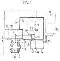
- the washing apparatus comprises a base 1, a turntable 2, a holding unit 5, rollers 3 and 4, and rollers 6.
- the turntable 2 is disposed on the base 1.
- a molding die "W” for a cold box process is placed on the turntable 2.
- the rollers 3 and 4 transfer the molding die “W” from the inside to the outside, or from the outside to the inside.
- Another molding die “W” is placed in the rear of the turntable 2, another molding die “W” which has been transferred by the rollers 3 and 4 previously.
- the rollers 6 transfer the molding die “W” to the holding unit 5 forward, or from the holding unit 5 rearward.
- the turntable 2, the rollers 3 and 4, and the rollers 6 herein constitute a transferring unit.
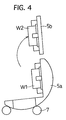
- the holding unit 5 includes a cradle 5a, and a cramp 5b.
- the cradle 5a holds a lower die “W1" of the molding die “W”.
- rollers 7 swing the cradle 5a in the counter clockwise direction in the drawing, thereby inverting the lower die “W1” by about 95 deg.
- the cramp 5b holds an upper die “W2" of the molding die “W”.
- a shaft (not shown) swings the cramp 5b in the clockwise direction in the drawing, thereby inverting the upper die "W2" by about 85 deg.
- a washing booth 8 is formed on one side of the holding unit 5.
- the washing booth 8 includes partition walls 7.
- the holding unit 5 is made movable in and out of the washing booth 8 by a carriage (not shown).
- a blowing robot 9 is held down from a ceiling in the washing booth 8.
- the blowing robot 9 works as a blowing unit.
- the robot 9 includes a robot arm 9a. In the robot arm 9a, there are disposed a direct injection nozzle 9b, a wide-angle nozzle 9c, and an air nozzle 9d.
- the direct injection nozzle 9b can blow washing water at a blowing angle of 0 deg.
- the wide-angle nozzle 9c can blow the washing water at a blowing angle of 90 deg. with respect to a molding surface of the molding die “W” by way of the control valve 10.
- the air nozzle 9d can blow highly pressurized air to a molding surface of the molding die “W” by way of an air supplying unit (shown in Fig. 2).
- the ceiling of the washing booth 8 is provided with a blower 11.
- the blower 11 can evacuate the steam, which results from the washing water, to the outside.
- the floor of the washing booth 8 is provided with a drain opening (not shown).
- the drain opening is connected with a dirty tank 13 by way of a pipe 12 and a filter (not shown).
- the filter has a mesh size of 40.
- the dirty tank 13 has a capacity of 120 L.
- the clean tank 14 has a capacity of 212 L.
- a cloth filter 13a is disposed between the dirty tank 13 and the clean tank 14, and is changeable one after another.
- the collected washing water is supplied from the dirty tank 13 to the clean tank 14 consecutively.
- a valve (not shown) is further disposed in a communication hole between the dirty tank 13 and clean tank 14. The valve opens the communication hole as the washing-water level decreases in the clean tank 14.
- the clean tank 14 originally holds the washing water including tap water therein.
- a temperature-controlling heater (not shown) is further disposed in the clean tank 14. The heater keeps the washing water held in the clean tank 14 at about 60 °C.
- the clean tank 14 is connected with a high-pressure plunger pump 16 by way of a pipe 15 and another filter. The high-pressure plunger pump 16 is provided for pressurizing and delivering the washing water.
- the high-pressure plunger pump 16 is connected with the control valve 10 so as to place its outlet aperture adjacent to a flame outlet aperture of a gas burner 17. Moreover, an air-pressurizing unit 18 (shown in Fig. 2) is further connected with the blowing robot 9 by way of another valve (shown in Fig. 2). The air-pressurizing unit 18 is provided to pressurize air to blow away the washing water.
- the dirty tank 13, and the clean tank 14 herein constitute a reservoir unit.
- the temperature-controlling heater, and the gas burner 17 herein constitute a heating unit.
- the high-pressure plunger pump 16 herein constitutes a washing-water pressurizing unit.
- the blower 11, the drain opening, the pipe 12, and the pipe 15 herein constitute a circulating unit.
- the filter cloth 13a, and the filter (not shown) herein constitute a filtering unit.
- the turntable 2, the rollers 3 and 4, and the rollers 6, constitute the transferring unit, and are connected with a controller 19 disposed in a control panel (not shown).
- the holding unit 5 is connected with the controller 19.
- the gas burner 17, etc., constitute the heating unit, and are connected with the controller 19.
- the high-pressure plunger pump 16 constitutes the washing-water pressurizing unit, and is connected with the controller 19.
- the control valve 10, the air-pressurizing unit 18, and the blowing robot 9 are connected with the controller 19.
- the controller 19 is further connected with an input unit 20 including switches.
- the thus constructed washing apparatus is used to wash the molding die "W”.
- the molding die "W” has been used to prepare a core by a cold box process.
- an operator places the molding die “W” on the rollers 3 by using a fork-lift truck.
- the rollers 3 are disposed on the turntable 2.
- the operator turns on the switches of the input unit 20. Consequently, the controller 19 actuates the washing apparatus to carry out the following operations in accordance with a predetermined program.
- a molding die “W” is transferred by the rollers 3 from the outside to the inside, and is turned by the turntable 2. Thereafter, the molding die “W” is transferred by the rollers 3 from the inside to the outside, and is further transferred by the rollers 6 to the holding unit 5 forward.
- the turntable 2 is thus turned, another molding die “W” can be placed on the rollers 4. Accordingly, while the molding die “W” is washed, the other molding die “W” can be put into a stand-by state for the next washing operation.
- the molding die "W” is opened. Specifically, the lower die “W1” is held by the cradle 5a, and the upper die “W2” is held and pulled up by the cramp 5b. Thereafter, as illustrated in Fig. 4, the lower die “W1” is inverted by about 95 deg, and the upper die “W2” is inverted by about 85 deg. While keeping the molding die “W” thus open, the holding unit 5 is moved into the washing booth 8.
- the washing water is blown by the blowing robot 9 to the molding surface of the opened molding die "W".
- the washing water is heated at a temperature of 70 °C or more, and is pressurized at a high pressure of 10 MPa or more.
- the wide-angle nozzle 9c blows the washing water at a broad angle to the spacious areas of the molding die “W” so as to remove the bonding agent, etc., in a short period of time; and the direct injection nozzle 9b blows the washing water at a narrow angle to the narrow areas of the molding die "W” so as to securely remove the bonding agent, etc.
- the opened molding die "W” is held and tilted by the holding unit 5.
- the washing water is inhibited from residing in the molding surface, and the fresh washing water is blown to the molding surface anew. Therefore, the temperature and pressure of the washing water can be maintained so that the bonding agent, etc., can be removed highly effectively.
- the narrow areas of the molding die "W" can be washed with ease.
- the blowing robot 9 can be inhibited from being immersed in the washing water, because it is held down from the ceiling. Hence, the blowing robot 9 can be inhibited from rusting.
- the highly pressurized air is blown to the molding surface of the molding die "W" by the air nozzle 9d.
- the air-pressurizing unit 18 pressurizes air to a high pressure. Consequently, the washing water is blown off from the molding surface. Thus, the molding surface can be inhibited from rusting.
- the washing water is collected into the dirty tank 13 by way of the drain opening and the pipe 12. Whilst, the steam resulting from the washing water is evacuated by the blower 11, and is also collected into the dirty tank 13. Then, the washing water is filtered by the filter cloth 13a and filter (not shown), and is recovered into the clean tank 14. Thereafter, the washing water is again heated by the temperature-controlling heater and gas burner 17, and is again highly pressurized by the high-pressure plunger pump 16. Finally, the washing water is reused for the washing operation. Hence, the washing water can be saved by recycling it.
- the washing process employing the washing apparatus of the Preferred Embodiment can shorten the time required for removing the bonding agent, etc. Since the washing process employs the washing water, the ejector pins, etc., of the molding die "W” are hardly affected adversely, the molding surface is little abraded, and the mesh, etc., provided for the vent hole are scarcely damaged. As a result, it is apparent that the washing process can wash the molding die "W" easily and fully.
- the washing apparatus of the Preferred Embodiment was adjusted so that it heated and blew the washing water at a temperature of 30 °C, 60 °C and 90 °C, respectively.
- the washability was inspected visually at 10 stages so as to determine the relationship between the temperature of the washing water and the washability.
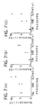
- the results are illustrated in Fig. 6. Note that, in Fig. 6, the mark “ ⁇ " specifies the results when the washing water was pressurized at 7.84 MPa and discharged in an amount of 5 L/min.; and the mark " ⁇ " specifies the results when the washing water was pressurized at 9.80 MPa and discharged in an amount of 10 L/min.
- Fig. 6 (A) shows the results of the washability evaluation for a vent hole provided with a mesh.
- Fig. 6 (B) shows the results of the washability evaluation for a vent hole provided with a slit.
- Fig. 6 (C) shows the results of the washability evaluation for a molding surface. Concerning the vent holes, the washability
- the washing apparatus of the Preferred Embodiment was adjusted so that it pressurized and blew the washing water at a pressure of 7.84 MPa, 9.80 MPa and 14.7 MPa, respectively.
- the washability was inspected visually at 10 stages so as to determine the relationship between the pressure of the washing water and the washability.
- the results are illustrated in Fig. 7. Note that, in Fig. 7, the mark “ ⁇ " specifies the results when the washing water was heated at 90 °C and discharged in an amount of 10 L/min.; and the mark " ⁇ " specifies the results when the washing water was heated at 60 °C and discharged in an amount of 5 L/min. Except for these testing conditions, Evaluation Test No. 2 was carried out in the same manner as Evaluation Test No. 1.
- the washing apparatus of the Preferred Embodiment was adjusted so that it discharged the washing water in an amount of 5 L/min., 10 L/min. and 12 L/min., respectively.
- the washability was inspected visually at 10 stages so as to determine the relationship between the discharge amount of the washing water and the washability.
- the results are illustrated in Fig. 8. Note that, in Fig. 8, the mark “ ⁇ " specifies the results when the washing water was pressurized at 7.84 MPa and heated at 90 °C; and the mark " ⁇ " specifies the results when the washing water was pressurized at 9.80 MPa and heated at 60 °C. Except for these testing conditions, Evaluation Test No. 3 was carried out in the same manner as Evaluation Test No. 1.
- a molding die for a cold box process is opened after usage. Washing water is heated at a temperature of 70 °C or more, and is blown to a molding surface of the molding die at a high pressure of 10 MPa or more.
- the cold-box-process molding die can be washed by this process easily and fully.
Landscapes
- Engineering & Computer Science (AREA)
- Manufacturing & Machinery (AREA)
- Mechanical Engineering (AREA)
- Chemical & Material Sciences (AREA)
- Composite Materials (AREA)
- Materials Engineering (AREA)
- Body Structure For Vehicles (AREA)
- Laminated Bodies (AREA)
- Motor Or Generator Frames (AREA)
- Iron Core Of Rotating Electric Machines (AREA)
- Powder Metallurgy (AREA)
- Cleaning By Liquid Or Steam (AREA)
- Connection Of Motors, Electrical Generators, Mechanical Devices, And The Like (AREA)
Abstract
Description
- The present invention relates to a process for washing a molding die for preparing a casting die (or core), and an apparatus therefor. In particular, the casting die (or core) is prepared by a cold box process.
- In a cold box process, a mixture of a phenol resin composition and a polyisocyanate is compounded with a casting silica sand to prepare a casting sand. The resulting casting sand is filled in a molding die. Then, a TEA (i.e., triethylamine) gas is introduced into the molding die. Accordingly, a polyurethane resin arises to work as a bonding agent. The bonding agent can be cured at an ordinary temperature. Thus, a casting die (or core) can be prepared precisely in accordance with a cavity of the molding die. After molding the casting die by the cold box process, the bonding agent and silica sand reside on a molding surface and in a vent hole. The molding surface forms the cavity, and the vent holes are opened in the molding surface. Consequently, it is necessary to remove the bonding agent and silica sand when another high-quality casting dies should be molded by reusing the molding die.
- Conventionally, the following 3 washing processes have been employed to wash the molding die:
- (a) brushing the molding die with a metallic brush together with an organic solvent;
- (b) blowing the molding die with highly pressurized air together with an organic solvent; and
- (c) blowing the molding die with shot particles made from glass or stainless steel, or with sand.
-
- However, it is difficult to remove the bonding agent and silica sand from the molding die by the aforementioned conventional washing processes. Especially, it is difficult to remove them from narrow or congested areas. Accordingly, it is necessary to manually carry out the washing operation by an operator. In addition, it is needed to frequently carry out the removing operation, and it is inevitable that the time required for the operation should be prolonged. Moreover, even if an organic solvent is used in the conventional washing processes, the organic solvent might adversely affect ejector pins, etc., of the molding die, depending on the types of the organic solvent employed.
- In particular, the vent hole cannot be processed effectively by the first and second conventional washing processes (a) and (b). Even if the vent holes are processed by the third conventional washing process (c), the molding surface around the vent hole might be damaged, and a mesh, which is usually provided for the vent hole, might be damaged. Moreover, the mesh might make it difficult to recover the glass particles, etc. Consequently, the mesh, etc., should be replaced with new ones regularly under the current circumstances.
- The US-A-5,544,667 discloses an apparatus for cleaning molds during the manufacture of shells or core packets that are ready for casting, by means of core shooters or shooting stations including a flushing system incorporating nozzles to spray or blast a tool set with circulating water.
- The JP-A-58173077 discloses a method for cleaning the inside of a casting mold easily without generating dust, by spraying high-pressure water to the inside surface of the casting mold after parting, and removing the parting material.
- The JP-A-07136602 discloses a method for cleaning a mold by jets of high-pressure water through a jetting nozzle under a discharge pressure of 3500 kgf/cm2, such removing foreign matter stuch on the internal surface of a stained mold.
- The present invention has been developed in view of the aforementioned circumstances. It is therefore an object of the present invention to provide a process and an apparatus for washing a molding die for a cold box process easily and fully.
- The inventors of the present invention made research and development extensively in order to achieve the object. First of all, they started investigating the chemical processes (1) through (21) as listed in Table 1 through Table 1 (sexies) below, and the physical processes (22) through (31) as listed in Table 2 through Table 2 (quarter) below.
Chemical Washing Water Soluble Washing Agent (1) Pure Water or Ultra-pure Water (2) Alkali Aqueous Solution (3) Surfactant Aqueous Solution (4) Surfactant/Alkali Combined Aqueous Solution (5) Surfactant/Organic Solvent Combined Aqueous Solution Chemical Washing Organic Solvent Washing Agent (6) Chlorinated Solvent (7) Hydrocarbon-based Solvent (8) Silicone-based Solvent (9) Alcohol-based Solvent Chemical Washing Washing Mode (10) Electrolysis Washing with Alkali Aqueous Solution (11) Ultrasonic Washing (12) Rotary Brush Washing (13) Immersion-oscillation Washing (14) Spraying Washing (15) Bubbling Washing Heating Conduction Heat (16) Combustion Mode (17) Steam Mode Heating Radiation Heat (18) UV Light Mode (19) Plasma Mode Chemical Reaction Oxidation (20) Dry Ozone Oxidation Mode (21) Wet Ozone Oxidation Mode Physical Washing by Shots Permanent Solid (22) Sand (23) Plastic Particles (23) Glass Particles (24) Stainless Steel Particles Physical Washing by Shots Disappearing Substance (26) Dry Ice (27) Air Physical Washing by Shots Water-related Substance (28) Ice (29) Highly-pressurized Water Physical Washing by Brush Washing Mode (30) Jet-like-propelled Chisel (31) Electromotive Brush - Chemical processes (1) through (21), and physical processes (22) through (31) were evaluated in terms of quality, difficulty, washability, cost and safety. They were graded as "Excellent", "Good", "Fair" or "Poor" for the characteristics, and were rated in terms of overall performance as well. Note that, in the evaluation, the quality was determined based on the presence of abrasion, etc., on a molding surface of a molding die, and the quality resulted in the superiority or inferiority of a resulting casting die. The casting die was prepared herein by the molding die which had been subjected to the washing processes. Table 3 below summarizes the results of the evaluation on the chemical processes (1) through (21). Table 4 below summarizes the results of the evaluation on the physical processes (22) through (31).
Quality Difficulty Washability Cost Safety Overall Evaluation (1) Fair Excellent Poor Excellent Excellent Fair (2) Fair Excellent Good Good Fair Good (3) Fair Good Fair Good Good Fair (4) Fair Good Fair Fair Fair Fair (5) Good Good Good Fair Fair Fair (6) Poor Good Good Fair Poor Fair (7) Good Good Good Fair Fair Good (8) Good Good Fair Poor Fair Poor (9) Good Good Fair Fair Fair Fair (10) Fair Fair Fair Fair Fair Fair (11) Good Good Good Poor Good Good (12) Fair Fair Fair Poor Fair Poor (13) Good Good Fair Fair Fair Good (14) Good Good Fair Fair Fair Good (15) Good Good Fair Fair Good Good (16) Poor Excellent Excellent Good Poor Poor (17) Fair Excellent Fair Good Good Good (18) Fair Good Fair Poor Fair Fair (19) Poor Fair Poor Poor Poor Poor (20) Good Fair Fair Poor Poor Fair (21) Fair Fair Good Poor Poor Fair Quality Difficulty Washability Cost Safety Overall Evaluation (22) Poor Excellent Good Good Fair Fair (23) Poor Good Poor Poor Good Poor (24) Fair Fair Fair Fair Good Fair (25) Poor Good Fair Good Good Fair (26) Excellent Fair Good Fair Good Good (27) Good Excellent Poor Fair Good Fair (28) Poor Poor Good Good Good Fair (29) Fair Good Fair Good Good Good (30) Poor Fair Fair Good Good Fair (31) Poor Fair Fair Good Good Fair - In physical process (26), the dry ice was blown to the molding surface at a high pressure. Physical process (26) was graded as "Excellent", because no problem arose in the molding surface. However, the mesh provided for the vent hole were damaged, and should be replaced with a new one.
- Further, in order to investigate the washing agent in detail, the inventors of the present invention examined a washing agent "TOYOKNOCK" produced by TOYOTA KAGAKU KOGYO CO., LTD. The washing agent worked as an alkali aqueous washing liquid. Furthermore, the present inventors examined hexane, toluene, dichloromethane, heptane, methanol and acetone. The hexane and heptane worked as a paraffin-based organic solvent. The toluene worked as an aromatic organic solvent. The dichloromethane worked as a chlorinated hydrocarbon organic solvent. The methanol worked as an alcohol-based organic solvent. The acetone worked as a ketone-based organic solvent. Among the aforementioned organic solvents, the hexane showed somewhat satisfactory results in terms of the washing ability for the molding surface when it is pressurized to a pressure exerted by an ordinary shower. However, the hexane showed still unsatisfactory results in terms of the washing ability for the vent hole. Note that the aforementioned organic solvents are quite unsatisfactory in terms of the safety because they were poisonous or dangerous substances.
- Hence, the inventors of the present invention aimed at making the pure water or ultra-pure water as a washing liquid. They further continued research and development to give the pure water or ultra-pure water general purpose applicability more. As a result, they completed the present invention as hereinafter described.
- A washing process according to the present invention comprises the step of:
- opening a molding die for a cold box process after usage, the molding die including a molding surface, and blowing washing water to the molding surface at a high pressure of 10 MPa or more, the washing water heated at a temperature of 70 °C or more.
-
- In the present washing process, distilled water, tap water and tap water containing a rust prevention agent can be used as the washing water. It is preferred to recycle the washing water by collecting and filtering the washing water after the blowing operation.
- Since the present washing process employs the washing water, the narrow areas of the molding die can be washed with ease. When carrying out the present washing process, the washing water is heated at a temperature of 70 °C or more and blown at a high pressure of 10 MPa or more. As a result, the bonding agent and silica sand can be removed remarkably effectively. The advantage can be verified by the evaluation tests carried out by the present inventors. Thus, the present washing process is practical. In the present washing process, it is preferred to heat the washing water at a temperature of from 70 to 90 °C, and to blow the washing water at a high pressure of from 10 to 15 MPa.
- Accordingly, the present washing process can shorten the time required for removing the bonding agent and silica sand, and can easily automate the removing operation by using a robot, etc. The washing water employed by the present washing process hardly affects the ejector pins, etc., of the molding die adversely, little abrades the molding surface and scarcely damages the mesh provided for the vent hole. Moreover, the washing water can be collected with ease.
- In a further aspect of the present washing process, the opened molding die can preferably be tilted, thereby inhibiting the washing water from residing in the molding surface. With this arrangement, the washing water can be inhibited from blowing to the molding surface in which the washing water is resided. Consequently, the fresh washing water can be blown to the molding surface anew. Thus, the temperature and pressure of the washing water can be maintained so that the bonding agent and silica sand can be removed highly effectively.
- In a further aspect of the present washing process, the washing water can preferably be blown to the molding surface of the opened molding die at varying blowing angles. The molding surface is formed as a variety of configurations corresponding to a diversity of casting dies. Accordingly, with this arrangement, the washing water can be blown to spacious areas of the molding die at a wide angle so that the bonding agent, etc., can be removed in a shortened period of time. In addition, the washing water can be blown to narrow areas of the molding die at a narrow angle so that the bonding agent, etc., can be removed securely.
- The present washing process can preferably further comprise the step of blowing highly pressurized air to the molding surface of the opened molding die after blowing the washing water thereto. With this arrangement, the washing water little resides in the molding surface. Consequently, the molding surface can be inhibited from rusting.
- In a further aspect of the present washing process, the washing water can preferably be recycled after washing the molding surface of the opened molding die, and can preferably be filtered to reuse for the washing process. With this arrangement, the washing water can be saved by recycling it.
- A washing apparatus according to the present invention comprises:
- a holding unit for holding an opened molding die for a cold box process after usage therein, the molding die including a molding surface;
- a reservoir unit for reserving washing water therein;
- a heating unit for heating the washing water reserved in the reservoir unit;
- a pressurizing unit for pressuring the washing water reserved in the reservoir unit;
- a blowing unit for blowing the washing water to the molding surface of the molding die held in the holding unit, the washing water heated at a temperature of 70 °C or more and pressurized to a high pressure of 10 MPa or more, the blowing unit connected with the reservoir unit;
- a circulating unit for collecting the washing water after the blowing operation and circulating the washing water to the reservoir unit; and
- a filtering unit for filtering the washing water after the blowing operation.
-
- In a further aspect of the present washing apparatus, the blowing unit can preferably be held down from a ceiling. The highly pressurized washing water reflects back from the molding surface, and accordingly is likely to reside under the blowing unit as well. Hence, when the blowing unit is held down from a ceiling, the blowing unit is hardly immersed in the washing water. Consequently, the blowing unit can be inhibited from rusting.
- As having described so far, in accordance with the present washing process and washing apparatus, the cold-box-process molding die can be washed easily and fully.
- A more complete appreciation of the present invention and many of its advantages will be readily obtained as the same becomes better understood by reference to the following detailed description when considered in connection with the accompanying drawings and detailed specification, all of which forms a part of the disclosure:
- Fig. 1 illustrates a washing apparatus of a Preferred Embodiment according to the present invention, and is a schematic plan view for showing the washing apparatus partly in horizontal cross-section;
- Fig. 2 illustrates the washing apparatus of the Preferred Embodiment, and is a schematic block diagram for showing the constituent units of the washing apparatus;
- Fig. 3 illustrates the washing apparatus of the Preferred Embodiment, and is a schematic side view for showing a holding unit of the washing apparatus in the course of opening a molding die;
- Fig. 4 illustrates the washing apparatus of the Preferred Embodiment, and is a schematic side view for showing the holding unit which holds the opened molding die;
- Fig. 5 illustrates the washing apparatus of the Preferred Embodiment, and is a schematic side view for showing a blowing unit of the washing apparatus;
- Fig. 6 illustrates the results of Evaluation Test No. 1, wherein:
- Fig. 6 (A) is a scatter diagram for showing the relationship between the temperature of the washing water and the washability for a vent hole provided with a mesh;
- Fig. 6 (B) is a scatter diagram for showing the relationship between the temperature of the washing water and the washability for a vent hole provided with a slit; and
- Fig. 6 (C) is a scatter diagram for showing the relationship between the temperature of the washing water and the washability for a molding surface;
- Fig. 7 illustrates the results of Evaluation Test No. 2, wherein:
- Fig. 7 (A) is a scatter diagram for showing the relationship between the pressure of the washing water and the washability for a vent hole provided with a mesh;
- Fig. 7 (B) is a scatter diagram for showing the relationship between the pressure of the washing water and the washability for a vent hole provided with a slit; and
- Fig. 7 (C) is a scatter diagram for showing the relationship between the pressure of the washing water and the washability for a molding surface; and
- Fig. 8 illustrates the results of Evaluation Test No. 3, wherein:
- Fig. 8 (A) is a scatter diagram for showing the relationship between the discharge amount of the washing water and the washability for a vent hole provided with a mesh;
- Fig. 8 (B) is a scatter diagram for showing the relationship between the discharge amount of the washing water and the washability for a vent hole provided with a slit; and
- Fig. 8 (C) is a scatter diagram for showing the relationship between the discharge amount of the washing water and the washability for a molding surface.
-
- Having generally described the present invention, a further understanding can be obtained by reference to the specific preferred embodiments which are provided herein for the purpose of illustration only and not intended to limit the scope of the appended claims.
- The present invention will be hereinafter described in detail with reference to a Preferred Embodiment exemplifying the present invention, the results of Evaluation Test Nos. 1 through 3 and the accompanying drawings.
- First of all, a washing apparatus of a Preferred Embodiment according to the present will be described in detail. As illustrated in Fig. 1, the washing apparatus comprises a base 1, a
turntable 2, a holdingunit 5,rollers rollers 6. Theturntable 2 is disposed on the base 1. A molding die "W" for a cold box process is placed on theturntable 2. Therollers turntable 2, another molding die "W" which has been transferred by therollers rollers 6 transfer the molding die "W" to the holdingunit 5 forward, or from the holdingunit 5 rearward. Theturntable 2, therollers rollers 6 herein constitute a transferring unit. - As illustrated in Figs. 3 and 4, the holding
unit 5 includes acradle 5a, and acramp 5b. Thecradle 5a holds a lower die "W1" of the molding die "W". As shown in Fig. 4,rollers 7 swing thecradle 5a in the counter clockwise direction in the drawing, thereby inverting the lower die "W1" by about 95 deg. Thecramp 5b holds an upper die "W2" of the molding die "W". As shown in Fig. 4, a shaft (not shown) swings thecramp 5b in the clockwise direction in the drawing, thereby inverting the upper die "W2" by about 85 deg. - As illustrated in Fig. 1, a
washing booth 8 is formed on one side of the holdingunit 5. Thewashing booth 8 includespartition walls 7. The holdingunit 5 is made movable in and out of thewashing booth 8 by a carriage (not shown). As shown in Fig. 5, a blowingrobot 9 is held down from a ceiling in thewashing booth 8. The blowingrobot 9 works as a blowing unit. Therobot 9 includes arobot arm 9a. In therobot arm 9a, there are disposed adirect injection nozzle 9b, a wide-angle nozzle 9c, and anair nozzle 9d. Thedirect injection nozzle 9b can blow washing water at a blowing angle of 0 deg. with respect to a molding surface of the molding die "W" by way of a control valve 10 (shown in Fig. 2). The wide-angle nozzle 9c can blow the washing water at a blowing angle of 90 deg. with respect to a molding surface of the molding die "W" by way of thecontrol valve 10. Theair nozzle 9d can blow highly pressurized air to a molding surface of the molding die "W" by way of an air supplying unit (shown in Fig. 2). - Further, as illustrated in Fig. 1, the ceiling of the
washing booth 8 is provided with ablower 11. Theblower 11 can evacuate the steam, which results from the washing water, to the outside. The floor of thewashing booth 8 is provided with a drain opening (not shown). The drain opening is connected with adirty tank 13 by way of apipe 12 and a filter (not shown). The filter has a mesh size of 40. Thedirty tank 13 has a capacity of 120 L. In thedirty tank 13, the oil is separated from the washing water. Thedirty tank 13 is connected with aclean tank 14. Theclean tank 14 has a capacity of 212 L. Acloth filter 13a is disposed between thedirty tank 13 and theclean tank 14, and is changeable one after another. Accordingly, the collected washing water is supplied from thedirty tank 13 to theclean tank 14 consecutively. A valve (not shown) is further disposed in a communication hole between thedirty tank 13 andclean tank 14. The valve opens the communication hole as the washing-water level decreases in theclean tank 14. Theclean tank 14 originally holds the washing water including tap water therein. A temperature-controlling heater (not shown) is further disposed in theclean tank 14. The heater keeps the washing water held in theclean tank 14 at about 60 °C. Theclean tank 14 is connected with a high-pressure plunger pump 16 by way of apipe 15 and another filter. The high-pressure plunger pump 16 is provided for pressurizing and delivering the washing water. The high-pressure plunger pump 16 is connected with thecontrol valve 10 so as to place its outlet aperture adjacent to a flame outlet aperture of agas burner 17. Moreover, an air-pressurizing unit 18 (shown in Fig. 2) is further connected with the blowingrobot 9 by way of another valve (shown in Fig. 2). The air-pressurizing unit 18 is provided to pressurize air to blow away the washing water. Thedirty tank 13, and theclean tank 14 herein constitute a reservoir unit. The temperature-controlling heater, and thegas burner 17 herein constitute a heating unit. The high-pressure plunger pump 16 herein constitutes a washing-water pressurizing unit. Theblower 11, the drain opening, thepipe 12, and thepipe 15 herein constitute a circulating unit. Thefilter cloth 13a, and the filter (not shown) herein constitute a filtering unit. - As illustrated in Fig. 2, the
turntable 2, therollers rollers 6, constitute the transferring unit, and are connected with acontroller 19 disposed in a control panel (not shown). The holdingunit 5 is connected with thecontroller 19. Thegas burner 17, etc., constitute the heating unit, and are connected with thecontroller 19. The high-pressure plunger pump 16 constitutes the washing-water pressurizing unit, and is connected with thecontroller 19. Likewise, thecontrol valve 10, the air-pressurizing unit 18, and the blowingrobot 9 are connected with thecontroller 19. Thecontroller 19 is further connected with aninput unit 20 including switches. - The thus constructed washing apparatus is used to wash the molding die "W". The molding die "W" has been used to prepare a core by a cold box process. At first, as illustrated in Fig. 1, an operator places the molding die "W" on the
rollers 3 by using a fork-lift truck. Therollers 3 are disposed on theturntable 2. Then, the operator turns on the switches of theinput unit 20. Consequently, thecontroller 19 actuates the washing apparatus to carry out the following operations in accordance with a predetermined program. - First of all, a molding die "W" is transferred by the
rollers 3 from the outside to the inside, and is turned by theturntable 2. Thereafter, the molding die "W" is transferred by therollers 3 from the inside to the outside, and is further transferred by therollers 6 to the holdingunit 5 forward. When theturntable 2 is thus turned, another molding die "W" can be placed on therollers 4. Accordingly, while the molding die "W" is washed, the other molding die "W" can be put into a stand-by state for the next washing operation. - Then, as illustrated in Fig. 3, the molding die "W" is opened. Specifically, the lower die "W1" is held by the
cradle 5a, and the upper die "W2" is held and pulled up by thecramp 5b. Thereafter, as illustrated in Fig. 4, the lower die "W1" is inverted by about 95 deg, and the upper die "W2" is inverted by about 85 deg. While keeping the molding die "W" thus open, the holdingunit 5 is moved into thewashing booth 8. - Further, the washing water is blown by the blowing
robot 9 to the molding surface of the opened molding die "W". As earlier mentioned, the washing water is heated at a temperature of 70 °C or more, and is pressurized at a high pressure of 10 MPa or more. In the washing-water blowing operation, the wide-angle nozzle 9c blows the washing water at a broad angle to the spacious areas of the molding die "W" so as to remove the bonding agent, etc., in a short period of time; and thedirect injection nozzle 9b blows the washing water at a narrow angle to the narrow areas of the molding die "W" so as to securely remove the bonding agent, etc. Moreover, the opened molding die "W" is held and tilted by the holdingunit 5. Consequently, the washing water is inhibited from residing in the molding surface, and the fresh washing water is blown to the molding surface anew. Therefore, the temperature and pressure of the washing water can be maintained so that the bonding agent, etc., can be removed highly effectively. Thus, by employing the thus arranged preferred washing apparatus or process of the present invention, the narrow areas of the molding die "W" can be washed with ease. In addition, the blowingrobot 9 can be inhibited from being immersed in the washing water, because it is held down from the ceiling. Hence, the blowingrobot 9 can be inhibited from rusting. - Furthermore, after the washing-water blowing operation, the highly pressurized air is blown to the molding surface of the molding die "W" by the
air nozzle 9d. As described above, the air-pressurizing unit 18 pressurizes air to a high pressure. Consequently, the washing water is blown off from the molding surface. Thus, the molding surface can be inhibited from rusting. - Moreover, after the washing operation, the washing water is collected into the
dirty tank 13 by way of the drain opening and thepipe 12. Whilst, the steam resulting from the washing water is evacuated by theblower 11, and is also collected into thedirty tank 13. Then, the washing water is filtered by thefilter cloth 13a and filter (not shown), and is recovered into theclean tank 14. Thereafter, the washing water is again heated by the temperature-controlling heater andgas burner 17, and is again highly pressurized by the high-pressure plunger pump 16. Finally, the washing water is reused for the washing operation. Hence, the washing water can be saved by recycling it. - As described so far, the washing process employing the washing apparatus of the Preferred Embodiment can shorten the time required for removing the bonding agent, etc. Since the washing process employs the washing water, the ejector pins, etc., of the molding die "W" are hardly affected adversely, the molding surface is little abraded, and the mesh, etc., provided for the vent hole are scarcely damaged. As a result, it is apparent that the washing process can wash the molding die "W" easily and fully.
- The washing apparatus of the Preferred Embodiment was adjusted so that it heated and blew the washing water at a temperature of 30 °C, 60 °C and 90 °C, respectively. The washability was inspected visually at 10 stages so as to determine the relationship between the temperature of the washing water and the washability. The results are illustrated in Fig. 6. Note that, in Fig. 6, the mark "×" specifies the results when the washing water was pressurized at 7.84 MPa and discharged in an amount of 5 L/min.; and the mark "" specifies the results when the washing water was pressurized at 9.80 MPa and discharged in an amount of 10 L/min. Fig. 6 (A) shows the results of the washability evaluation for a vent hole provided with a mesh. Fig. 6 (B) shows the results of the washability evaluation for a vent hole provided with a slit. Fig. 6 (C) shows the results of the washability evaluation for a molding surface. Concerning the vent holes, the washability was evaluated according to their opening degrees.
- It is understood from Fig. 6 that the higher the temperature of the washing water was, the better the washability was exhibited. According to the results of supplemental tests, etc., it was found practical when the washing water was heated at a temperature of 70 °C or more. The supplemental tests, etc., were carried out in addition to Evaluation Test No. 1.
- The washing apparatus of the Preferred Embodiment was adjusted so that it pressurized and blew the washing water at a pressure of 7.84 MPa, 9.80 MPa and 14.7 MPa, respectively. The washability was inspected visually at 10 stages so as to determine the relationship between the pressure of the washing water and the washability. The results are illustrated in Fig. 7. Note that, in Fig. 7, the mark "×" specifies the results when the washing water was heated at 90 °C and discharged in an amount of 10 L/min.; and the mark "" specifies the results when the washing water was heated at 60 °C and discharged in an amount of 5 L/min. Except for these testing conditions, Evaluation Test No. 2 was carried out in the same manner as Evaluation Test No. 1.
- It is understood from Fig. 7 that the higher the pressure of the washing water was, the better the washability was exhibited. According to the results of supplemental tests, etc., it was found practical when the washing water was pressurized at a pressure of 10 MPa or more. The supplemental tests, etc., were carried out in addition to Evaluation Test No. 2.
- The washing apparatus of the Preferred Embodiment was adjusted so that it discharged the washing water in an amount of 5 L/min., 10 L/min. and 12 L/min., respectively. The washability was inspected visually at 10 stages so as to determine the relationship between the discharge amount of the washing water and the washability. The results are illustrated in Fig. 8. Note that, in Fig. 8, the mark "×" specifies the results when the washing water was pressurized at 7.84 MPa and heated at 90 °C; and the mark "" specifies the results when the washing water was pressurized at 9.80 MPa and heated at 60 °C. Except for these testing conditions, Evaluation Test No. 3 was carried out in the same manner as Evaluation Test No. 1.
- It is understood from Fig. 8 that the smaller the discharge amount of the washing water was, the better the washability was exhibited.
- Having now fully described the present invention, it will be apparent to one of ordinary skill in the art that many changes and modifications can be made thereto without departing from the scope of the claims of the present invention.
- A molding die for a cold box process is opened after usage. Washing water is heated at a temperature of 70 °C or more, and is blown to a molding surface of the molding die at a high pressure of 10 MPa or more. The cold-box-process molding die can be washed by this process easily and fully.
Claims (10)
- A process for washing a molding surface of a die ("W") for a cold box process, comprising the step of:opening a molding die ("W") for a cold box process after usage, and blowing washing water to the molding surface at a high pressure of 10 MPa or more, the washing water heated at,a temperature of 70 °C or more.
- The process according to Claim 1, wherein the opened molding die (W1, W2) is tilted, thereby inhibiting the washing water from residing in the molding surface.
- The process according to Claim 1, wherein the washing water is blown to the molding surface of the opened molding die (W1, W2) at varying blowing angles.
- The process according to Claim 1 further comprising the step of blowing highly pressurized air to the molding surface of the opened molding die (W1, W2) after blowing the washing water thereto.
- The process according to Claim 1, wherein the washing water is recycled after washing the molding surface of the opened molding die (W1, W2), and is filtered to reuse for the washing process.
- An apparatus for washing a molding die ("W") for a cold box process, comprising:a holding unit (5) for holding an opened molding die (W1, W2) for a cold box process after usage therein, the molding die ("W") including a molding surface;a reservoir unit (13, 14) for reserving washing water therein;a heating unit (17) for heating the washing water reserved in said reservoir unit (13, 14);a pressurizing unit (16) for pressuring the washing water reserved in said reservoir unit (13, 14);a blowing unit (9) for blowing the washing water to the molding surface of the molding die ("W") held in said holding unit (5), the washing water heated at a temperature of 70 °C or more and pressurized to a high pressure of 10 MPa or more, the blowing unit (9) connected with said reservoir unit (13, 14);a circulating unit (11, 12, 15) for collecting the washing water after the blowing operation and circulating the washing water to said reservoir unit (13,14); anda filtering unit (13a) for filtering the washing water after the blowing operation.
- The apparatus according to Claim 6, wherein said blowing unit (9) is held down from a ceiling.
- The apparatus according to Claim 6, wherein said blowing unit (9) blows the washing water at varying blowing angles.
- The apparatus according to Claim 6 further comprising a unit (9d) for blowing highly pressurized air to the molding surface of the opened molding die (W1, W2) after blowing the washing water thereto.
- The apparatus according to Claim 6, wherein said holding unit (5) holds the opened molding die (W1, W2) in a tilted manner.
Applications Claiming Priority (2)
| Application Number | Priority Date | Filing Date | Title |
|---|---|---|---|
| DE29800005U | 1998-01-02 | ||
| DE29800005U DE29800005U1 (en) | 1998-01-02 | 1998-01-02 | Component, in particular body component for motor vehicles |
Publications (4)
| Publication Number | Publication Date |
|---|---|
| EP0927589A2 EP0927589A2 (en) | 1999-07-07 |
| EP0927589A3 EP0927589A3 (en) | 1999-07-21 |
| EP0927589B1 true EP0927589B1 (en) | 2002-09-04 |
| EP0927589B9 EP0927589B9 (en) | 2002-12-04 |
Family
ID=8050876
Family Applications (1)
| Application Number | Title | Priority Date | Filing Date |
|---|---|---|---|
| EP98122771A Expired - Lifetime EP0927589B9 (en) | 1998-01-02 | 1998-12-01 | Workpiece comprising a metal foam layer for the body of motor vehicles |
Country Status (3)
| Country | Link |
|---|---|
| EP (1) | EP0927589B9 (en) |
| AT (1) | ATE223275T1 (en) |
| DE (2) | DE29800005U1 (en) |
Families Citing this family (3)
| Publication number | Priority date | Publication date | Assignee | Title |
|---|---|---|---|---|
| PL193011B1 (en) * | 1999-06-23 | 2007-01-31 | Grillo Werke Ag | Zinc-based metal foamed bodies |
| DE102004040888A1 (en) * | 2004-08-24 | 2006-04-13 | Wilhelm Karmann Gmbh | Production of components with at least one metallic foam layer |
| DE102015002561A1 (en) * | 2015-02-27 | 2016-09-01 | Fraunhofer-Gesellschaft zur Förderung der angewandten Forschung e.V. | Method for producing a metallic composite body and metallic composite body |
Family Cites Families (4)
| Publication number | Priority date | Publication date | Assignee | Title |
|---|---|---|---|---|
| US4277544A (en) * | 1979-01-29 | 1981-07-07 | Ipm Corporation | Powder metallurgical articles and method of bonding the articles to ferrous base materials |
| JP3509031B2 (en) * | 1993-12-10 | 2004-03-22 | 片山特殊工業株式会社 | Method for manufacturing porous metal body with lead and porous metal body with lead manufactured by the method |
| AT405494B (en) * | 1996-02-14 | 1999-08-25 | Miba Frictec Gmbh | METHOD FOR PRODUCING A PLANE FRICTION BLADE |
| DE19612781C1 (en) * | 1996-03-29 | 1997-08-21 | Karmann Gmbh W | Component made of metallic foam material, process for final shaping of this component and device for carrying out the process |
-
1998
- 1998-01-02 DE DE29800005U patent/DE29800005U1/en not_active Expired - Lifetime
- 1998-12-01 EP EP98122771A patent/EP0927589B9/en not_active Expired - Lifetime
- 1998-12-01 AT AT98122771T patent/ATE223275T1/en not_active IP Right Cessation
- 1998-12-01 DE DE59805404T patent/DE59805404D1/en not_active Expired - Lifetime
Non-Patent Citations (1)
| Title |
|---|
| "Alulight-Platten", Prospekt der Firma Mepura GmbH, Juni 1996. * |
Also Published As
| Publication number | Publication date |
|---|---|
| EP0927589A2 (en) | 1999-07-07 |
| EP0927589A3 (en) | 1999-07-21 |
| EP0927589B9 (en) | 2002-12-04 |
| DE59805404D1 (en) | 2002-10-10 |
| DE29800005U1 (en) | 1999-05-06 |
| ATE223275T1 (en) | 2002-09-15 |
Similar Documents
| Publication | Publication Date | Title |
|---|---|---|
| US3702519A (en) | Method for the removal of unwanted portions of an article by spraying with high velocity dry ice particles | |
| EP0919311B1 (en) | Process for washing molding die for cold box process and washing apparatus therefor | |
| JP2011514863A (en) | Systems and devices for automatic built-in vehicle washing and other operations | |
| JP4538286B2 (en) | Mold cleaning method | |
| EP1498247B1 (en) | Rubber molded article vulcanizing mold | |
| JPH0796233B2 (en) | Water cleaning device for molding dies | |
| JP2005246652A (en) | Cleaning method of rubber vulcanizing mold | |
| JP6477426B2 (en) | Method for draining car wash machine and pump | |
| US20040104510A1 (en) | Method for manufacturing insert mold product | |
| JP2009154482A (en) | Mold washing method and mold washing apparatus | |
| KR101056527B1 (en) | Automatic tire cleaning rim of vulcanizer | |
| US5601102A (en) | Tote cleaning system | |
| JP2008023772A (en) | Apparatus for cleaning polyurethane mold and method for cleaning polyurethane mold | |
| JP3573450B2 (en) | Cleaning device and cleaning method for thin work | |
| JPS58161644A (en) | Car cleaning and waxing method | |
| JP2006062253A (en) | Mold cleaning method and apparatus | |
| JPH09248537A (en) | Tank cleaning system | |
| CN216504409U (en) | Cleaning system | |
| JP4273639B2 (en) | Cleaning method | |
| CN215513608U (en) | Vehicle rearview mirror cleaner | |
| JP3666127B2 (en) | Recycling method of electric dust collector | |
| KR200322558Y1 (en) | Non scratch cleaning Machine for the jet painting Bell-Cup. | |
| JP3002761U (en) | Cleaning equipment | |
| JPH06170854A (en) | Mold regeneration method | |
| JPH1110599A (en) | Washing device for water jet work piece |
Legal Events
| Date | Code | Title | Description |
|---|---|---|---|
| PUAI | Public reference made under article 153(3) epc to a published international application that has entered the european phase |
Free format text: ORIGINAL CODE: 0009012 |
|
| PUAL | Search report despatched |
Free format text: ORIGINAL CODE: 0009013 |
|
| AK | Designated contracting states |
Kind code of ref document: A2 Designated state(s): AT CH DE DK ES FI FR GB IT LI NL SE |
|
| AX | Request for extension of the european patent |
Free format text: AL;LT;LV;MK;RO;SI |
|
| AK | Designated contracting states |
Kind code of ref document: A3 Designated state(s): AT BE CH CY DE DK ES FI FR GB GR IE IT LI LU MC NL PT SE |
|
| AX | Request for extension of the european patent |
Free format text: AL;LT;LV;MK;RO;SI |
|
| 17P | Request for examination filed |
Effective date: 19991014 |
|
| AKX | Designation fees paid |
Free format text: AT CH DE DK ES FI FR GB IT LI NL SE |
|
| 17Q | First examination report despatched |
Effective date: 20010212 |
|
| GRAG | Despatch of communication of intention to grant |
Free format text: ORIGINAL CODE: EPIDOS AGRA |
|
| GRAG | Despatch of communication of intention to grant |
Free format text: ORIGINAL CODE: EPIDOS AGRA |
|
| GRAH | Despatch of communication of intention to grant a patent |
Free format text: ORIGINAL CODE: EPIDOS IGRA |
|
| GRAH | Despatch of communication of intention to grant a patent |
Free format text: ORIGINAL CODE: EPIDOS IGRA |
|
| GRAA | (expected) grant |
Free format text: ORIGINAL CODE: 0009210 |
|
| AK | Designated contracting states |
Kind code of ref document: B1 Designated state(s): AT CH DE DK ES FI FR GB IT LI NL SE |
|
| PG25 | Lapsed in a contracting state [announced via postgrant information from national office to epo] |
Ref country code: NL Free format text: LAPSE BECAUSE OF FAILURE TO SUBMIT A TRANSLATION OF THE DESCRIPTION OR TO PAY THE FEE WITHIN THE PRESCRIBED TIME-LIMIT Effective date: 20020904 Ref country code: FI Free format text: LAPSE BECAUSE OF FAILURE TO SUBMIT A TRANSLATION OF THE DESCRIPTION OR TO PAY THE FEE WITHIN THE PRESCRIBED TIME-LIMIT Effective date: 20020904 |
|
| REF | Corresponds to: |
Ref document number: 223275 Country of ref document: AT Date of ref document: 20020915 Kind code of ref document: T |
|
| REG | Reference to a national code |
Ref country code: GB Ref legal event code: FG4D Free format text: NOT ENGLISH |
|
| REG | Reference to a national code |
Ref country code: CH Ref legal event code: EP |
|
| REF | Corresponds to: |
Ref document number: 59805404 Country of ref document: DE Date of ref document: 20021010 |
|
| PG25 | Lapsed in a contracting state [announced via postgrant information from national office to epo] |
Ref country code: AT Free format text: LAPSE BECAUSE OF NON-PAYMENT OF DUE FEES Effective date: 20021201 |
|
| PG25 | Lapsed in a contracting state [announced via postgrant information from national office to epo] |
Ref country code: SE Free format text: LAPSE BECAUSE OF FAILURE TO SUBMIT A TRANSLATION OF THE DESCRIPTION OR TO PAY THE FEE WITHIN THE PRESCRIBED TIME-LIMIT Effective date: 20021204 Ref country code: DK Free format text: LAPSE BECAUSE OF FAILURE TO SUBMIT A TRANSLATION OF THE DESCRIPTION OR TO PAY THE FEE WITHIN THE PRESCRIBED TIME-LIMIT Effective date: 20021204 |
|
| GBT | Gb: translation of ep patent filed (gb section 77(6)(a)/1977) |
Effective date: 20021209 |
|
| PG25 | Lapsed in a contracting state [announced via postgrant information from national office to epo] |
Ref country code: LI Free format text: LAPSE BECAUSE OF NON-PAYMENT OF DUE FEES Effective date: 20021231 Ref country code: CH Free format text: LAPSE BECAUSE OF NON-PAYMENT OF DUE FEES Effective date: 20021231 |
|
| NLV1 | Nl: lapsed or annulled due to failure to fulfill the requirements of art. 29p and 29m of the patents act | ||
| ET | Fr: translation filed | ||
| PG25 | Lapsed in a contracting state [announced via postgrant information from national office to epo] |
Ref country code: ES Free format text: LAPSE BECAUSE OF FAILURE TO SUBMIT A TRANSLATION OF THE DESCRIPTION OR TO PAY THE FEE WITHIN THE PRESCRIBED TIME-LIMIT Effective date: 20030328 |
|
| PLBQ | Unpublished change to opponent data |
Free format text: ORIGINAL CODE: EPIDOS OPPO |
|
| PLBI | Opposition filed |
Free format text: ORIGINAL CODE: 0009260 |
|
| PLAX | Notice of opposition and request to file observation + time limit sent |
Free format text: ORIGINAL CODE: EPIDOSNOBS2 |
|
| 26 | Opposition filed |
Opponent name: ALULIGHT INTERNATIONAL GMBH Effective date: 20030604 |
|
| REG | Reference to a national code |
Ref country code: CH Ref legal event code: PL |
|
| PLAX | Notice of opposition and request to file observation + time limit sent |
Free format text: ORIGINAL CODE: EPIDOSNOBS2 |
|
| PLBB | Reply of patent proprietor to notice(s) of opposition received |
Free format text: ORIGINAL CODE: EPIDOSNOBS3 |
|
| PLAY | Examination report in opposition despatched + time limit |
Free format text: ORIGINAL CODE: EPIDOSNORE2 |
|
| PLAY | Examination report in opposition despatched + time limit |
Free format text: ORIGINAL CODE: EPIDOSNORE2 |
|
| PLAY | Examination report in opposition despatched + time limit |
Free format text: ORIGINAL CODE: EPIDOSNORE2 |
|
| PLAY | Examination report in opposition despatched + time limit |
Free format text: ORIGINAL CODE: EPIDOSNORE2 |
|
| PLBC | Reply to examination report in opposition received |
Free format text: ORIGINAL CODE: EPIDOSNORE3 |
|
| PLBP | Opposition withdrawn |
Free format text: ORIGINAL CODE: 0009264 |
|
| PLBD | Termination of opposition procedure: decision despatched |
Free format text: ORIGINAL CODE: EPIDOSNOPC1 |
|
| PLBM | Termination of opposition procedure: date of legal effect published |
Free format text: ORIGINAL CODE: 0009276 |
|
| STAA | Information on the status of an ep patent application or granted ep patent |
Free format text: STATUS: OPPOSITION PROCEDURE CLOSED |
|
| 27C | Opposition proceedings terminated |
Effective date: 20050922 |
|
| PGFP | Annual fee paid to national office [announced via postgrant information from national office to epo] |
Ref country code: IT Payment date: 20110326 Year of fee payment: 13 Ref country code: DE Payment date: 20110119 Year of fee payment: 13 |
|
| PGFP | Annual fee paid to national office [announced via postgrant information from national office to epo] |
Ref country code: FR Payment date: 20110629 Year of fee payment: 13 Ref country code: GB Payment date: 20110323 Year of fee payment: 13 |
|
| GBPC | Gb: european patent ceased through non-payment of renewal fee |
Effective date: 20111201 |
|
| REG | Reference to a national code |
Ref country code: FR Ref legal event code: ST Effective date: 20120831 |
|
| REG | Reference to a national code |
Ref country code: DE Ref legal event code: R119 Ref document number: 59805404 Country of ref document: DE Effective date: 20120703 |
|
| PG25 | Lapsed in a contracting state [announced via postgrant information from national office to epo] |
Ref country code: GB Free format text: LAPSE BECAUSE OF NON-PAYMENT OF DUE FEES Effective date: 20111201 Ref country code: DE Free format text: LAPSE BECAUSE OF NON-PAYMENT OF DUE FEES Effective date: 20120703 |
|
| PG25 | Lapsed in a contracting state [announced via postgrant information from national office to epo] |
Ref country code: IT Free format text: LAPSE BECAUSE OF NON-PAYMENT OF DUE FEES Effective date: 20111201 |
|
| PG25 | Lapsed in a contracting state [announced via postgrant information from national office to epo] |
Ref country code: FR Free format text: LAPSE BECAUSE OF NON-PAYMENT OF DUE FEES Effective date: 20120102 |