EP0926501A1 - In-line skate wheel mounting with rotational speed detection device - Google Patents
In-line skate wheel mounting with rotational speed detection device Download PDFInfo
- Publication number
- EP0926501A1 EP0926501A1 EP98403058A EP98403058A EP0926501A1 EP 0926501 A1 EP0926501 A1 EP 0926501A1 EP 98403058 A EP98403058 A EP 98403058A EP 98403058 A EP98403058 A EP 98403058A EP 0926501 A1 EP0926501 A1 EP 0926501A1
- Authority
- EP
- European Patent Office
- Prior art keywords
- wheel
- encoder
- sensor
- rolling
- axis
- Prior art date
- Legal status (The legal status is an assumption and is not a legal conclusion. Google has not performed a legal analysis and makes no representation as to the accuracy of the status listed.)
- Granted
Links
Images


Classifications
-
- F—MECHANICAL ENGINEERING; LIGHTING; HEATING; WEAPONS; BLASTING
- F16—ENGINEERING ELEMENTS AND UNITS; GENERAL MEASURES FOR PRODUCING AND MAINTAINING EFFECTIVE FUNCTIONING OF MACHINES OR INSTALLATIONS; THERMAL INSULATION IN GENERAL
- F16C—SHAFTS; FLEXIBLE SHAFTS; ELEMENTS OR CRANKSHAFT MECHANISMS; ROTARY BODIES OTHER THAN GEARING ELEMENTS; BEARINGS
- F16C13/00—Rolls, drums, discs, or the like; Bearings or mountings therefor
- F16C13/006—Guiding rollers, wheels or the like, formed by or on the outer element of a single bearing or bearing unit, e.g. two adjacent bearings, whose ratio of length to diameter is generally less than one
-
- G—PHYSICS
- G01—MEASURING; TESTING
- G01P—MEASURING LINEAR OR ANGULAR SPEED, ACCELERATION, DECELERATION, OR SHOCK; INDICATING PRESENCE, ABSENCE, OR DIRECTION, OF MOVEMENT
- G01P3/00—Measuring linear or angular speed; Measuring differences of linear or angular speeds
- G01P3/42—Devices characterised by the use of electric or magnetic means
- G01P3/44—Devices characterised by the use of electric or magnetic means for measuring angular speed
- G01P3/443—Devices characterised by the use of electric or magnetic means for measuring angular speed mounted in bearings
- G01P3/446—Devices characterised by the use of electric or magnetic means for measuring angular speed mounted in bearings mounted between two axially spaced rows of rolling elements
-
- G—PHYSICS
- G01—MEASURING; TESTING
- G01P—MEASURING LINEAR OR ANGULAR SPEED, ACCELERATION, DECELERATION, OR SHOCK; INDICATING PRESENCE, ABSENCE, OR DIRECTION, OF MOVEMENT
- G01P3/00—Measuring linear or angular speed; Measuring differences of linear or angular speeds
- G01P3/42—Devices characterised by the use of electric or magnetic means
- G01P3/50—Devices characterised by the use of electric or magnetic means for measuring linear speed
-
- F—MECHANICAL ENGINEERING; LIGHTING; HEATING; WEAPONS; BLASTING
- F16—ENGINEERING ELEMENTS AND UNITS; GENERAL MEASURES FOR PRODUCING AND MAINTAINING EFFECTIVE FUNCTIONING OF MACHINES OR INSTALLATIONS; THERMAL INSULATION IN GENERAL
- F16C—SHAFTS; FLEXIBLE SHAFTS; ELEMENTS OR CRANKSHAFT MECHANISMS; ROTARY BODIES OTHER THAN GEARING ELEMENTS; BEARINGS
- F16C2316/00—Apparatus in health or amusement
- F16C2316/30—Articles for sports, games and amusement, e.g. roller skates, toys
-
- F—MECHANICAL ENGINEERING; LIGHTING; HEATING; WEAPONS; BLASTING
- F16—ENGINEERING ELEMENTS AND UNITS; GENERAL MEASURES FOR PRODUCING AND MAINTAINING EFFECTIVE FUNCTIONING OF MACHINES OR INSTALLATIONS; THERMAL INSULATION IN GENERAL
- F16C—SHAFTS; FLEXIBLE SHAFTS; ELEMENTS OR CRANKSHAFT MECHANISMS; ROTARY BODIES OTHER THAN GEARING ELEMENTS; BEARINGS
- F16C41/00—Other accessories, e.g. devices integrated in the bearing not relating to the bearing function as such
- F16C41/004—Electro-dynamic machines, e.g. motors, generators, actuators
-
- F—MECHANICAL ENGINEERING; LIGHTING; HEATING; WEAPONS; BLASTING
- F16—ENGINEERING ELEMENTS AND UNITS; GENERAL MEASURES FOR PRODUCING AND MAINTAINING EFFECTIVE FUNCTIONING OF MACHINES OR INSTALLATIONS; THERMAL INSULATION IN GENERAL
- F16C—SHAFTS; FLEXIBLE SHAFTS; ELEMENTS OR CRANKSHAFT MECHANISMS; ROTARY BODIES OTHER THAN GEARING ELEMENTS; BEARINGS
- F16C41/00—Other accessories, e.g. devices integrated in the bearing not relating to the bearing function as such
- F16C41/007—Encoders, e.g. parts with a plurality of alternating magnetic poles
Definitions
- the present invention relates to the field of roller skates arranged on a line, a device for detecting the rotation of the wheels being expected.
- the inline skate wheels are mounted one behind the other on the lateral flanks of an integral plate of a shoe.
- Each wheel is rotatably mounted on a fixed axle by by means of two rolling bearings, said axis being secured by its ends at the sides of the plate.
- Document DE-U-297 08 535 relates to devices for instrumented inline skates.
- the rear wheel of a skate is equipped with a encoder scrolling in rotation in front of a sensor integral with a part non-rotating skate.
- the signal is processed and transmitted wirelessly to a bracelet display located on the skater's wrist.
- the speed detection device is particularly exposed to various pollutions by water, mud and other impurities. Skates are also subjected to shocks frequent caused by falls of the skater, crossings of sidewalks etc. The aforementioned document is silent on this subject.
- the object of the invention is therefore to solve the problem of protection of the sensor / encoder assembly which arises in this type of mounting.
- the invention also relates to a device for detecting the speed of rotation in which the elements comprising the means sensor and the encoder means replace original elements or are mount on original elements without requiring any modification of the wheel or original parts remaining in the wheel assembly.
- the equipment of a conventional skate with a system of detection according to the invention can therefore be carried out easily by the user, without requiring special skills or tools special.
- the device for detecting the speed of rotation of a wheel is intended for in-line skating.
- the wheel is supported by rotating outer rings of two rolling bearings. Rings fixed interior of the two rolling bearings are integral with an axis mounted on a plate.
- the detection device comprises means sensor and encoder means arranged in an axially delimited volume by the two rolling bearings and radially by a cylindrical surface coaxial with rolling bearings and of diameter equal to the diameters the outer rings of the rolling bearings. So the encoder is in an enclosure perfectly protected from the outside environment.
- the detection device can be easily adapted to an inline skate standard previously lacking detection means, by a simple interchangeability of elements or by mounting additional elements not requiring modification of the original parts of the skate. The detection device is therefore very easy to use.
- the encoder can be integrated in an encoder holder block secured to a rotating ring of a rolling bearing or fixed element.
- the encoder means is mounted on a fixed part of the wheel assembly.
- the encoder means is mounted on a rotating element of the wheel assembly.
- the encoder means can be mounted on a ring of one of the rolling bearings, for example instead a sealing member.
- the encoder means can be mounted in contact with the wheel bore.
- the encoder means may be integral with a spacer in the form of sleeve surrounding the axis and supporting the inner rings of the bearings rolling.
- the device detection comprises a sensor means arranged opposite the encoder means and secured to a fixed element of the wheel assembly when the encoder means is integral with a rotating element and integral with a rotating element when the encoder means is integral with a fixed element of the mounting of wheel.
- the sensor means can be placed in a housing arranged in the axis and may include a transmitter disposed at one end of said axis.
- the sensor means can be arranged in a block mounted on a ring of one of the rolling bearings, or on the axis between the two bearings bearing, or in the wheel bore.
- the sensor means can be in contact with radial surfaces of the two rolling bearings.
- the sensor means comprises a transmitter arranged in the block.
- a battery or a rotating generator To supply the transmitter, a battery or a rotating generator.
- the sensor means and the encoder means can be implemented keeping the wheel its original structure and shape.
- the invention also relates to an inline skate equipped with such a detection device.
- wheel 1 of an inline skate is provided with a bore 2 extending at each end by a cylindrical mounting surface 3 and 4 shouldered for rolling bearings 5 and 6.
- the two mounting surfaces 3 and 4 are concentric with the axis of wheel rotation and are of identical diameter, greater than the bore of the wheel 1.
- the rolling bearings 5 and 6 are identical and include a rotating outer ring 7 provided with a rolling track 8, a non-rotating inner ring 9 provided with a raceway 10 and a row of rolling elements 11, for example balls, arranged between track 8 and track 10 and kept spaced in the circumferential direction by a cage 12.
- each rolling bearing is mounted by means of its cylindrical outer surface 7a in the range corresponding cylindrical mounting 3 or 4 of the wheel 1.
- the wheel 1 is monobloc, bore 2 and the running surface forming part of it same room.
- the inner rings 9 of the rolling bearings 5 and 6 are supported by a sleeve-shaped spacer 13 provided at each end of a shouldered cylindrical seat 14 and 15 for mounting the bearings with bearings 5 and 6.
- the spacer 13 is integral with an axis 16 projecting from two sides of the spacer 13 and of the wheel 1. The portions of the axle which protrude from the spacer 13 pass through the bores 17 provided in each side 18 and 19 of a plate 20.
- the pin 16 is held in place by a side by a round head 21 and on the other side by a screw 22 which has been screwed at the end of the axis 16 and which is provided with a wide head 23 of diameter greater than that of the bore 17 of the flank 19 of the plate 20 and coming bear against a radial surface of said sidewall 19 thus blocking the axis 16.
- Rolling bearing 6 is provided on each side of the row rolling elements 11 of seals 24 and 25.
- the seal seal 24 is arranged on the outside while the packing 25 is arranged on the inner side and faces the bearing bearing 5.
- the rolling bearing 5 is also provided with a seal 26 outer seal but has no seal interior. Indeed, this is replaced by an encoder holder block 27, made of synthetic material secured to the outer ring 7 of the rolling bearing 5 identical to the packing sealing 26, that is to say by hooking in a groove 28 of the outer ring 7 near the raceway 8.
- An encoder 29 supported by the encoder holder block 27 is disposed radially at a short distance from the spacer 13.
- the encoder 29 is located thus arranged axially between the rolling bearings 5 and 6, inside of a volume delimited radially by the outer surfaces 7a of outer rings 7 and the bore of the inner rings 9.
- the door unit encoder 27 is not in contact with the bore 2 of the wheel 1 which facilitates the installation of the rolling bearing 6 provided with its encoder holder block 27 in wheel 1 or the reverse disassembly operation.
- a sensor 30 is arranged integral with a fixed part of the shoe, in look of the encoder 29 and radially inside the latter. If the encoder 29 is of the magnetic type, a magnetosensitive sensor 30 is used, for example a Hall effect probe.
- the sensor 30 is arranged in a groove 31 formed axially in the axis 16. The groove 31 is arranged on the cylindrical outer surface of axis 16 and extends axially between the head 21 of axis 16 and substantially the level of encoder 29 so as to place the sensor 30 in the same radial plane as the encoder 29.
- the spacer 13 will be made of a non-magnetic material for let the magnetic field lines pass freely between the sensor and the encoder.
- the sensor 30 is connected by a connection cable 32 arranged in the groove 31 to an emitter 33 housed in the round head 21 of the axis 16 and powered by a battery 34 also placed in the round head 21.
- the transmitter 33 is capable of transmitting the signal emitted by the sensor 30 to a receiver which can be carried by the skater himself for example on the wrist or on a fixed station on the edge of a runway skating.
- the battery 34 is used to power not only the transmitter 33 but also of the sensor 30 if the latter is of the active type.
- Head 21 of axis 16 can be made of plastic material overmolded on a disc 35 forming a flat head of the axis 16.
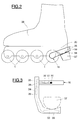
- FIG 2 there is shown schematically a shoe in line comprising a shoe 36 resting on a plate 20 fitted with four wheels 1 with parallel and aligned axes, and arranged in the same plane equatorial.
- the rear wheel 1 is equipped with an axle 16 of a slightly different from that of figure 1.
- the axis 16 extends from the disc 35 by an arm made of plastic overmolded on said disc 35.
- the arm 36 extends towards the rear of the skate, going up slightly and comes to bear on and behind a brake heel 37 disposed at the rear of the wheels 1 and allowing the skater to brake.
- the arm 36 thus comprises a first portion 38 extending backwards and a second transverse portion 39 extending from the free end of the first portion 38 and coming in contact with the brake heel 37.
- Such an axis makes it possible to have more place to house transmitter 33 and battery 34 and is suitable for transmission more significant than the transmission obtained with the configuration illustrated in figure 1.
- the wheel 1 has a structure identical to that of FIG. 1 but the encoder 29 is integral with the spacer 13 and flush with an outer cylindrical surface of the spacer 13 between the two rolling bearings 5 and 6.
- the sensor 30 is supported by a sensor holder block 40 and is arranged radially in look and at a short distance from the encoder 29.
- the sensor holder block 40 is made radially of synthetic material and is in contact with the bore 2 of the wheel 1 and with the internal radial front surfaces 7b rotating outer rings 7 of the rolling bearings 5 and 6.
- the transmitter 33 and the battery 34 are integrated in the sensor holder block 40.
- the equipment of one of the wheels 1 with a device detecting the speed of rotation is extremely easy. Simply dismantle the original rolling bearings 5 and 6 and reassemble them (or reassemble new bearings) after having placed in bore 2 of the wheel 1 the annular block 40 comprising the sensor 30, the transmitter 33 and the battery 34 and have replaced the original spacer with a spacer 13 comprising an encoder 29 such as a magnet.
- Wheel 1 does not undergo any modification and keeps fully its original structure and form.
- the rolling bearing 5 is provided with two seals 26 and 41.
- the sensor-encoder assembly is arranged in a cylindrical volume of radial dimension smaller than that delimited by the cylindrical outer surfaces 7a, and centered on the axis rolling bearings.
- the wheel 1 has a structure identical to that of FIG. 1.
- the bearings at bearing 5 and 6 are directly mounted on axis 16.
- the encoder holder block 27 is close to that of FIG. 1, its dimensions having only been slightly reduced.
- the sensor holder block 42 is mounted on the axis 16 and is placed axially in contact with the inner rings 9 of the bearings bearing 5 and 6 for which it acts as an axial spacer.
- the block sensor holder 42 also includes the transmitter 33 and the battery 34.
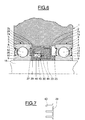
- FIGS. 6 and 7 The embodiment illustrated in FIGS. 6 and 7 is close to the previous, except that the encoder 29 has the shape of a comb whose teeth 43 scroll in rotation in front of the sensor 30, the encoder 29 being made of magnetic material.
- the sensor / encoder assembly is of the passive type and includes a fixed sensor comprising an annular winding 44 wound on the branch axial view of a L-section flow concentrator 45 made of a material magnetic, said coil coming to bear axially against the radial branch of said concentrator, magnets 46 (or a multipolar magnetic ring) being arranged axially against the winding 44 and around the branch axial of the concentrator 45.
- the teeth 43 scroll in rotation in front of the poles of the magnets 46 and around the winding 44 of the sensor 30.
- the poles of the magnets 46 are either opposite the teeth 43 of the comb, or between two teeth of the comb.
- the magnetic field lines close around the winding 44 by performing a closed circuit between the magnet 46, the encoder 29, the flux concentrator 45 with return to the magnet 46.
- the flow lines do not close around the winding 44 because they are not channeled by the teeth of the comb.
- the variations of the magnetic fields thus created induce in coil 44 a current whose frequency is proportional to the encoder rotation speed 29.
- the signal as current electric can then be used for both speed information and for the generation of energy to the transmitter 33.
- This mode of therefore does not require an electrical supply battery since it is the sensor-encoder assembly which functions as a generator of electricity, the stator of which consists of the sensor and the rotor of the coder.
- the sensor 30 and the associated transmitter 33 are housed in a block annular 47 secured to the fixed ring 9 of the bearing 5, the encoder assembly being secured to the rotating ring 7 (a reverse arrangement - block rotating sensor and fixed encoder assembly - being possible).
- the equipment of one of the wheels of a skate with a device for speed detection can be done by simple replacement of one of the original rolling bearings and spacer respectively by the bearing 5 provided with the encoder holder block 27 and by the sensor holder block 42.
- any wheel on the skate can be easily fitted with a wheel rotation parameter detection device.
- these embodiments are not limiting.
- Other types of sensors could be used. Thanks to the invention, there is a low cost and very high speed detection system high reliability thanks to the excellent protection of the device inside an enclosed space formed by the bore of the wheel, the axle and the two bearings rolling.
- the mounting of the device is particularly easy and can be done by simple exchange or addition of elements not requiring no modification of the wheel or original parts remaining in the wheel mounting.
- the device is particularly compact.
Abstract
Description
La présente invention concerne le domaine des patins à roues disposées sur une ligne, un dispositif de détection de la rotation des roues étant prévu.The present invention relates to the field of roller skates arranged on a line, a device for detecting the rotation of the wheels being expected.
D'une façon générale, les roues de patins en ligne sont montées les unes derrière les autres sur les flancs latéraux d'une platine solidaire d'une chaussure. Chaque roue est montée à rotation sur un axe fixe par l'intermédiaire de deux paliers à roulement, ledit axe étant solidarisé par ses extrémités aux flancs de la platine.In general, the inline skate wheels are mounted one behind the other on the lateral flanks of an integral plate of a shoe. Each wheel is rotatably mounted on a fixed axle by by means of two rolling bearings, said axis being secured by its ends at the sides of the plate.
Le document DE-U-297 08 535 concerne des dispositifs de patins en ligne instrumentés. La roue arrière d'un patin est équipée d'un codeur venant défiler à rotation devant un capteur solidaire d'une partie non tournante du patin. Le signal est traité et transmis sans fil à un bracelet d'affichage situé sur le poignet du patineur. Toutefois, les roues se trouvant au ras du sol, le dispositif de détection de la vitesse de rotation est particulièrement exposé aux pollutions diverses par l'eau, la boue et d'autres impuretés. Les patins sont également soumis à des chocs fréquents occasionnés lors des chutes du patineur, de franchissements de trottoirs etc. Le document précité est muet à ce sujet.Document DE-U-297 08 535 relates to devices for instrumented inline skates. The rear wheel of a skate is equipped with a encoder scrolling in rotation in front of a sensor integral with a part non-rotating skate. The signal is processed and transmitted wirelessly to a bracelet display located on the skater's wrist. However, the wheels being at ground level, the speed detection device is particularly exposed to various pollutions by water, mud and other impurities. Skates are also subjected to shocks frequent caused by falls of the skater, crossings of sidewalks etc. The aforementioned document is silent on this subject.
L'invention a donc pour objet de résoudre le problème de protection de l'ensemble capteur/codeur qui se pose dans ce type de montage.The object of the invention is therefore to solve the problem of protection of the sensor / encoder assembly which arises in this type of mounting.
L'invention a également pour objet un dispositif de détection de la vitesse de rotation dans lequel les éléments comportant le moyen capteur et le moyen codeur se substituent à des éléments d'origine ou se montent sur des éléments d'origine sans nécessiter aucune modification de la roue ou des pièces d'origine subsistant dans le montage de roue.The invention also relates to a device for detecting the speed of rotation in which the elements comprising the means sensor and the encoder means replace original elements or are mount on original elements without requiring any modification of the wheel or original parts remaining in the wheel assembly.
L'équipement d'un patin conventionnel avec un système de détection suivant l'invention peut donc être effectué aisément par l'utilisateur, sans nécessiter de compétence particulière ou d'outillage spécial.The equipment of a conventional skate with a system of detection according to the invention can therefore be carried out easily by the user, without requiring special skills or tools special.
Le dispositif de détection de la vitesse de rotation d'une roue, selon l'invention, est destiné à un patin en ligne. La roue est supportée par des bagues extérieures tournantes de deux paliers à roulement. Des bagues intérieures fixes des deux paliers à roulement sont solidaires d'un axe monté sur une platine. Le dispositif de détection comprend un moyen capteur et un moyen codeur disposés dans un volume délimité axialement par les deux paliers à roulement et radialement par une surface cylindrique coaxiale aux paliers à roulement et de diamètre égal aux diamètres extérieurs des bagues extérieures des paliers à roulement. Ainsi, le codeur se trouve dans une enceinte parfaitement protégée du milieu extérieur. Le dispositif de détection peut s'adapter facilement sur un patin en ligne standard dépourvu jusqu'alors de moyen de détection, par une simple interchangeabilité des éléments ou par montage d'éléments additionnels ne nécessitant pas de modification des pièces d'origine du patin. Le dispositif de détection est donc très facilement utilisable. Le codeur peut être intégré à un bloc porte codeur solidaire d'une bague tournante d'un palier à roulement ou d'un élément fixe.The device for detecting the speed of rotation of a wheel, according to the invention, is intended for in-line skating. The wheel is supported by rotating outer rings of two rolling bearings. Rings fixed interior of the two rolling bearings are integral with an axis mounted on a plate. The detection device comprises means sensor and encoder means arranged in an axially delimited volume by the two rolling bearings and radially by a cylindrical surface coaxial with rolling bearings and of diameter equal to the diameters the outer rings of the rolling bearings. So the encoder is in an enclosure perfectly protected from the outside environment. The detection device can be easily adapted to an inline skate standard previously lacking detection means, by a simple interchangeability of elements or by mounting additional elements not requiring modification of the original parts of the skate. The detection device is therefore very easy to use. The encoder can be integrated in an encoder holder block secured to a rotating ring of a rolling bearing or fixed element.
Dans un mode de réalisation de l'invention, le moyen codeur est monté sur un élément fixe du montage de roue.In one embodiment of the invention, the encoder means is mounted on a fixed part of the wheel assembly.
Dans un autre mode de réalisation, le moyen codeur est monté sur un élément tournant du montage de roue. Le moyen codeur peut être monté sur une bague de l'un des paliers à roulement, par exemple à la place d'un organe d'étanchéité. Le moyen codeur peut être monté en contact avec l'alésage de la roue.In another embodiment, the encoder means is mounted on a rotating element of the wheel assembly. The encoder means can be mounted on a ring of one of the rolling bearings, for example instead a sealing member. The encoder means can be mounted in contact with the wheel bore.
Le moyen codeur peut être solidaire d'une entretoise en forme de manchon entourant l'axe et supportant les bagues intérieures des paliers à roulement.The encoder means may be integral with a spacer in the form of sleeve surrounding the axis and supporting the inner rings of the bearings rolling.
Dans un mode de réalisation de l'invention, le dispositif de détection comprend un moyen capteur disposé en regard du moyen codeur et solidaire d'un élément fixe du montage de roue lorsque le moyen codeur est solidaire d'un élément tournant et solidaire d'un élément tournant lorsque le moyen codeur est solidaire d'un élément fixe du montage de roue. Le moyen capteur peut être disposé dans un logement aménagé dans l'axe et peut comprendre un émetteur disposé à une extrémité dudit axe. En variante, le moyen capteur peut être disposé dans un bloc monté sur une bague d'un des paliers à roulement, ou sur l'axe entre les deux paliers à roulement, ou dans l'alésage de la roue. Le moyen capteur peut être en contact avec des surfaces radiales des deux paliers à roulement. Avantageusement, le moyen capteur comprend un émetteur disposé dans le bloc.In one embodiment of the invention, the device detection comprises a sensor means arranged opposite the encoder means and secured to a fixed element of the wheel assembly when the encoder means is integral with a rotating element and integral with a rotating element when the encoder means is integral with a fixed element of the mounting of wheel. The sensor means can be placed in a housing arranged in the axis and may include a transmitter disposed at one end of said axis. In variant, the sensor means can be arranged in a block mounted on a ring of one of the rolling bearings, or on the axis between the two bearings bearing, or in the wheel bore. The sensor means can be in contact with radial surfaces of the two rolling bearings. Advantageously, the sensor means comprises a transmitter arranged in the block.
Pour l'alimentation de l'émetteur, on peut prévoir une pile ou une génératrice tournante.To supply the transmitter, a battery or a rotating generator.
Le moyen capteur et le moyen codeur peuvent être mis en place en conservant à la roue sa structure et sa forme d'origine.The sensor means and the encoder means can be implemented keeping the wheel its original structure and shape.
L'invention a également pour objet un patin à roues en ligne équipé d'un tel dispositif de détection.The invention also relates to an inline skate equipped with such a detection device.
On dispose ainsi d'un patin dont le dispositif de détection est particulièrement bien protégé contre les pollutions extérieures et les chocs et dont les roues peuvent être changées tout en conservant le même dispositif de détection qui peut même être monté sur un patin qui en était dépourvu à l'origine.There is thus a pad whose detection device is particularly well protected against external pollution and wheels and the wheels of which can be changed while keeping the same detection device which can even be mounted on a shoe which was originally lacking.
La présente invention sera mieux comprise à l'étude de la
description détaillée de quelques modes de réalisation pris à titre
d'exemples nullement limitatifs et illustrés sur les dessins annexés, sur
lesquels :
Comme on peut le voir sur la figure 1, la roue 1 d'un patin en ligne
est pourvue d'un alésage 2 se prolongeant à chaque extrémité par une
portée de montage cylindrique 3 et 4 épaulée pour les paliers à roulement
5 et 6. Les deux portées de montage 3 et 4 sont concentriques à l'axe de
rotation de la roue et sont d'un diamètre identique, supérieur à l'alésage de
la roue 1. Les paliers à roulement 5 et 6 sont identiques et comprennent une
bague extérieure tournante 7 pourvue d'une piste de roulement 8, une
bague intérieure non tournante 9 pourvue d'une piste de roulement 10 et
une rangée d'éléments roulants 11, par exemple des billes, disposés entre
la piste de roulement 8 et la piste de roulement 10 et maintenus espacés
dans le sens circonférentiel par une cage 12.As can be seen in Figure 1,
La bague extérieure 7 de chaque palier à roulement est montée
par l'intermédiaire de sa surface extérieure cylindrique 7a dans la portée
de montage cylindrique correspondante 3 ou 4 de la roue 1. La roue 1 est
monobloc, l'alésage 2 et la surface de roulement la faisant partie de la
même pièce.The
Les bagues intérieures 9 des paliers à roulement 5 et 6 sont
supportées par une entretoise 13 en forme de manchon pourvue à chaque
extrémité d'une portée cylindrique épaulée 14 et 15 de montage des paliers
à roulement 5 et 6. L'entretoise 13 est solidaire d'un axe 16 dépassant des
deux côtés de l'entretoise 13 et de la roue 1. Les portions de l'axe qui
dépassent de l'entretoise 13 passent dans les alésages 17 prévus dans
chaque flanc 18 et 19 d'une platine 20. L'axe 16 est maintenu en place d'un
côté par une tête ronde 21 et de l'autre côté par une vis 22 que l'on a vissée
en bout de l'axe 16 et qui est pourvue d'une tête large 23 de diamètre
supérieur à celui de l'alésage 17 du flanc 19 de la platine 20 et venant
porter contre une surface radiale dudit flanc 19 bloquant ainsi l'axe 16.The
Le palier à roulement 6 est pourvu de chaque côté de la rangée
d'éléments roulants 11 de garnitures d'étanchéité 24 et 25. La garniture
d'étanchéité 24 est disposée du côté extérieur tandis que la garniture
d'étanchéité 25 est disposée du côté intérieur et fait face au palier à
roulement 5.Rolling bearing 6 is provided on each side of the
Le palier à roulement 5 est également pourvu d'une garniture
d'étanchéité 26 extérieure mais est dépourvu de garniture d'étanchéité
intérieure. En effet, celle-ci est remplacée par un bloc porte codeur 27,
réalisé en matériau synthétique solidarisé avec la bague extérieure
tournante 7 du palier à roulement 5 de façon identique à la garniture
d'étanchéité 26, c'est-à-dire par accrochage dans une rainure 28 de la
bague extérieure 7 à proximité de la piste de roulement 8.The rolling
Un codeur 29 supporté par le bloc porte codeur 27 est disposé
radialement à faible distance de l'entretoise 13. Le codeur 29 se trouve
ainsi disposé axialement entre les paliers à roulement 5 et 6, à l'intérieur
d'un volume délimité radialement par les surfaces extérieures 7a des
bagues extérieures 7 et l'alésage des bagues intérieures 9. Le bloc porte
codeur 27 n'est pas en contact avec l'alésage 2 de la roue 1 ce qui facilite la
mise en place du palier à roulement 6 muni de son bloc porte codeur 27
dans la roue 1 ou l'opération inverse de démontage.An
Un capteur 30 est disposé solidaire d'une partie fixe du patin, en
regard du codeur 29 et radialement à l'intérieur de ce dernier. Si le codeur
29 est du type magnétique, on utilise un capteur 30 magnétosensible, par
exemple une sonde à effet Hall. Le capteur 30 est disposé dans une rainure
31 formée axialement dans l'axe 16. La rainure 31 est disposée sur la
surface extérieure cylindrique de l'axe 16 et s'étend axialement entre la
tête 21 de l'axe 16 et sensiblement le niveau du codeur 29 de façon à
disposer le capteur 30 dans le même plan radial que le codeur 29.A
L'entretoise 13 sera réalisée en un matériau non magnétique pour
laisser passer librement les lignes de champ magnétique entre le capteur et
le codeur.The
Le capteur 30 est relié par un câble de connexion 32 disposé dans
la rainure 31 à un émetteur 33 logé dans la tête ronde 21 de l'axe 16 et
alimenté par un pile 34 également disposée dans la tête ronde 21.
L'émetteur 33 est capable de transmettre le signal émis par le capteur 30
vers un récepteur qui peut être porté par le patineur lui-même par exemple
au poignet ou bien situé sur une station fixe au bord d'une piste de
patinage. La pile 34 sert à l'alimentation non seulement de l'émetteur 33
mais également du capteur 30 si celui-ci est du type actif. La tête 21 de
l'axe 16 peut être réalisée en matériau plastique surmoulé sur un disque 35
formant une tête plate de l'axe 16. The
L'équipement d'une roue d'origine avec un dispositif de
détection de la vitesse de rotation est très facile. Il suffit de remplacer
l'axe et l'un des roulements d'origine par l'axe 16 et le roulement 5 suivant
l'invention comportant respectivement le moyen capteur et le moyen
codeur. L'entretoise d'origine ne sera changée que dans le cas où elle n'est
pas réalisée en matériau magnétique. La roue 1 conserve intégralement sa
structure et sa forme d'origine.The equipment of an original wheel with a device
Rotation speed detection is very easy. Just replace
the axis and one of the original bearings via
Sur la figure 2, on a représenté de façon schématique un patin en
ligne comprenant une chaussure 36 reposant sur une platine 20 équipée de
quatre roues 1 d'axes parallèles et alignés, et disposées dans le même plan
équatorial. La roue arrière 1 est équipée d'un axe 16 d'un type légèrement
différent de celui de la figure 1.In Figure 2, there is shown schematically a shoe in
line comprising a
L'axe 16, voir aussi figure 3, se prolonge à partir du disque 35 par
un bras réalisé en matière plastique surmoulée sur ledit disque 35. Le bras
36 s'étend vers l'arrière du patin en remontant légèrement et vient en appui
sur et derrière un talon frein 37 disposé à l'arrière des roues 1 et permettant
au patineur de freiner. Le bras 36 comprend ainsi une première portion 38
s'étendant vers l'arrière et une deuxième portion 39 transversale
s'étendant à partir de l'extrémité libre de la première portion 38 et venant
en contact ave le talon frein 37. Un tel axe permet de disposer de plus de
place pour loger l'émetteur 33 et la pile 34 et est adapté à une transmission
de portée plus importante que la transmission obtenue avec la
configuration illustrée sur la figure 1.The
Dans le mode de réalisation illustré sur la figure 4, la roue 1
présente une structure identique à celle de la figure 1 mais le codeur 29 est
solidaire de l'entretoise 13 et affleure une surface cylindrique extérieure
de l'entretoise 13 entre les deux paliers à roulement 5 et 6. Le capteur 30
est supporté par un bloc porte capteur 40 et est disposé radialement en
regard et à une faible distance du codeur 29. Le bloc porte capteur 40 est
réalisé radialement en matériau synthétique et est en contact avec
l'alésage 2 de la roue 1 et avec les surfaces frontales radiales intérieures 7b
des bagues extérieures tournantes 7 des paliers à roulement 5 et 6.
L'émetteur 33 et la pile 34 sont intégrés dans le bloc porte capteur 40.In the embodiment illustrated in FIG. 4, the
Là encore, l'équipement de l'une des roues 1 avec une dispositif
de détection de la vitesse de rotation est extrêmement aisé. Il suffit de
démonter les paliers à roulement 5 et 6 d'origine et de les remonter (ou de
remonter des roulements neufs) après avoir disposé dans l'alésage 2 de la
roue 1 le bloc annulaire 40 comprenant le capteur 30, l'émetteur 33 et la
pile 34 et avoir remplacé l'entretoise d'origine par une entretoise 13
comportant un codeur 29 tel qu'un aimant.Again, the equipment of one of the
La roue 1 ne subit aucune modification et conserve
intégralement sa structure et sa forme d'origine. Bien entendu, dans ce
mode de réalisation, le palier à roulement 5 est pourvu de deux garnitures
d'étanchéité 26 et 41. L'ensemble capteur-codeur est disposé dans un
volume de forme cylindrique de dimension radiale inférieure à celui
délimité par les surfaces extérieures cylindriques 7a, et centré sur l'axe
des paliers à roulement.
Dans le mode de réalisation illustré sur la figure 5, la roue 1
présente une structure identique à celle de la figure 1. Les paliers à
roulement 5 et 6 sont directement montés sur l'axe 16. Le bloc porte codeur
27 est proche de celui de la figure 1, ses dimensions ayant seulement été
légèrement réduites. Le bloc porte capteur 42 est monté sur l'axe 16 et est
placé axialement en contact avec les bagues intérieures 9 des paliers à
roulement 5 et 6 pour lesquels il joue le rôle d'entretoise axiale. Le bloc
porte capteur 42 inclut également l'émetteur 33 et la pile 34.In the embodiment illustrated in FIG. 5, the
Le mode de réalisation illustré sur les figures 6 et 7 est proche du
précédent, à ceci près que le codeur 29 a la forme d'un peigne dont les
dents 43 défilent en rotation devant le capteur 30, le codeur 29 étant
réalisé en matériau magnétique.The embodiment illustrated in FIGS. 6 and 7 is close to the
previous, except that the
L'ensemble capteur/codeur est du type passif et comprend un
capteur fixe comportant un bobinage annulaire 44 enroulé sur la branche
axiale d'un concentrateur de flux 45 à section en L réalisé avec un matériau
magnétique, ledit bobinage venant en appui axial contre la branche radiale
dudit concentrateur, des aimants 46 (ou une bague aimantée multipolaire)
étant disposés axialement contre le bobinage 44 et autour de la branche
axiale du concentrateur 45.The sensor / encoder assembly is of the passive type and includes a
fixed sensor comprising an annular winding 44 wound on the branch
axial view of a L-
Les dents 43 défilent en rotation devant les pôles des aimants 46
et autour du bobinage 44 du capteur 30. Lors de la rotation du codeur 29,
les pôles des aimants 46 sont soit en face des dents 43 du peigne, soit entre
deux dents du peigne. Dans le premier cas les lignes de champ magnétique
se referment autour du bobinage 44 en effectuant un circuit fermé entre
l'aimant 46, le codeur 29, le concentrateur de flux 45 avec retour à l'aimant
46. Dans le deuxième cas, les lignes de flux ne se referment pas autour du
bobinage 44 car elles ne sont pas canalisées par les dents du peigne.The
Les variations des champs magnétiques ainsi créées induisent
dans la bobine 44 un courant dont la fréquence est proportionnelle à la
vitesse de rotation du codeur 29. Le signal sous forme de courant
électrique peut alors être utilisé à la fois pour l'information de vitesse et
pour la génération d'énergie à destination de l'émetteur 33. Ce mode de
réalisation ne nécessite donc pas de pile d'alimentation électrique puisque
c'est l'ensemble capteur-codeur qui fonctionne comme une génératrice
d'électricité dont le stator est constitué par le capteur et le rotor par le
codeur. Le capteur 30 et l'émetteur 33 associé sont logés dans un bloc
annulaire 47 solidaire de la bague fixe 9 du roulement 5, l'ensemble codeur
étant solidarisé à la bague tournante 7 (une disposition inverse - bloc
capteur tournant et ensemble codeur fixe - étant possible).The variations of the magnetic fields thus created induce
in coil 44 a current whose frequency is proportional to the
L'équipement de l'une des roues d'un patin avec un dispositif de
détection de la vitesse de rotation peut être effectué par le simple
remplacement de l'un des paliers à roulement et de l'entretoise d'origine
respectivement par le roulement 5 pourvu du bloc porte codeur 27 et par le
bloc porte capteur 42.The equipment of one of the wheels of a skate with a device for
speed detection can be done by simple
replacement of one of the original rolling bearings and spacer
respectively by the
Là encore, la roue conserve intégralement sa structure et sa forme d'origine.Again, the wheel fully retains its structure and original form.
Ainsi, grâce à ces différents modes de réalisation de l'invention, on peut équiper facilement n'importe quelle roue du patin avec un dispositif de détection des paramètres de rotation de la roue. Bien entendu, ces modes de réalisation ne sont pas limitatifs. D'autres types de capteurs pourraient être utilisés. Grâce à l'invention, on dispose d'un système de détection de la vitesse de rotation de faible coût et de très grande fiabilité grâce à l'excellente protection du dispositif à l'intérieur d'un espace clos formé par l'alésage de la roue, l'axe et les deux paliers à roulement.Thus, thanks to these different embodiments of the invention, any wheel on the skate can be easily fitted with a wheel rotation parameter detection device. Well understood, these embodiments are not limiting. Other types of sensors could be used. Thanks to the invention, there is a low cost and very high speed detection system high reliability thanks to the excellent protection of the device inside an enclosed space formed by the bore of the wheel, the axle and the two bearings rolling.
En outre, le montage du dispositif est particulièrement aisé et peut se faire par simple échange ou addition d'éléments ne nécessitant aucune modification de la roue ou des pièces d'origine subsistant dans le montage de roue.In addition, the mounting of the device is particularly easy and can be done by simple exchange or addition of elements not requiring no modification of the wheel or original parts remaining in the wheel mounting.
Enfin le dispositif est particulièrement compact.Finally, the device is particularly compact.
Claims (19)
Applications Claiming Priority (2)
| Application Number | Priority Date | Filing Date | Title |
|---|---|---|---|
| FR9716068 | 1997-12-18 | ||
| FR9716068A FR2772920B1 (en) | 1997-12-18 | 1997-12-18 | IN-LINE SKATE WHEEL MOUNTING WITH ROTATION SPEED DETECTION DEVICE |
Publications (2)
| Publication Number | Publication Date |
|---|---|
| EP0926501A1 true EP0926501A1 (en) | 1999-06-30 |
| EP0926501B1 EP0926501B1 (en) | 2004-03-03 |
Family
ID=9514774
Family Applications (1)
| Application Number | Title | Priority Date | Filing Date |
|---|---|---|---|
| EP98403058A Expired - Lifetime EP0926501B1 (en) | 1997-12-18 | 1998-12-07 | In-line skate wheel mounting with rotational speed detection device |
Country Status (5)
| Country | Link |
|---|---|
| US (1) | US6109624A (en) |
| EP (1) | EP0926501B1 (en) |
| JP (1) | JP3459784B2 (en) |
| DE (1) | DE69822110T2 (en) |
| FR (1) | FR2772920B1 (en) |
Cited By (3)
| Publication number | Priority date | Publication date | Assignee | Title |
|---|---|---|---|---|
| WO2002001086A2 (en) * | 2000-06-23 | 2002-01-03 | The Timken Company | Bearing with wireless self-powered sensor unit |
| FR2879748A1 (en) * | 2004-12-17 | 2006-06-23 | Peugeot Motocycles Sa | Speed sensor for scooter type two wheeler, has magnet carried by portion of wheel rim, where portion axially projects into groove of spacer for forming protection unit for sensor and wheel bearing |
| CN107975529A (en) * | 2017-11-22 | 2018-05-01 | 东莞市天合机电开发有限公司 | A kind of Combined roll installing mechanism |
Families Citing this family (33)
| Publication number | Priority date | Publication date | Assignee | Title |
|---|---|---|---|---|
| FR2820476B1 (en) * | 2001-02-02 | 2004-04-02 | Skf Ab | DEVICE FOR DETECTING THE ROTATION SPEED OF A ROTATING ELEMENT |
| US7034711B2 (en) | 2001-08-07 | 2006-04-25 | Nsk Ltd. | Wireless sensor, rolling bearing with sensor, management apparatus and monitoring system |
| FR2829429B1 (en) * | 2001-09-12 | 2003-12-12 | Skf Ab | STOP SUSPENSION DEVICE |
| FR2832201B1 (en) | 2001-11-13 | 2004-03-19 | Skf Ab | INSTRUMENT TENSIONING DEVICE AND ASSOCIATED CONTROL METHOD |
| FR2835297B1 (en) | 2002-01-29 | 2004-04-16 | Skf Ab | FIXING SUPPORT, ROLLING BEARING AND ASSEMBLY METHOD THEREFOR |
| FR2841304B1 (en) * | 2002-06-20 | 2007-01-05 | Skf Ab | VOLTAGE DEVICE FOR PRECONTRATING ROD AND ASSOCIATED VOLTAGE METHOD |
| FR2841990B1 (en) * | 2002-07-02 | 2005-07-29 | Skf Ab | INSTRUMENTAL BEARING BEARING DEVICE AND ELECTRIC MOTOR THUS EQUIPPED |
| KR20020065437A (en) * | 2002-07-10 | 2002-08-13 | 양동석 | A roller shoes |
| FR2844564B1 (en) * | 2002-09-13 | 2005-06-24 | Skf Ab | INSTRUMENT BEARING ROLL DEVICE |
| KR20040059506A (en) | 2002-12-27 | 2004-07-06 | 오준석 | Wheels for in-line roller skate |
| FR2851624B1 (en) * | 2003-02-26 | 2006-03-31 | Skf Ab | INSTRUMENT BEARING BEARING |
| FR2853165B1 (en) * | 2003-03-27 | 2005-12-02 | Skf Ab | SENSOR ASSEMBLY, AND HOUSING FOR CARRYING OUT SUCH AN ASSEMBLY. |
| FR2853065B1 (en) * | 2003-03-27 | 2006-01-06 | Skf Ab | PORTABLE MEASURING INSTRUMENT, PARTICULARLY FOR SPORT PRACTICE. |
| FR2856447B1 (en) * | 2003-06-18 | 2005-09-09 | Skf Ab | CLUTCH FASTENING AND MOUNTING METHOD |
| FR2856757B1 (en) * | 2003-06-27 | 2006-10-20 | Skf Ab | INSTRUMENT BEARING BEARING AND ENCODER FOR INFORMATION SENSOR ASSEMBLY |
| KR20030066517A (en) * | 2003-07-11 | 2003-08-09 | 장재황 | A speed and distence radio measurement device of Inlineskate using hall-sensor and the same of method |
| EP1498160A1 (en) | 2003-07-16 | 2005-01-19 | Jun-Seok Oh | A wheel for in-line skates |
| FR2858376B1 (en) * | 2003-07-28 | 2006-03-03 | Skf France | FREEWHEEL BEARING DEVICE WITH TORQUE LIMITER. |
| FR2859412B1 (en) * | 2003-09-04 | 2006-02-24 | Skf Ab | STOP SUSPENSION DEVICE |
| FR2860847B1 (en) | 2003-10-14 | 2006-03-31 | Skf Ab | CLUTCH STOPPING DEVICE |
| FR2871231B1 (en) * | 2004-06-02 | 2006-09-15 | Skf Ab | METHOD FOR CONTROLLING THE TENSIONING OF A ROD, OF THE TYPE OF SCREW OR ASSEMBLY PIN, AND DEVICE FOR IMPLEMENTING SUCH A METHOD |
| FR2872558B1 (en) * | 2004-07-02 | 2006-09-29 | Skf Ab | CLUTCH FASTER AND METHOD OF MANUFACTURE |
| US20090180721A1 (en) * | 2005-02-15 | 2009-07-16 | Stellario Barbera | Encoding Bearing Device and Rotating Machine |
| FR2882580B1 (en) * | 2005-02-28 | 2007-05-25 | Skf Ab | INSTRUMENT BELT TENSIONER ROLLING DEVICE AND METHOD OF CONTROLLING THE SAME |
| FR2902699B1 (en) * | 2006-06-26 | 2010-10-22 | Skf Ab | SUSPENSION STOP DEVICE AND FORCE LEG. |
| FR2906587B1 (en) * | 2006-10-03 | 2009-07-10 | Skf Ab | TENDERING ROLLER DEVICE. |
| FR2906858B1 (en) * | 2006-10-04 | 2008-12-05 | Skf Ab | DEBRAYABLE PULLEY DEVICE. |
| FR2910129B1 (en) * | 2006-12-15 | 2009-07-10 | Skf Ab | INSTRUMENT BEARING BEARING DEVICE |
| FR2913081B1 (en) * | 2007-02-27 | 2009-05-15 | Skf Ab | DEBRAYABLE PULLEY DEVICE |
| US7900731B2 (en) * | 2007-11-13 | 2011-03-08 | Mckinzie Bradley K | Shoe with retractable motorized wheels |
| KR101134896B1 (en) * | 2010-11-12 | 2012-04-13 | 현대자동차주식회사 | Apparatus and method for calculating wheel speed with tire power sensor and chassis control system using thereof |
| DE102011003703A1 (en) * | 2011-02-07 | 2012-08-09 | Schaeffler Technologies Gmbh & Co. Kg | Measuring device for determining an operating state variable of a rotating component, in particular a bearing |
| DE102013222151A1 (en) * | 2013-10-31 | 2015-04-30 | Schaeffler Technologies Gmbh & Co. Kg | Device for measuring force in the rolling bearing by means of a sensor layer |
Citations (4)
| Publication number | Priority date | Publication date | Assignee | Title |
|---|---|---|---|---|
| EP0531924A1 (en) * | 1991-09-12 | 1993-03-17 | Skf Industrie S.P.A. | Device for gauging the revolving speed between two members in relative rotation |
| WO1993004745A1 (en) * | 1991-09-06 | 1993-03-18 | Nordica S.P.A. | Power generator device particularly for wheeled sports implements |
| EP0745778A2 (en) * | 1995-05-30 | 1996-12-04 | Skf France | Bearing with integrated speed-sensing device |
| DE29708535U1 (en) * | 1997-05-05 | 1997-08-28 | Zimmermann Hartmut Dr Rer Nat | Device for recording movement parameters during in-line skating |
Family Cites Families (4)
| Publication number | Priority date | Publication date | Assignee | Title |
|---|---|---|---|---|
| JPH08184602A (en) * | 1994-12-28 | 1996-07-16 | Nippon Seiko Kk | Rolling bearing unit with rotating speed detector |
| US5721539A (en) * | 1995-10-10 | 1998-02-24 | Goetzl; Brent A. | Speedometer for in-line skates |
| US5580093A (en) * | 1995-10-16 | 1996-12-03 | Pervis Conway | Light generating and emitting roller skate wheel |
| US5929335A (en) * | 1997-06-04 | 1999-07-27 | Carter; Robert L. | Speedometer or odometer assembly for in-line skate |
-
1997
- 1997-12-18 FR FR9716068A patent/FR2772920B1/en not_active Expired - Fee Related
-
1998
- 1998-12-07 EP EP98403058A patent/EP0926501B1/en not_active Expired - Lifetime
- 1998-12-07 DE DE69822110T patent/DE69822110T2/en not_active Expired - Fee Related
- 1998-12-16 US US09/212,470 patent/US6109624A/en not_active Expired - Fee Related
- 1998-12-18 JP JP36081698A patent/JP3459784B2/en not_active Expired - Fee Related
Patent Citations (4)
| Publication number | Priority date | Publication date | Assignee | Title |
|---|---|---|---|---|
| WO1993004745A1 (en) * | 1991-09-06 | 1993-03-18 | Nordica S.P.A. | Power generator device particularly for wheeled sports implements |
| EP0531924A1 (en) * | 1991-09-12 | 1993-03-17 | Skf Industrie S.P.A. | Device for gauging the revolving speed between two members in relative rotation |
| EP0745778A2 (en) * | 1995-05-30 | 1996-12-04 | Skf France | Bearing with integrated speed-sensing device |
| DE29708535U1 (en) * | 1997-05-05 | 1997-08-28 | Zimmermann Hartmut Dr Rer Nat | Device for recording movement parameters during in-line skating |
Cited By (6)
| Publication number | Priority date | Publication date | Assignee | Title |
|---|---|---|---|---|
| WO2002001086A2 (en) * | 2000-06-23 | 2002-01-03 | The Timken Company | Bearing with wireless self-powered sensor unit |
| WO2002001086A3 (en) * | 2000-06-23 | 2002-04-04 | Timken Co | Bearing with wireless self-powered sensor unit |
| US6535135B1 (en) | 2000-06-23 | 2003-03-18 | The Timken Company | Bearing with wireless self-powered sensor unit |
| FR2879748A1 (en) * | 2004-12-17 | 2006-06-23 | Peugeot Motocycles Sa | Speed sensor for scooter type two wheeler, has magnet carried by portion of wheel rim, where portion axially projects into groove of spacer for forming protection unit for sensor and wheel bearing |
| CN107975529A (en) * | 2017-11-22 | 2018-05-01 | 东莞市天合机电开发有限公司 | A kind of Combined roll installing mechanism |
| CN107975529B (en) * | 2017-11-22 | 2019-06-07 | 余佩佩 | A kind of Combined roll installing mechanism |
Also Published As
| Publication number | Publication date |
|---|---|
| EP0926501B1 (en) | 2004-03-03 |
| JPH11235411A (en) | 1999-08-31 |
| DE69822110D1 (en) | 2004-04-08 |
| FR2772920A1 (en) | 1999-06-25 |
| FR2772920B1 (en) | 2000-02-04 |
| JP3459784B2 (en) | 2003-10-27 |
| US6109624A (en) | 2000-08-29 |
| DE69822110T2 (en) | 2005-01-05 |
Similar Documents
| Publication | Publication Date | Title |
|---|---|---|
| EP0926501B1 (en) | In-line skate wheel mounting with rotational speed detection device | |
| EP0521789B1 (en) | Sealed sensor unit for installation in a bearing and bearing equipped with such a unit | |
| WO2002063311A1 (en) | Device for detecting the rotation speed of a rotating element | |
| EP1315913A1 (en) | Instrumented roller bearing, in particular for control wheel | |
| CA2551512C (en) | Revolution counter for aircraft wheel | |
| FR2671633A1 (en) | ROTATION SPEED SENSOR DEVICE INTEGRATED IN A BEARING HUB. | |
| FR2698421A1 (en) | Housing for radial fixing of a bearing. | |
| FR2791103A1 (en) | INSTRUMENT BEARING | |
| EP1330630B1 (en) | Instrumented bearing for steering wheel | |
| EP0453331A1 (en) | Roller bearing equiped with an adjustable information detector | |
| FR2678691A1 (en) | ROTATION SPEED SENSOR DEVICE FOR BEARINGS AND BEARINGS EQUIPPED WITH SUCH A DEVICE. | |
| FR2730566A1 (en) | ENCODER DEVICE FOR ROTATION SPEED SENSOR AND BEARING PROVIDED WITH SUCH A DEVICE | |
| EP0488853A1 (en) | Passive sensor device for monitoring the condition of a tyre on a vehicle wheel and measuring rotational parameters of the wheel | |
| EP0487405B1 (en) | Angular velocity sensor and roller bearing equiped with such a sensor | |
| FR2645276A1 (en) | SENSOR FOR THE SPEED OF WHEELS OF A VEHICLE FOR AN AXLE OF A MOTOR | |
| FR2919030A1 (en) | ASSEMBLY FORMING BEARING BEARING EQUIPPED WITH AN INFORMATION SENSOR SYSTEM | |
| CA3106491A1 (en) | Rolling device adapted to roll on a ground surface | |
| EP1196787B1 (en) | Instrumented bearing | |
| FR2882139A1 (en) | Coaxial rotating units e.g. shafts, rotational parameters detecting device for e.g. machine`s transmission, has sensor unit groups, detecting angular displacement of each shaft, housed in same sensor block and cooperating with coder rings | |
| FR2836191A1 (en) | Bearing with instrumentation for electric motor, comprises turning and non-turning rings, ball race, information capture assembly with fixed captor and turning coder and axial elastic support | |
| EP1619478A2 (en) | Detector of a wheel rotation parameter, particularly a vehicle wheel | |
| WO2022018366A1 (en) | Cycle driving device having a torque sensor | |
| EP1178910A1 (en) | Neutral point setting device for steering wheel in particular | |
| FR2782970A1 (en) | STEERING WHEEL DEVICE | |
| FR2820336A1 (en) | Equipment for detecting the speed of rotation of a skate wheel, comprises sensor, transmitter and battery in fixed distance piece and coder ring attached to moving waterproof plate of ball bearing |
Legal Events
| Date | Code | Title | Description |
|---|---|---|---|
| PUAI | Public reference made under article 153(3) epc to a published international application that has entered the european phase |
Free format text: ORIGINAL CODE: 0009012 |
|
| AK | Designated contracting states |
Kind code of ref document: A1 Designated state(s): DE FR GB IT |
|
| AX | Request for extension of the european patent |
Free format text: AL;LT;LV;MK;RO;SI |
|
| 17P | Request for examination filed |
Effective date: 19990602 |
|
| AKX | Designation fees paid |
Free format text: DE FR GB IT |
|
| GRAH | Despatch of communication of intention to grant a patent |
Free format text: ORIGINAL CODE: EPIDOS IGRA |
|
| GRAS | Grant fee paid |
Free format text: ORIGINAL CODE: EPIDOSNIGR3 |
|
| GRAA | (expected) grant |
Free format text: ORIGINAL CODE: 0009210 |
|
| AK | Designated contracting states |
Kind code of ref document: B1 Designated state(s): DE FR GB IT |
|
| REG | Reference to a national code |
Ref country code: GB Ref legal event code: FG4D Free format text: NOT ENGLISH |
|
| REF | Corresponds to: |
Ref document number: 69822110 Country of ref document: DE Date of ref document: 20040408 Kind code of ref document: P |
|
| GBT | Gb: translation of ep patent filed (gb section 77(6)(a)/1977) |
Effective date: 20040324 |
|
| PLBE | No opposition filed within time limit |
Free format text: ORIGINAL CODE: 0009261 |
|
| STAA | Information on the status of an ep patent application or granted ep patent |
Free format text: STATUS: NO OPPOSITION FILED WITHIN TIME LIMIT |
|
| 26N | No opposition filed |
Effective date: 20041206 |
|
| PGFP | Annual fee paid to national office [announced via postgrant information from national office to epo] |
Ref country code: GB Payment date: 20071227 Year of fee payment: 10 |
|
| PGFP | Annual fee paid to national office [announced via postgrant information from national office to epo] |
Ref country code: IT Payment date: 20071228 Year of fee payment: 10 Ref country code: DE Payment date: 20080131 Year of fee payment: 10 |
|
| PGFP | Annual fee paid to national office [announced via postgrant information from national office to epo] |
Ref country code: FR Payment date: 20071217 Year of fee payment: 10 |
|
| GBPC | Gb: european patent ceased through non-payment of renewal fee |
Effective date: 20081207 |
|
| REG | Reference to a national code |
Ref country code: FR Ref legal event code: ST Effective date: 20090831 |
|
| PG25 | Lapsed in a contracting state [announced via postgrant information from national office to epo] |
Ref country code: DE Free format text: LAPSE BECAUSE OF NON-PAYMENT OF DUE FEES Effective date: 20090701 |
|
| PG25 | Lapsed in a contracting state [announced via postgrant information from national office to epo] |
Ref country code: GB Free format text: LAPSE BECAUSE OF NON-PAYMENT OF DUE FEES Effective date: 20081207 |
|
| PG25 | Lapsed in a contracting state [announced via postgrant information from national office to epo] |
Ref country code: FR Free format text: LAPSE BECAUSE OF NON-PAYMENT OF DUE FEES Effective date: 20081231 |
|
| PG25 | Lapsed in a contracting state [announced via postgrant information from national office to epo] |
Ref country code: IT Free format text: LAPSE BECAUSE OF NON-PAYMENT OF DUE FEES Effective date: 20081207 |