EP0926426B1 - Verfahren zur Schmierung einer Vorrichtung mit mehreren Schmierstellen und Zentralschmieranlage zur Durchführung des Verfahrens - Google Patents
Verfahren zur Schmierung einer Vorrichtung mit mehreren Schmierstellen und Zentralschmieranlage zur Durchführung des Verfahrens Download PDFInfo
- Publication number
- EP0926426B1 EP0926426B1 EP98119208A EP98119208A EP0926426B1 EP 0926426 B1 EP0926426 B1 EP 0926426B1 EP 98119208 A EP98119208 A EP 98119208A EP 98119208 A EP98119208 A EP 98119208A EP 0926426 B1 EP0926426 B1 EP 0926426B1
- Authority
- EP
- European Patent Office
- Prior art keywords
- lubricant
- central
- dispensers
- installation according
- controller
- Prior art date
- Legal status (The legal status is an assumption and is not a legal conclusion. Google has not performed a legal analysis and makes no representation as to the accuracy of the status listed.)
- Expired - Lifetime
Links
- 238000005461 lubrication Methods 0.000 title claims abstract description 33
- 238000000034 method Methods 0.000 title claims abstract description 31
- 239000000314 lubricant Substances 0.000 claims abstract description 96
- 230000005540 biological transmission Effects 0.000 claims abstract description 8
- 230000033001 locomotion Effects 0.000 claims description 24
- 230000001050 lubricating effect Effects 0.000 claims description 23
- 238000012217 deletion Methods 0.000 claims description 3
- 230000037430 deletion Effects 0.000 claims description 3
- 230000003287 optical effect Effects 0.000 claims description 3
- 230000008054 signal transmission Effects 0.000 claims description 3
- 108010076504 Protein Sorting Signals Proteins 0.000 claims description 2
- 230000001960 triggered effect Effects 0.000 claims description 2
- 238000009434 installation Methods 0.000 claims 15
- 230000002093 peripheral effect Effects 0.000 claims 1
- 230000008569 process Effects 0.000 abstract description 4
- 238000004519 manufacturing process Methods 0.000 abstract description 2
- 238000004891 communication Methods 0.000 description 8
- 238000010586 diagram Methods 0.000 description 7
- 230000006870 function Effects 0.000 description 5
- 238000013500 data storage Methods 0.000 description 4
- 238000001514 detection method Methods 0.000 description 3
- 230000004913 activation Effects 0.000 description 2
- 230000008901 benefit Effects 0.000 description 2
- 230000003750 conditioning effect Effects 0.000 description 2
- 238000012423 maintenance Methods 0.000 description 2
- 238000005259 measurement Methods 0.000 description 2
- 230000011664 signaling Effects 0.000 description 2
- 230000003213 activating effect Effects 0.000 description 1
- 230000004888 barrier function Effects 0.000 description 1
- 230000008859 change Effects 0.000 description 1
- 230000007257 malfunction Effects 0.000 description 1
- 238000012544 monitoring process Methods 0.000 description 1
- 238000002360 preparation method Methods 0.000 description 1
- 230000001360 synchronised effect Effects 0.000 description 1
Images



Classifications
-
- F—MECHANICAL ENGINEERING; LIGHTING; HEATING; WEAPONS; BLASTING
- F16—ENGINEERING ELEMENTS AND UNITS; GENERAL MEASURES FOR PRODUCING AND MAINTAINING EFFECTIVE FUNCTIONING OF MACHINES OR INSTALLATIONS; THERMAL INSULATION IN GENERAL
- F16N—LUBRICATING
- F16N7/00—Arrangements for supplying oil or unspecified lubricant from a stationary reservoir or the equivalent in or on the machine or member to be lubricated
- F16N7/38—Arrangements for supplying oil or unspecified lubricant from a stationary reservoir or the equivalent in or on the machine or member to be lubricated with a separate pump; Central lubrication systems
-
- F—MECHANICAL ENGINEERING; LIGHTING; HEATING; WEAPONS; BLASTING
- F16—ENGINEERING ELEMENTS AND UNITS; GENERAL MEASURES FOR PRODUCING AND MAINTAINING EFFECTIVE FUNCTIONING OF MACHINES OR INSTALLATIONS; THERMAL INSULATION IN GENERAL
- F16N—LUBRICATING
- F16N29/00—Special means in lubricating arrangements or systems providing for the indication or detection of undesired conditions; Use of devices responsive to conditions in lubricating arrangements or systems
- F16N29/02—Special means in lubricating arrangements or systems providing for the indication or detection of undesired conditions; Use of devices responsive to conditions in lubricating arrangements or systems for influencing the supply of lubricant
Definitions
- the invention relates to a method for lubricating a Device with multiple lubrication points.
- Device means machines and arrangements within the scope of the invention movable machine elements, e.g. B. Conveyors, chain drives and the like, as well as production facilities with a plurality of units to be lubricated.
- B. Conveyors, chain drives and the like movable machine elements
- production facilities with a plurality of units to be lubricated.
- the invention is the technical problem based on a method for lubricating a device with multiple lubrication points and a central lubrication system to carry out the procedure with which to simple, reliable and variable lubricant supply, esp. Even with more distant Lubrication points can be realized.
- the control device of the lubricant dispenser is expedient on a circuit board in the lubricator housing arranged and equipped with a microcontroller.
- the operating status data of the lubricated Device especially the information "lubricated Machine switched on “or” lubricated machine switched off ", queried. It is also within the scope of the invention that different operating modes from the central computer the lubricated device and similar operating condition data can be queried. Conveniently, the lubricated device has switching or sensor elements to query the operating status data.
- the operating state data of the lubricators are used detected by the control devices and the central computer fed.
- the central computer the information "Lubricator switched on” or “Lubricator switched off ".
- the central computer when used up Lubricant supply a corresponding signal on the Empty indicator of the lubricator is fed.
- the central computer in the event of malfunctions appropriate signals supplied by a lubricator become.
- the transmission takes place the operating status data of the lubricated device and / or the transmission of the operating status data the lubricator and / or the transmission of the Control signals from the central control room to the lubricators wireless.
- Wireless transmission is preferred with electromagnetic waves, preferably with radio signals carried out. It is also within the scope of the invention that the wireless transmission with optical signals he follows. According to another embodiment of the invention become the operating state data of the lubricated device and / or the lubricator and / or that of the Control center outgoing control signals by means of a Hard wiring transmitted.
- a first Execution which is characterized by a low control
- the lubricators are characterized by effort from an external voltage source with voltage is supplied and is the voltage from the central control room or switched on and off via the central computer. When the supply voltage is switched on, the Lubricator ready for operation.
- the embodiment is characterized by the advantage that the operation of the Lubricator does not depend on the capacity of batteries or accumulators depends.
- the lubricant delivery esp. the lubricant dispensing times and the lubricant dispensing time, from that in the lubricator arranged control device controlled.
- the donation times and the duration of the donation intervals are fixed specified.
- the procedure is straightforward if the one to be lubricated Device works in continuous operation. Is a continuous Lubrication is not possible for long periods the risk of incorrect dosing because the dispensing of the Lubrication pulses insufficient with the actual one Operating time of the machine to be lubricated synchronized is.
- the problem can be solved by the fact that Dispensing time during which the lubricator is ready for operation are from the control devices of the lubricators is continuously recorded and saved permanently.
- the accumulated time signal contains information which Time has passed since the last lubrication pulse. In order to there is also the remaining time until the next lubricant delivery. After a business interruption the control device accesses the stored ones Values back and resolves after the remaining time the next lubrication pulse.
- the spindle revolutions of the electromotive Drive the lubricator indirectly or directly detected by a motion sensor and the Sum of the spindle revolutions also in a data memory permanently saved.
- the summed motion signals of the motion sensor provide information about the position of the piston or the still existing Lubricant supply. If a predetermined number of Spindle revolutions reached, is sent to the central computer Signal for vacancy display issued.
- the Lubricator from one in the lubricator housing arranged voltage source is supplied with voltage and is the power supply by a in the central control room or from Central computer generated signal activated or deactivated.
- the central computer issues the Control devices potential-free a signal to the control devices which is the start signal for the time measurement is being used.
- the control devices are located so to speak in stand-by mode.
- the lubricant delivery i.e. H. the lubricant dispensing times and the duration of the donation is determined by the Control devices of the lubricators controlled. at the described execution of the method according to the invention can with a wireless signal transmission from the central control room or from the central computer to the Lubricators are worked.
- the Lubricators first from the central control room Switching on or by activating the voltage supply switched ready for operation.
- Monitoring lubricant delivery in both versions takes place internally in the lubricator.
- the number of spindle revolutions is preferred indirectly or directly by a motion sensor detected.
- the electric motor drive of the lubricators is specified in the control device Intervals put into operation and according to a predetermined Number of revolutions detected by the motion sensor stopped.
- the process is switched on or activated Power supply as well as the control of the lubricant delivery from the central control room or the central computer.
- the central computer gives the control devices the Lubricators both the pulse length and the Pause length before.
- the electromotive is running Drive. If there is no signal, the electromotive Drive switched off. So the amount of donation is directly proportional to the signal length.
- Procedure is also carried out with one from the central control room triggered external pulse control worked.
- the control center of the lubricators is the central control room but just an impulse for the activation of the Lubricant delivery supplied.
- the control devices take over further control of lubricant delivery, especially the lubricant dispensing time.
- this embodiment in each of the central control room output pulse delivered a quantity of lubricant that from the control device of the lubricator is specified.
- the electric motor drive of the lubricators is given on the basis of the central computer Control pulse started. According to a given Number of revolutions detected by the motion sensor the drive is stopped again.
- the method according to the invention allows in a simple manner flexible and variable lubrication of devices as well as systems with widely spaced lubrication points. Realized by the wireless or a wire connection Communication between the central computer and the majority of lubrication points or lubricators a reliable function with little technical effort Lubricant supply possible at the lubrication points. A multitude of Lubricators controlled over long distances become. For wireless transmission of radio signals between the central control room and the lubricators for example, bridging distances of 30 to 50 m become.
- the method according to the invention is characterized by the special advantage of that with the central control different at the different lubrication points Lubricants in different lubricant rates and too can be fed at different times. In the wireless communication between central control room and Lubricator is particularly advantageous in that already for radio central locking systems for motor vehicles known electronic elements can be used.
- the method according to the invention can also be used in this respect easy and inexpensive to implement.
- the invention also relates to a central lubrication system to carry out the procedure.
- the central lubrication system consists of a central one Control unit with a microcomputer and a programmable logic controller Control and from lubricators that one electric motor drive each with an associated one Control device, a lubricant reservoir with lubricant supply, a spindle connected to the drive and have a piston movable by the spindle, wherein the central control unit input signal lines for Has operating state signals of the device and over Output devices for output signals with the control devices the lubricator is connected.
- the method according to the invention serves to lubricate several lubrication points of a machine or device.
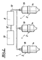
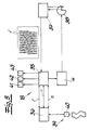
- the lubrication points are assigned by locally Lubricator 1 lubricated, the lubricator 1 arranged in the lubricator housing 2 Lubricant supply 3 and one in the lubricator housing have arranged electric motor drive 4 (Fig. 3).
- the operating status data of the machine to be lubricated and the operating status data of the lubricators a central computer 5 fed to a central control room 6.
- the lubricant dispenser becomes operating status data 1 controlled from the central control room 6.
- a laptop 7 for recording and evaluating the Operating status data and to control the lubricator be used.
- PLC system-programmed control
- the central control room 6 has a broadcasting station Receiving device 9.
- the embodiment 1 is by means of an arrow 10 has been indicated that the central control room or central computer to a control computer 11 of a control center, expediently over the internet.
- the control center with the host computer 11 preferably serves as Service center from which customer-specific operations can be planned and carried out.
- the central computer 5 is via a method Bus system 12 with the machine control of the lubrication Machine 13 and with control devices of the lubricators 1 connected.
- the lubricators 1 are also from from the central control room with external energy supply. She can, which is also indicated in Fig. 2, lubricant reservoir 14 different sizes and filled with different lubricants.
- Fig. 3 shows one in the context of the invention Process used lubricator 1 with lubricator housing 2 that from a lubricant reservoir 14 as the lower housing part and an upper housing part 15 exists.
- the electromotive is also shown Drive 4 with assigned output shaft.
- An actuating piston 16 is arranged in a rotationally fixed manner in the lubricant reservoir 14, gripped by a spindle 17 and by a Rotary movement of the spindle 17 is movable in the ejection direction.
- the upper housing part 15 can batteries 19 for Power supply included.
- the power supply of Lubricator is done from the outside. It is understood that the lubricator for use as part of the inventive method with not shown in Fig. 3 Facilities for communication with the Central control room or equipped with the central computer. To this extent, electrical lines, not shown, can the lubricator or connected to the circuit board his. The lubricator can also not shown receiving and transmitting devices for the wireless communication.
- the core of the central lubrication system is a central control unit 5, previously also referred to as the central computer, with a microcomputer 20 and a programmable logic controller Control 21.
- the central control unit 5 is in the Data exchange with the machine control 22 of the lubricating machine. Data communication is through Input signal lines 23 indicated.
- the central control unit 5 is also in data exchange with the control devices 18 of the lubricator 1, z. B. via a bus system 24.
- the central control unit 5 also has a power supply unit 25 preparation of the supply voltage for the lubricator 1, an input module 26 with inputs for sensors on the device to be lubricated, an interface 27 for download and maintenance, a control panel 28 with display, an output module 29 with outputs for the to the control devices 18 the lubricator 1 leading bus system and (optionally) has an interface 30 for remote maintenance.
- the central control device 5 is via output devices 31 for output signals with the control devices 18 of the lubricator 1 connected.
- the output devices 31 according to that shown in FIG. 4 Block diagram of a voltage conditioning 32 for the external energy supply of the lubricator 1, a level converter 33 and devices 34 for a Signal conditioning.
- the control device 18 is on a Inside the housing, preferably above the electromotive Drive arranged board housed and has a microcontroller as essential components 35, a data memory 36 and a motion sensor 37 for the direct or indirect recording of the Rotational movement of the output shaft.
- the Motion sensor 37 shown as a light barrier with one driven by the electric motor drive 4 Signal disk 38 interacts.
- the microcontroller 35 is via interfaces with the motion sensor 37 and the connected electromechanical drive 4 and is in Data exchange with the data store 36.
- the data store 36 retains its memory content regardless of the Power supply for the microcontroller 35.
- the memory content can be read and overwritten.
- the data storage 36 is also a switching device 39 with a reset switch 40 assigned to delete the data storage.
- the microcontroller 35 starts the electromotive Drive 4 based on one of the central control unit 5 emitted control pulse or in from the control device predetermined intervals.
- the number of from the motion sensor 37 signals are emitted by the microcontroller 35 counted and with a target number stored there compared. After reaching the specified number, the Motor 4 stopped.
- the microcontroller 35 adds the Measurement signals n of the motion sensor 37 continuously to one operating value stored in the data memory 36 and there the sum as a new operating value in the data memory 36 on. In the course of the data exchange, the elapsed Dispensing time t in the data memory 36 as the operating value stored.
- the electric motor drive 4 with an associated control device 18 is in the upper housing part 15 of the lubricator 1 arranged, which is detachable with a lubricant supply 3, the piston 16 and the spindle 17 containing Lubricant container 14 is connected.
- the Lubricant container 14 with piston 16 and spindle 17 is a disposable part.
- Selector switches are located on the input interfaces of the microcontroller for the donation time t and for the size V of the Lubricant container 14 connected. Using the selector switch for the dispensing time t, the intervals are between the lubrication pulses changeable. The information about the Size V of the lubricant container 14 can also in Data storage 36 are stored.
- a signal device 41 for displaying a necessary change of the lubricant container which responds when the sum of the emitted by the motion sensor 37 Signals n reached a default value.
- a signal device 42 for displaying an interference signal which responds when the frequency f of the Motion sensor 37 emitted signal sequence during the Operation of the electric motor drive 4 a predetermined Control value falls below or the time interval exceeds a limit between two signals.
- a signaling the operational readiness Function display 43 connected to the Engine operation and the break intervals with different optical signals There is not just one local display of the operating status of the lubricator, but the signals 41, 42, 43 described are sent via the data communication line 24 to the Central control unit 5 reported.
- the control devices 18 of the lubricator 1 are modular.
- the basic modules are the electromotive Drive 4 with an associated motion sensor for the indirect or direct detection of spindle revolutions, a circuit board with the microcontroller 35 and an interface module 44 for data communication with the central control unit 5.
- Im Further modules are provided for an exemplary embodiment internal power supply 45, for setting the Donation time 46, for signaling the operating status 47, a memory chip 48 with the data memory and one assigned switching device with reset function for the Deletion of the data memory and a device 49 for adjusting the size of the lubricant reservoir or if necessary for an automatic size detection.
Landscapes
- Engineering & Computer Science (AREA)
- General Engineering & Computer Science (AREA)
- Mechanical Engineering (AREA)
- Auxiliary Devices For Machine Tools (AREA)
- General Details Of Gearings (AREA)
- Lubricants (AREA)
- Organic Low-Molecular-Weight Compounds And Preparation Thereof (AREA)
Description
- Fig. 1 und 2
- das Schema des erfindungsgemäßen Verfahrens in verschiedenen Ausführungen,
- Fig. 3
- einen Schmierstoffgeber zum Einsatz im Rahmen des erfindungsgemäßen Verfahrens,
- Fig. 4
- das Blockschaltbild einer Zentralschmieranlage zur Durchführung des erfindungsgemäßen Verfahrens,
- Fig. 5
- das Blockschaltbild einer Steuerungseinrichtung der Schmierstoffgeber.
Claims (21)
- Verfahren zur Schmierung einer Vorrichtung mit mehreren Schmierstellen, wobei
den Schmierstellen durch zugeordnete Schmierstoffgeber, die jeweils einen elektromotorischen Antrieb mit Steuereinrichtung, einen Schmierstoffbehälter mit Schmierstoffvorrat, eine mit dem Antrieb verbundene Spindel sowie einen von der Spindel bewegbaren Kolben aufweisen, Schmierstoff zugeführt wird,
die Schmierstoffabgabe jedes Schmierstoffgebers in einer zeitlichen Abfolge von Spendeintervallen erfolgt und die Spendezeitpunkte für die Schmierstoffabgabe sowie die Dauer der Spendeintervalle gesteuert werden,
die Steuereinrichtungen der Schmierstoffgeber von einem Zentralrechner in Abhängigkeit von Betriebszustandsdaten der geschmierten Vorrichtung angesteuert werden und
die Versorgungsspannung der Steuereinrichtungen in Abhängigkeit des Betriebszustandes der zu schmierenden Vorrichtung ein- und ausgeschaltet wird, wobei die Spendezeit, in der die Schmierstoffspender betriebsbereit sind, von den Steuereinrichtungen der Schmierstoffgeber fortlaufend erfasst und permanent abgespeichert wird und wobei die Steuereinrichtungen eine Schmierstoffabgabe der Schmierstoffgeber auslösen, wenn die Spendezeit einen von der Steuereinrichtung vorgegebenen Spendezeitpunkt erreicht. - Verfahren nach Anspruch 1, wobei Betriebszustandsdaten der Schmierstoffgeber von den Steuereinrichtungen erfasst und dem Zentralrechner zugeführt werden.
- Verfahren nach Anspruch 1 oder 2, wobei die Anzahl der Spindelumdrehungen mittelbar oder unmittelbar durch einen Bewegungssensor erfasst wird und wobei der elektromotorische Antrieb der Schmierstoffgeber aufgrund eines von dem Zentralrechner abgegebenen Steuerimpulses oder in von der Steuereinrichtung vorgegebenen Intervallen in Betrieb gesetzt sowie nach einer vorgegebenen Anzahl der von dem Bewegungssensor detektierten Umdrehungen gestoppt wird.
- Verfahren nach Anspruch 3, wobei die Summe aller Spindelumdrehungen in einem Datenspeicher der Steuereinrichtung permanent abgespeichert wird und dem Zentralrechner ein Signal zur Leerstandsanzeige zugeführt wird, wenn eine vorgegebene Anzahl von Spindelumdrehungen erreicht wird.
- Verfahren nach Anspruch 1 oder 2, wobei die Spendezeitpunkte für die Schmierstoffabgabe sowie die Dauer der Spenderintervalle von dem Zentralrechner gesteuert werden.
- Verfahren nach einem der Ansprüche 1 bis 5, wobei mit einer drahtlosen Signalübertragung zwischen dem Zentralrechner und den Schmierstoffgebern gearbeitet wird.
- Zentralschmieranlage für die Schmierung einer Vorrichtung mit mehreren Schmierstellen, bestehend aus
einer zentralen Steuereinheit (5) mit einem Mikrocomputer (20) und einer speicherprogrammierbaren Steuerung (21) und
Schmierstoffgebern (1), die jeweils einen elektromotorischen Antrieb (4) mit zugeordneter Steuereinrichtung (18), einen Schmierstoffbehälter (14) mit Schmierstoffvorrat (3), eine mit dem Antrieb (4) verbundene Spindel (17) sowie einen von der Spindel (17) bewegbaren Kolben (16) aufweisen,
wobei die zentrale Steuereinheit (5) Eingangssignalleitungen (23) für Betriebszustandssignale der Vorrichtung aufweist und über Ausgabevorrichtungen (31) für Ausgangssignale mit den Steuereinrichtungen (18) der Schmierstoffgeber (1) verbunden sind
und wobei die Steuereinrichtung (18) der Schmierstoffgeber einen Microcontroller (35) sowie einen Datenspeicher (36), der seinen Speicherinhalt unabhängig von der Stromversorgung des Microcontrollers (35) behält und dessen Speicherinhalt les- und überschreibbar ist, aufweist, wobei im Zuge eines zwischen dem Microcontroller (35) und dem Datenspeicher (36) eingerichteten Datenaustauschs die verstrichene Spendezeit im Datenspeicher (36) als Betriebswerte abspeicherbar sind. - Zentralschmieranlage nach Anspruch 7, dadurch gekennzeichnet, dass die Steuereinrichtung (18) der Schmierstoffgeber (1) einen Bewegungssensor (37) zur mittelbaren oder unmittelbaren Erfassung der Anzahl der Spindelumdrehungen aufweist und den elektromotorischen Antrieb (4) aufgrund eines von der zentralen Steuereinheit 5) abgegebenen Steuerimpulses oder in von der Steuereinrichtung (18) vorgegebenen Intervallen startet sowie nach einer vorgegebenen Anzahl der von dem Bewegungssensor (37) detektierten Umdrehungen den elektromotorischen Antrieb (4) stoppt.
- Zentralschmieranlage nach Anspruch 7 oder 8, dadurch gekennzeichnet, dass die Summe der von dem Bewegungssensor (37) detektierten Umdrehungen im Datenspeicher (36) als Betriebswerte abspeicherbar sind.
- Zentralschmieranlage nach einem der Ansprüche 7 bis 9, dadurch gekennzeichnet, dass dem Datenspeicher (36) eine Schalteinrichtung (39) mit einem Reset-Schalter (40) zur Löschung des Speicherinhalts zugeordnet ist.
- Zentralschmieranlage nach Anspruch 10, dadurch gekennzeichnet, dass die elektromotorischen Antriebe (4) mit den zugeordneten Steuereinrichtungen (18) in einem Gehäuseoberteil (15) der Schmierstoffgeber (1) angeordnet sind, welches lösbar mit einem den Schmierstoffvorrat (3), den Kolben (16) und die Spindel (17) enthaltenden Schmierstoffbehälter (14) verbunden ist, dass der Reset-Schalter (40) beim Anschluss eines fabrikneuen, noch den gesamten Schmierstoffvorrat (3) enthaltenden Schmierstoffbehälters (14) mit dem Kolben (16) wechselwirkt und die Löschung des Speicherinhalts auslöst.
- Zentralschmieranlage nach einem der Ansprüche 7 bis 11, dadurch gekennzeichnet, dass die Ausgabevorrichtungen (31) eine Spannungsaufbereitung (32) für die externe Energieversorgung der Schmierstoffgeber (1) und einen Pegelwandler (33) aufweisen.
- Zentralschmieranlage nach einem der Ansprüche 7 bis 12, dadurch gekennzeichnet, dass die zentrale Steuereinheit (5) Eingänge (26) für Sensoren an der zu schmierenden Vorrichtung und Schnittstellen (27, 28, 29) für Download und Peripherie-Geräte, insbesondere Bedien- und Anzeigegeräte, aufweist.
- Zentralschmieranlage nach einem der Ansprüche 7 bis 13, dadurch gekennzeichnet, dass die zentrale Steuereinheit (5) über ein Bussystem (24) mit den Steuereinrichtungen (18) der Schmierstoffgeber (4) verbunden ist.
- Zentralschmieranlage nach einem der Ansprüche 7 bis 14, dadurch gekennzeichnet, dass die Schmierstoffgeber (1) einen Wahlschalter für die Einstellung der Spendeintervalle aufweisen.
- Zentralschmieranlage nach einem der Ansprüche 7 bis 15, dadurch gekennzeichnet, dass die Schmierstoffgeber (1) einen Wahlschalter für die Einstellung der Größe des Schmierstoffbehälters aufweisen.
- Zentralschmieranlage nach einem der Ansprüche 7 bis 16, dadurch gekennzeichnet, dass die Steuereinrichtungen (18) der Schmierstoffgeber (1) eine Vorrichtung zur automatischen Erkennung der Schmierstoffbehältergröße aufweisen.
- Zentralschmieranlage nach einem der Ansprüche 7 bis 17, dadurch gekennzeichnet, dass die Schmierstoffgeber (1) eine Signaleinrichtung (41) zur Anzeige eines erforderlichen Wechsels des Schmierstoffbehälters aufweisen, welche anspricht, wenn die Summe der vom Bewegungssensor (37) abgegebenen Signale einen Vorgabewert erreicht.
- Zentralschmieranlage nach einem der Ansprüche 7 bis 18, dadurch gekennzeichnet, dass die Schmierstoffgeber (1) eine Signaleinrichtung (42) zur Anzeige eines Störsignals aufweisen, die anspricht, wenn die Frequenz der vom Bewegungssensor (37) abgegebenen Signalfolge während des Betriebs des elektromotorischen Antriebs (4) einen vorgegebenen Kontrollwert unterschreitet oder die Stromaufnahme des elektromotorischen Antriebs einen Grenzwert überschreitet.
- Zentralschmieranlage nach einem der Ansprüche 7 bis 19, dadurch gekennzeichnet, dass die Schmierstoffgeber (1) eine die Betriebsbereitschaft signalisierende Funktionsanzeige (43) aufweisen, die den Motorbetrieb und die Pausenintervalle mit unterschiedlichen optischen Signalen anzeigt.
- Zentralschmieranlage nach einem der Ansprüche 7 bis 20, dadurch gekennzeichnet, dass die Schmierstoffgeber (1) und die zentrale Steuereinheit (5) Sende/Empfangseinrichtungen für eine drahtlose Signalübertragung aufweisen.
Priority Applications (4)
| Application Number | Priority Date | Filing Date | Title |
|---|---|---|---|
| JP10363343A JPH11287395A (ja) | 1997-12-23 | 1998-12-21 | 潤滑個所が多数ある装置に潤滑油を注す方法およびこの方法を実施する中央潤滑設備 |
| US09/218,410 US6125969A (en) | 1997-12-23 | 1998-12-22 | Method of and apparatus for lubricating an apparatus having a number of lubricant locations |
| CA002256150A CA2256150A1 (en) | 1997-12-23 | 1998-12-22 | Method of and apparatus for lubricating an apparatus having a number of lubricant locations |
| AU98169/98A AU739188B2 (en) | 1997-12-23 | 1998-12-23 | Method to lubricate a device with several lubrication points and a central lubricating equipment to carry out the method |
Applications Claiming Priority (2)
| Application Number | Priority Date | Filing Date | Title |
|---|---|---|---|
| DE19757546 | 1997-12-23 | ||
| DE19757546A DE19757546A1 (de) | 1997-12-23 | 1997-12-23 | Verfahren zur zentralen Steuerung und/oder Regelung der Schmierung zumindest einer Maschine |
Publications (2)
| Publication Number | Publication Date |
|---|---|
| EP0926426A1 EP0926426A1 (de) | 1999-06-30 |
| EP0926426B1 true EP0926426B1 (de) | 2003-04-02 |
Family
ID=7853193
Family Applications (1)
| Application Number | Title | Priority Date | Filing Date |
|---|---|---|---|
| EP98119208A Expired - Lifetime EP0926426B1 (de) | 1997-12-23 | 1998-10-12 | Verfahren zur Schmierung einer Vorrichtung mit mehreren Schmierstellen und Zentralschmieranlage zur Durchführung des Verfahrens |
Country Status (5)
| Country | Link |
|---|---|
| EP (1) | EP0926426B1 (de) |
| AT (1) | ATE236375T1 (de) |
| DE (2) | DE19757546A1 (de) |
| ES (1) | ES2193460T3 (de) |
| PT (1) | PT926426E (de) |
Cited By (1)
| Publication number | Priority date | Publication date | Assignee | Title |
|---|---|---|---|---|
| DE102007033539A1 (de) | 2007-07-19 | 2009-01-22 | Perma-Tec Gmbh & Co. Kg | Verfahren zur Schmierung mehrerer Schmierstellen |
Families Citing this family (14)
| Publication number | Priority date | Publication date | Assignee | Title |
|---|---|---|---|---|
| DE29818084U1 (de) * | 1998-10-12 | 1999-01-28 | Satzinger Gmbh & Co, 97717 Euerdorf | Schmierstoffspender |
| DE19857289C1 (de) * | 1998-12-13 | 2000-05-04 | Brueckner Maschbau | Verfahren zur Schmierung von Transportsystemen oder Teilen davon sowie Verwendung einer Schmiermittelvorrichtung zur Durchführung des Verfahrens und ein zugehöriges Transportsystem mit entsprechender Schmiermitteleinrichtung |
| SE512648C2 (sv) | 1999-07-02 | 2000-04-17 | Assalub Ab | Metod och anordning för manuell smörjning av ett flertal smörjpunkter |
| US6993298B2 (en) * | 2001-09-07 | 2006-01-31 | Siemens Energy & Automation, Inc. | Programmable controller with RF wireless interface |
| DE102004039719A1 (de) * | 2004-08-17 | 2006-02-23 | Adam Opel Ag | Zeigerinstrument für ein Kraftfahrzeug |
| CA135884S (en) | 2010-06-10 | 2011-01-10 | A T S Electro Lube Holdings Ltd | Dual cartridge lubricator |
| US8936135B2 (en) | 2010-11-29 | 2015-01-20 | Lincoln Industrial Corporation | Pump having heated reservoir |
| EP2751467A4 (de) | 2011-08-30 | 2015-05-13 | Stephania Holdings Inc | Verfahren zur steuerung einer schmiervorrichtung, kommunikationsverfahren sowie vorrichtungen und systeme dafür |
| BE1020552A5 (fr) * | 2012-03-13 | 2013-12-03 | Cockerill Maintenance & Ingenierie Sa | Dispositif et methode de controle et de validation du graissage manuel. |
| EP2841841B1 (de) | 2012-04-27 | 2020-07-29 | Igralub North America, LLC | System und verfahren für flottenradschienenschmierung und lärmmanagement |
| DE102017125307B4 (de) * | 2017-10-27 | 2025-12-24 | Groeneveld-Beka Gmbh | Zentralschmieranlage und System |
| DE102017126385A1 (de) * | 2017-11-10 | 2019-05-16 | Eugen Woerner Gmbh & Co. Kg Zentralschmieranlagen | Schmieranlage mit einem Kommunikationsnetz zwischen einem Hauptgerät und mindestens einem Anbaugerät |
| DE102023105820B3 (de) | 2023-03-09 | 2024-05-29 | Perma-Tec Gmbh & Co. Kg | Verfahren zur Bestimmung und/oder Überwachung des Zustandes eines Schmierstoffspenders |
| CA221424S (en) | 2023-05-12 | 2024-08-13 | A T S Electro Lube Int Inc | Lubricant applicator |
Family Cites Families (8)
| Publication number | Priority date | Publication date | Assignee | Title |
|---|---|---|---|---|
| US4368803A (en) * | 1980-08-07 | 1983-01-18 | Madison-Kipp Corporation | Apparatus for dispensing fluid onto a moving mechanical system |
| JP2765897B2 (ja) * | 1988-12-23 | 1998-06-18 | 株式会社日立製作所 | 潤滑剤供給方法およびその方法を用いた軸受装置 |
| CA2057125C (en) * | 1990-12-06 | 1998-05-05 | David C. Beck | Apparatus for controlling and monitoring a lubricating system |
| IT1245144B (it) * | 1991-02-08 | 1994-09-13 | Dropsa Spa | Impianto per la distribuzione di lubrificazione a piu' utenze con distributori connessi ad una stessa linea di mandata o distribuzione del lubrificante e controllati a distanza |
| GB2271391B (en) * | 1992-10-12 | 1995-08-02 | Hornche Trading Co Ltd | Automatic grease dispenser |
| US5711615A (en) * | 1993-03-18 | 1998-01-27 | Barmag Ag | Antifriction bearing |
| US5732794A (en) * | 1994-09-30 | 1998-03-31 | Orlitzky; Anton T. | Auger-driven automatic lubricator |
| DE29715808U1 (de) * | 1997-09-03 | 1997-11-06 | Satzinger Gmbh & Co, 97717 Euerdorf | Schmierstoffspender |
-
1997
- 1997-12-23 DE DE19757546A patent/DE19757546A1/de not_active Withdrawn
-
1998
- 1998-10-12 ES ES98119208T patent/ES2193460T3/es not_active Expired - Lifetime
- 1998-10-12 PT PT98119208T patent/PT926426E/pt unknown
- 1998-10-12 DE DE59807731T patent/DE59807731D1/de not_active Expired - Lifetime
- 1998-10-12 AT AT98119208T patent/ATE236375T1/de not_active IP Right Cessation
- 1998-10-12 EP EP98119208A patent/EP0926426B1/de not_active Expired - Lifetime
Cited By (1)
| Publication number | Priority date | Publication date | Assignee | Title |
|---|---|---|---|---|
| DE102007033539A1 (de) | 2007-07-19 | 2009-01-22 | Perma-Tec Gmbh & Co. Kg | Verfahren zur Schmierung mehrerer Schmierstellen |
Also Published As
| Publication number | Publication date |
|---|---|
| EP0926426A1 (de) | 1999-06-30 |
| ATE236375T1 (de) | 2003-04-15 |
| PT926426E (pt) | 2003-08-29 |
| ES2193460T3 (es) | 2003-11-01 |
| DE19757546A1 (de) | 1999-07-01 |
| DE59807731D1 (de) | 2003-05-08 |
Similar Documents
| Publication | Publication Date | Title |
|---|---|---|
| EP0994289B1 (de) | Schmierstoffspender | |
| EP0926426A1 (de) | Verfahren zur Schmierung einer Vorrichtung mit mehreren Schmierstellen und Zentralschmieranlage zur Durchführung des Verfahrens | |
| DE4422407C2 (de) | Schmierstoffspender | |
| EP2966299B1 (de) | Dosierpumpe, sendeeinheit und verfahren | |
| DE102017200481B4 (de) | Verfahren zu einem Betrieb eines Schmierstoffverteilsystem | |
| EP1135645B1 (de) | Vorrichtung zur schmierung eines wälzlagers | |
| US6125969A (en) | Method of and apparatus for lubricating an apparatus having a number of lubricant locations | |
| EP0982528A1 (de) | Schmierstoffgeber | |
| EP0211212A2 (de) | Verfahren und Vorrichtung zur Ermittlung und Auswertung von Maschinenzustandsdaten | |
| DE102017103020B4 (de) | Gebäudetürsystem für zumindest einen elektromotorisch angetriebenen Türflügel einer Tür und Verfahren zum Erzeugen von Wartungsinformationen für ein Gebäudetürsystem | |
| DE102005016855A1 (de) | Schnittstellenmodul zur Anordnung in oder an einem Motor | |
| EP3438517A1 (de) | Schmiersystem mit einem signalübertragungselement | |
| DE2823558C2 (de) | Vorrichtung zum Überwachen komplexer Arbeitsmaschinen, wie Kompressoranlagen | |
| DE102017109403A1 (de) | Verfahren und Vorrichtung zur Absolutpositionsbestimmung eines sich um eine Drehachse drehenden Bauteiles eines Aktors, insbesondere eines Kupplungsaktors | |
| EP0102080B2 (de) | Vorrichtung zur Füllmengeneinstellung von Schmierölen in Antriebsaggregaten | |
| DE102007033539A1 (de) | Verfahren zur Schmierung mehrerer Schmierstellen | |
| EP0749934A2 (de) | Verfahren und Vorrichtung zur Ermittlung der dynamischen Beanspruchung an Bauteilen, Anlagen und Maschinen | |
| DE3630327A1 (de) | Zentralschmieranlage fuer fahrzeuge | |
| EP0026869B1 (de) | Wartungs-Überwachungseinrichtung für eine Anlage | |
| DE3150313C2 (de) | Anordnung zur Ermittlung und Rückmeldung der Stellung einer Reihe von Schaltern und zur Überwachung der Verbindungsleitung | |
| EP1881204A1 (de) | Zylinderservicemodul | |
| DE3832258A1 (de) | Verfahren und anordnung zum erzeugen von steuerimpulsen fuer schrittmotoren | |
| DE10059797A1 (de) | Anordnung aus mehreren, in einem Netzwerk arbeitenden Schmierstoffgebern | |
| WO1981003233A1 (fr) | Dispositif de commande | |
| DE102016123117A1 (de) | Kompaktes Zentralschmiersystem mit Kartuschenaufnahme- und Verteilereinheit |
Legal Events
| Date | Code | Title | Description |
|---|---|---|---|
| PUAI | Public reference made under article 153(3) epc to a published international application that has entered the european phase |
Free format text: ORIGINAL CODE: 0009012 |
|
| AK | Designated contracting states |
Kind code of ref document: A1 Designated state(s): AT BE CH CY DE DK ES FI FR GB GR IE IT LI LU MC NL PT SE |
|
| AX | Request for extension of the european patent |
Free format text: AL;LT;LV;MK;RO;SI |
|
| RAP1 | Party data changed (applicant data changed or rights of an application transferred) |
Owner name: PERMA-TEC GMBH & CO. KG |
|
| 17P | Request for examination filed |
Effective date: 19990709 |
|
| AKX | Designation fees paid |
Free format text: AT BE CH CY DE DK ES FI FR GB GR IE IT LI LU MC NL PT SE |
|
| GRAH | Despatch of communication of intention to grant a patent |
Free format text: ORIGINAL CODE: EPIDOS IGRA |
|
| GRAH | Despatch of communication of intention to grant a patent |
Free format text: ORIGINAL CODE: EPIDOS IGRA |
|
| GRAA | (expected) grant |
Free format text: ORIGINAL CODE: 0009210 |
|
| AK | Designated contracting states |
Designated state(s): AT BE CH CY DE DK ES FI FR GB GR IE IT LI LU MC NL PT SE |
|
| PG25 | Lapsed in a contracting state [announced via postgrant information from national office to epo] |
Ref country code: NL Free format text: LAPSE BECAUSE OF FAILURE TO SUBMIT A TRANSLATION OF THE DESCRIPTION OR TO PAY THE FEE WITHIN THE PRESCRIBED TIME-LIMIT Effective date: 20030402 Ref country code: IE Free format text: LAPSE BECAUSE OF NON-PAYMENT OF DUE FEES Effective date: 20030402 |
|
| REG | Reference to a national code |
Ref country code: GB Ref legal event code: FG4D Free format text: NOT ENGLISH |
|
| REG | Reference to a national code |
Ref country code: CH Ref legal event code: EP |
|
| REG | Reference to a national code |
Ref country code: IE Ref legal event code: FG4D Free format text: GERMAN |
|
| REF | Corresponds to: |
Ref document number: 59807731 Country of ref document: DE Date of ref document: 20030508 Kind code of ref document: P |
|
| GBT | Gb: translation of ep patent filed (gb section 77(6)(a)/1977) |
Effective date: 20030520 |
|
| PG25 | Lapsed in a contracting state [announced via postgrant information from national office to epo] |
Ref country code: SE Free format text: LAPSE BECAUSE OF FAILURE TO SUBMIT A TRANSLATION OF THE DESCRIPTION OR TO PAY THE FEE WITHIN THE PRESCRIBED TIME-LIMIT Effective date: 20030702 Ref country code: GR Free format text: LAPSE BECAUSE OF FAILURE TO SUBMIT A TRANSLATION OF THE DESCRIPTION OR TO PAY THE FEE WITHIN THE PRESCRIBED TIME-LIMIT Effective date: 20030702 Ref country code: DK Free format text: LAPSE BECAUSE OF FAILURE TO SUBMIT A TRANSLATION OF THE DESCRIPTION OR TO PAY THE FEE WITHIN THE PRESCRIBED TIME-LIMIT Effective date: 20030702 |
|
| NLV1 | Nl: lapsed or annulled due to failure to fulfill the requirements of art. 29p and 29m of the patents act | ||
| PG25 | Lapsed in a contracting state [announced via postgrant information from national office to epo] |
Ref country code: LU Free format text: LAPSE BECAUSE OF NON-PAYMENT OF DUE FEES Effective date: 20031012 Ref country code: CY Free format text: LAPSE BECAUSE OF FAILURE TO SUBMIT A TRANSLATION OF THE DESCRIPTION OR TO PAY THE FEE WITHIN THE PRESCRIBED TIME-LIMIT Effective date: 20031012 Ref country code: AT Free format text: LAPSE BECAUSE OF NON-PAYMENT OF DUE FEES Effective date: 20031012 |
|
| PG25 | Lapsed in a contracting state [announced via postgrant information from national office to epo] |
Ref country code: MC Free format text: LAPSE BECAUSE OF NON-PAYMENT OF DUE FEES Effective date: 20031031 Ref country code: LI Free format text: LAPSE BECAUSE OF NON-PAYMENT OF DUE FEES Effective date: 20031031 Ref country code: CH Free format text: LAPSE BECAUSE OF NON-PAYMENT OF DUE FEES Effective date: 20031031 Ref country code: BE Free format text: LAPSE BECAUSE OF NON-PAYMENT OF DUE FEES Effective date: 20031031 |
|
| REG | Reference to a national code |
Ref country code: ES Ref legal event code: FG2A Ref document number: 2193460 Country of ref document: ES Kind code of ref document: T3 |
|
| REG | Reference to a national code |
Ref country code: IE Ref legal event code: FD4D Ref document number: 0926426E Country of ref document: IE |
|
| ET | Fr: translation filed | ||
| PLBE | No opposition filed within time limit |
Free format text: ORIGINAL CODE: 0009261 |
|
| STAA | Information on the status of an ep patent application or granted ep patent |
Free format text: STATUS: NO OPPOSITION FILED WITHIN TIME LIMIT |
|
| 26N | No opposition filed |
Effective date: 20040105 |
|
| BERE | Be: lapsed |
Owner name: *PERMA-TEC G.M.B.H. & CO. K.G. Effective date: 20031031 |
|
| REG | Reference to a national code |
Ref country code: CH Ref legal event code: PL |
|
| PGFP | Annual fee paid to national office [announced via postgrant information from national office to epo] |
Ref country code: PT Payment date: 20040920 Year of fee payment: 7 |
|
| PGFP | Annual fee paid to national office [announced via postgrant information from national office to epo] |
Ref country code: FI Payment date: 20041012 Year of fee payment: 7 |
|
| PG25 | Lapsed in a contracting state [announced via postgrant information from national office to epo] |
Ref country code: FI Free format text: LAPSE BECAUSE OF NON-PAYMENT OF DUE FEES Effective date: 20051012 |
|
| PG25 | Lapsed in a contracting state [announced via postgrant information from national office to epo] |
Ref country code: PT Free format text: LAPSE BECAUSE OF NON-PAYMENT OF DUE FEES Effective date: 20060412 |
|
| REG | Reference to a national code |
Ref country code: PT Ref legal event code: MM4A Effective date: 20060412 |
|
| PGFP | Annual fee paid to national office [announced via postgrant information from national office to epo] |
Ref country code: ES Payment date: 20081027 Year of fee payment: 11 |
|
| PGFP | Annual fee paid to national office [announced via postgrant information from national office to epo] |
Ref country code: IT Payment date: 20081025 Year of fee payment: 11 |
|
| PGFP | Annual fee paid to national office [announced via postgrant information from national office to epo] |
Ref country code: GB Payment date: 20081021 Year of fee payment: 11 |
|
| PG25 | Lapsed in a contracting state [announced via postgrant information from national office to epo] |
Ref country code: GB Free format text: LAPSE BECAUSE OF NON-PAYMENT OF DUE FEES Effective date: 20091012 |
|
| PG25 | Lapsed in a contracting state [announced via postgrant information from national office to epo] |
Ref country code: IT Free format text: LAPSE BECAUSE OF NON-PAYMENT OF DUE FEES Effective date: 20091012 |
|
| REG | Reference to a national code |
Ref country code: ES Ref legal event code: FD2A Effective date: 20110408 |
|
| PG25 | Lapsed in a contracting state [announced via postgrant information from national office to epo] |
Ref country code: ES Free format text: LAPSE BECAUSE OF NON-PAYMENT OF DUE FEES Effective date: 20110324 |
|
| PG25 | Lapsed in a contracting state [announced via postgrant information from national office to epo] |
Ref country code: ES Free format text: LAPSE BECAUSE OF NON-PAYMENT OF DUE FEES Effective date: 20091013 |
|
| PGFP | Annual fee paid to national office [announced via postgrant information from national office to epo] |
Ref country code: FR Payment date: 20121031 Year of fee payment: 15 |
|
| REG | Reference to a national code |
Ref country code: FR Ref legal event code: ST Effective date: 20140630 |
|
| PG25 | Lapsed in a contracting state [announced via postgrant information from national office to epo] |
Ref country code: FR Free format text: LAPSE BECAUSE OF NON-PAYMENT OF DUE FEES Effective date: 20131031 |
|
| PGFP | Annual fee paid to national office [announced via postgrant information from national office to epo] |
Ref country code: DE Payment date: 20170928 Year of fee payment: 20 |
|
| REG | Reference to a national code |
Ref country code: DE Ref legal event code: R071 Ref document number: 59807731 Country of ref document: DE |