EP0926345A2 - Shape of suction hole and discharge hole of refrigerant compressor - Google Patents
Shape of suction hole and discharge hole of refrigerant compressor Download PDFInfo
- Publication number
- EP0926345A2 EP0926345A2 EP98124026A EP98124026A EP0926345A2 EP 0926345 A2 EP0926345 A2 EP 0926345A2 EP 98124026 A EP98124026 A EP 98124026A EP 98124026 A EP98124026 A EP 98124026A EP 0926345 A2 EP0926345 A2 EP 0926345A2
- Authority
- EP
- European Patent Office
- Prior art keywords
- suction
- discharge
- valve plate
- valve
- piston cylinder
- Prior art date
- Legal status (The legal status is an assumption and is not a legal conclusion. Google has not performed a legal analysis and makes no representation as to the accuracy of the status listed.)
- Granted
Links
Images


Classifications
-
- F—MECHANICAL ENGINEERING; LIGHTING; HEATING; WEAPONS; BLASTING
- F04—POSITIVE - DISPLACEMENT MACHINES FOR LIQUIDS; PUMPS FOR LIQUIDS OR ELASTIC FLUIDS
- F04B—POSITIVE-DISPLACEMENT MACHINES FOR LIQUIDS; PUMPS
- F04B39/00—Component parts, details, or accessories, of pumps or pumping systems specially adapted for elastic fluids, not otherwise provided for in, or of interest apart from, groups F04B25/00 - F04B37/00
- F04B39/10—Adaptations or arrangements of distribution members
- F04B39/1073—Adaptations or arrangements of distribution members the members being reed valves
- F04B39/108—Adaptations or arrangements of distribution members the members being reed valves circular reed valves
Definitions
- the present invention relates to a refrigerant compressor used for an automotive air-conditioning system. More particularly, the present invention relates to shapes of suction holes and discharge holes provided in a valve plate of a compressor.
- Compressor 100 comprises front housing 30, housing 27, valve plate 1, and rear housing 32.
- a drive shaft 34 which is supported rotatably by needle bearings 35 and 36.
- cam rotor 37 which is fixed to drive shaft 34 engages the inner wall of front housing 30 via thrust bearing 38.
- Cam rotor 37 rotates when drive shaft 34 is rotated.
- Hinge mechanism 39 couples cam rotor 37 with inclined plate 40.
- Inclined plate 40 rotates with cam rotor 37.
- Wobble plate 43 engages with inclined plate 40 via thrust bearing 41 and needle bearing 42.
- a wobbling motion is induced in inclined plate 40, so that inclined plate 40 wobbles while rotating.
- This motion of inclined plate 40 transfers to wobble plate 43.
- Rotation of wobble plate 43 is inhibited by engagement with a guide bar 44. Therefore, only the wobbling component of the motion of inclined plate 40 is transferred from inclined plate 40 to wobble plate 43.
- Wobble plate 43 has a wobbling motion, but does not rotate with drive shaft 34.
- Rod 45 is connected by spherical coupling to wobble plate 43 and to a plurality of pistons 46. When wobble plate 43 wobbles, each of pistons 46 reciprocates in one of a plurality of cylinders 71.
- Suction valve reed 22, discharge valve reed 2, and valve retainer 3 are fixed by bolt 47 to valve plate 1.
- Suction holes 5 and discharge holes 4 correspond to each piston cylinder 71.
- Suction chamber 72 and discharge chamber 70 are formed by valve plate 1 and the rear housing 32; and are separated by inside partition plate 33.
- each piston 46 reciprocates in its respective piston cylinder 71.
- the suction phase is executed, and when piston 46 is moving rightward, the compression phase is executed.
- suction phase refrigerant gas in suction chamber 72 is drawn into piston cylinder 71 through suction hole 5. Due to the pressure variance between suction chamber 72 and piston cylinder 71, the refrigerant gas in suction chamber 72 flows to suction hole 5, passes through suctation hole 5, opens suction valve reed 22, and enters piston cylinder 71. Suction valve reed 22 prohibits a reverse flow of refrigerant gas into suction chamber 72 during the compression phase.
- the refrigerant gas in piston cylinder 71 is discharged into discharge chamber 70 through discharge hole 4. Due to the pressure variance between piston under 71 and discharge chamber 70, the refrigerant gas passes, through discharge hole 4, opens discharge valve reed 2, and enters discharge chamber 70. Discharge valve reed 2 prohibits a reverse flow of the refrigerant gas into piston cylinder 71 during the suction phase.
- Fig. 2a depicts a cross-sectional view of valve plate 1 from the rear housing side of valve plate 1.
- Fig. 2b depicts a cross-sectional view of valve plate 1 from the cylinder head side of valve plate 1.
- rear housing 32 is fixed to housing 27 by a plurality of bolts 130.
- Suction holes 5 and discharge holes 4 are disposed equiangularly around the center CO and correspond to piston cylinders 71.
- Suction chamber 72 and discharge chamber 70 are separated by inside partition plate 33.
- Discharge valve reed 2 within inside partition plate 33 is substantially star-shaped.
- the arms of discharge valve reed 2 cover discharge holes 4.
- suction valve reed 22 also is substantially star-shaped. Within each arm, a hole 22h enables the discharge gas to flow therethrough.
- Fig. 3 depicts valve plate 1 as viewed from the side of valve plate 1 facing discharge chamber 70.
- Discharge holes 4 and suction holes 5 are disposed equiangularly with respect to the center C of valve plate 1.
- Fig. 4 and Fig. 5 are corresponding radial, cross-sectional views of valve plate 1 of Fig. 1.
- Valve reed 2 is fixed between valve plate 1 and valve retainer 3.
- Discharge holes 4 have side walls which are substantially perpendicular to the opposing surfaces of valve plate 1.
- Fig. 4 and Fig. 5 depict valve plate 1 during the compression phase.
- the refrigerant gas When the refrigerant gas is discharged from cylinders 71, it strikes, pushes, and displaces valve reed 2.
- the refrigerant gas flows into discharge chamber 70 through a gap created between valve reed 2 and valve plate 1.
- refrigerant gas flow impinges against reed valve 2 in Fig. 4 its flow path may be diverted at an angle substantially perpendicular to valve plate 1. Turbulence in the refrigerant gas flow may be created due to the abrupt change in the direction of flow. Further, a portion of the refrigerant gas flow impinging against valve reed 2 may not enter discharge chamber 70, and may instead return to piston cylinder 71.
- turbulence of the refrigerant gas flow may result in flow resistance at discharge hole 4.
- Such flow resistance lowers the volumetric efficiency, a primary measure of the performance of compressor 100.
- the turbulence of flow also disturbs the motion of valve reed 2 and impedes valve reed 2 from discretely and completely opening and closing.
- the turbulence of flow in discharge holes 4 may cause noise in compressor 100. Similar problems may occur with respect to suction holes 5.
- a compressor according to the present invention is equipped with a valve plate that has suction passages and discharge passages.
- each of the discharge passages includes a first piston cylinder-side opening having an area, a discharge chamber-side opening having an area, and a sidewall extending between the openings. At least a portion of the discharge passage sidewall is tapered. The discharge chamber-side opening area is greater than the piston cylinder-side opening area.
- each of the suction passages includes a second piston cylinder-side opening having an area, a suction chamber-side opening having an area, and a sidewall extending between the openings. At least a portion of the suction passage sidewall is tapered.
- the piston cylinder-side opening area is greater than the suction chamber-side opening area.
- the sidewalls of the passages may include a substantially cylindrical portion. Further, the tapered portion of the sidewalls of the passages may be less than the thickness of the valve plate. Even with partial tapering, the objects of the present invention may be achieved.
- the flow path of the refrigerant gas may bend gradually.
- the flow path of the refrigerant gas does not strike the valve reed perpendicularly, but instead flows along the tapered portion of the sidewall.
- any turbulence of the refrigerant is reduced in the suction holes or discharge holes, so that the volumetric efficiency of the compressor may be improved and associated noise suppressed.
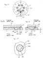
- FIG. 6 a plan view of a valve plate 11 from discharge chamber 70 in accordance to an embodiment of the present invention is depicted.
- Discharge holes 14 and suction holes 15 are disposed equiangularly in valve plate 11 with respect to center C.
- Figs. 7 and 8 are cross-sectional views of the discharge mechanism during a compression phase.
- Valve reed 12 is fixed between valve plate 11 and valve retainer 13.
- a sidewall 16 of discharge hole 14 is formed as a convex tapered surface. Small circular opening 16a is on the piston cylinder end of sidewall 16. Large circular opening 16b is on the discharge chamber end of sidewall 16.
- hole area Sa is defined by small circular opening 16a
- hole area Sb is defined by large circular opening 16b.
- area Sb is about 1.5 times greater than area Sa.
- the curve of sidewall 16 allows area Sa on the piston cylinder-side surface of valve plate 11 to increase gradually to area Sb on the discharge chamber-side surface of valve plate 11.
- a viscous fluid that flows near a wall of a chamber, or tube, flows along the surface.
- the refrigerant gas flows along sidewall 16 when discharge hole 14 is open, as indicated by the arrows in Fig. 7 and Fig. 8.
- the direction of flow of the refrigerant gas gradually bends in a lateral direction according to Figs. 7 and 8.
- the refrigerant gas is prevented from colliding directly upon valve reed 12. As a result, turbulence of the refrigerant gas within discharge hole 14 is reduced. Therefore, the shape of discharge hole 14 improves the volumetric efficiency of compressor 100.
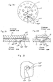
- Figs. 10-13 depict another embodiment of the present invention.
- a plan view of valve plate 11 from the discharge chamber-side is depicted.
- Discharge holes 14' and suction holes 15 are disposed equiangularly in valve plate 11 with respect to the center C.
- Figs. 11 and 12 depict the cross-sectional views of the discharge mechanism during the compression phase.
- Valve reed 12 is fixed between valve plate 11 and valve retainer 13.
- Discharge hole 14' includes partially convex sidewall 16' and cylindrical portion 19'.
- Small circular opening 16a' is the piston cylinder-end circumference of sidewall 16'.
- Large elliptical opening 16b' is the discharge chamber-end opening of sidewall 16'.
- large elliptical opening 16b' extends to only the radially outer side of discharge hole 14' with respect to center C of valve plate 11.
- hole area Sa' is defined by small circular opening 16a'
- hole area Sb' is defined by large elliptical opening 16b'.
- area Sb' is about 1.5 times greater than area Sa'.
- the curve of partially tapered sidewall 16' allows area Sa' on the piston cylinder-side surface of valve plate 11 to increase gradually to area Sb' on the discharge chamber-side surface of valve plate 11.
- the circumference of discharge hole 14' increases from the piston cylinder-side surface to the discharge chamber-side surface of valve plate 11.
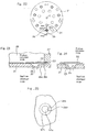
- Figs. 14-17 depict another embodiment of the present invention.
- a plan view of valve plate 11 from the discharge chamber side is depicted.
- Discharge holes 14'' and suction holes 15 are disposed equiangularly in valve plate 11 with respect to the center C.
- valve seat grooves 110 are provided around each discharge hole 14''. Valve seat groove 110 prevents valve reed 12 from sticking to valve place 11.
- Figs. 15 and 16 depict the cross-sectional view of the discharge mechanism during the compression phase.
- Valve reed 12 is fixed between valve plate 11 and valve retainer 13.
- Discharge hole 14'' comprises a tapered sidewall 16'' and a perpendicular part 17''.
- Small circular opening 16a'' is the piston cylinder-end opening of perpendicular part 17''.
- Large circular opening 16b'' is the discharge chamber-end opening of sidewall 16''.
- opening area Sa'' is defined by small circular opening 16a'' and opening area Sb'' is defined by large circular opening 16b''.
- area Sb'' is approximately 1.5 times greater than area Sa''. Therefore, tapered sidewall 16'' allows area Sa'' on the piston cylinder-side surface of valve plate 11 to increase gradually to area Sb'' on the discharge chamber-side surface of valve plate 11. Further, with reference to Fig. 16, the height of perpendicular part 17'' is greater than or equal to zero.
- Figs. 18-21 depict another embodiment of the present invention.
- a plan view of valve plate 11 seen from the discharge chamber-side is depicted.
- Discharge holes 14''' and suction holes 15 are disposed equiangularly in valve plate 11 with respect to center C.
- Figs. 19 and 20 depict the cross-sectional view of the discharge mechanism during the compression phase.
- Valve reed 12 is fixed between valve plate 11 and valve retainer 13.
- Discharge hole 14''' comprises a partially tapered sidewall 16''', a cylindrical portion 19''' and a perpendicular part 17'''.
- Small circular opening 16a''' is the piston cylinder-end opening of perpendicular part 17''.
- Large elliptical opening 16b''' is the discharge chamber-end opening of tapered sidewall 16'''.
- large elliptical opening 16b''' extends to the radially outer side of discharge hole 14''' with respect to center C of valve plate 11.
- opening area Sa''' is defined by small circular opening 16a'''
- opening area Sb''' is defined by large elliptical opening 16b'''.
- area Sb''' is about 1.5 times greater than area Sa'''. Therefore, partially tapered sidewall 16''' allows area Sa''' on the piston cylinder-side surface of valve plate 11 to increase gradually to area Sb''' on the discharge chamber-side surface of valve plate 11.
- Figs. 22-25 depict another embodiment of the present invention.
- a plan view of valve plate 21 from the piston cylinder-side is depicted.
- Discharge holes 24 and suction holes 25 are disposed equiangularly in valve plate 21 with respect to the center C.
- Figs. 23 and 24 depict the cross-sectional view of the suction mechanism during the suction phase.
- vibration of valve reed 22 is limited by a groove 23 provided at end of housing 27.
- Suction hole 25 includes a convex tapered sidewall 26. Small circular opening 26a is the suction chamber-end opening of tapered sidewall 26. Large circular opening 26b is the piston cylinder-end opening of tapered sidewall 26.
- opening area S2a is defined by small circular opening 26a
- opening area S2b is defined by large circular opening 26b.
- area S2b is about 1.5 times greater than area S2a.
- the curve of convex tapered sidewall 26 allows area S2a on the suction chamber-side surface of valve plate 21 to increase gradually to area S2b on the piston cylinder-side surface of valve plate 21.
- the circumference of suction hole 25 increases from the suction chamber-side surface of valve plate 21 to the piston cylinder surface.
- the shapes of the holes depicted in Fig. 6-21 and described with respect to discharge holes are applicable to and suitable for suction holes.
- the present invention provides a convex tapered sidewall or a tapered sidewall with cylindrical portions in a discharge hole or in a suction hole, or both.
- the turbulence of the refrigerant flow passing through the discharge holes or the suction holes, or both may be reduced. Accordingly, it is possible to decrease the flow resistance for the refrigerant gas through the discharge holes and suction holes, so that the volumetric efficiency of the compressor may be improved and related noise suppressed.
- the present invention is applicable to any type of compressor that has a reed valve mechanism.
- the present invention may be applied to swash plate-type compressors, wobble plate-type compressor, or scroll-type compressor.
- the present invention has been described in detail in connection with preferred embodiments, the invention is not limited thereto. It will be understood by those of ordinary skill in the art that variations and modifications may be made within the scope of this invention, as defined by the following claims.
Landscapes
- Engineering & Computer Science (AREA)
- Mechanical Engineering (AREA)
- General Engineering & Computer Science (AREA)
- Compressor (AREA)
Abstract
Description
- The present invention relates to a refrigerant compressor used for an automotive air-conditioning system. More particularly, the present invention relates to shapes of suction holes and discharge holes provided in a valve plate of a compressor.
- A description of the structure and operation of a refrigerant compressor for an automotive air conditioning system follows. Referring to Fig. 1, a
conventional compressor 100 is depicted.Compressor 100 comprisesfront housing 30,housing 27, valve plate 1, andrear housing 32. Along the central axis ofcompressor 100 is provided adrive shaft 34, which is supported rotatably byneedle bearings housing 27,cam rotor 37 which is fixed to driveshaft 34 engages the inner wall offront housing 30 via thrust bearing 38.Cam rotor 37 rotates whendrive shaft 34 is rotated.Hinge mechanism 39couples cam rotor 37 withinclined plate 40. Inclinedplate 40 rotates withcam rotor 37. Wobbleplate 43 engages withinclined plate 40 via thrust bearing 41 and needle bearing 42. A wobbling motion is induced ininclined plate 40, so thatinclined plate 40 wobbles while rotating. This motion ofinclined plate 40 transfers to wobbleplate 43. Rotation ofwobble plate 43 is inhibited by engagement with aguide bar 44. Therefore, only the wobbling component of the motion ofinclined plate 40 is transferred frominclined plate 40 towobble plate 43. Wobbleplate 43 has a wobbling motion, but does not rotate withdrive shaft 34.Rod 45 is connected by spherical coupling to wobbleplate 43 and to a plurality ofpistons 46. Whenwobble plate 43 wobbles, each ofpistons 46 reciprocates in one of a plurality ofcylinders 71. -
Suction valve reed 22,discharge valve reed 2, andvalve retainer 3 are fixed bybolt 47 to valve plate 1.Suction holes 5 anddischarge holes 4 correspond to eachpiston cylinder 71.Suction chamber 72 anddischarge chamber 70 are formed by valve plate 1 and therear housing 32; and are separated byinside partition plate 33. - When
drive shaft 34 is rotated by an external power source (not shown), eachpiston 46 reciprocates in itsrespective piston cylinder 71. Whenpiston 46 is moving leftward in Fig. 1, the suction phase is executed, and whenpiston 46 is moving rightward, the compression phase is executed. - In the suction phase, refrigerant gas in
suction chamber 72 is drawn intopiston cylinder 71 throughsuction hole 5. Due to the pressure variance betweensuction chamber 72 andpiston cylinder 71, the refrigerant gas insuction chamber 72 flows tosuction hole 5, passes throughsucktion hole 5, openssuction valve reed 22, and enterspiston cylinder 71.Suction valve reed 22 prohibits a reverse flow of refrigerant gas intosuction chamber 72 during the compression phase. - In the compression phase, the refrigerant gas in
piston cylinder 71 is discharged intodischarge chamber 70 throughdischarge hole 4. Due to the pressure variance between piston under 71 anddischarge chamber 70, the refrigerant gas passes, throughdischarge hole 4, opensdischarge valve reed 2, and entersdischarge chamber 70.Discharge valve reed 2 prohibits a reverse flow of the refrigerant gas intopiston cylinder 71 during the suction phase. - Fig. 2a depicts a cross-sectional view of valve plate 1 from the rear housing side of valve plate 1. Fig. 2b depicts a cross-sectional view of valve plate 1 from the cylinder head side of valve plate 1. With reference to Fig. 2a,
rear housing 32 is fixed tohousing 27 by a plurality ofbolts 130.Suction holes 5 anddischarge holes 4 are disposed equiangularly around the center CO and correspond topiston cylinders 71.Suction chamber 72 anddischarge chamber 70 are separated by insidepartition plate 33.Discharge valve reed 2 withininside partition plate 33 is substantially star-shaped. The arms ofdischarge valve reed 2cover discharge holes 4. With reference to Fig. 2b,suction valve reed 22 also is substantially star-shaped. Within each arm, ahole 22h enables the discharge gas to flow therethrough. - Fig. 3 depicts valve plate 1 as viewed from the side of valve plate 1 facing
discharge chamber 70.Discharge holes 4 andsuction holes 5 are disposed equiangularly with respect to the center C of valve plate 1. Fig. 4 and Fig. 5 are corresponding radial, cross-sectional views of valve plate 1 of Fig. 1. Valvereed 2 is fixed between valve plate 1 andvalve retainer 3.Discharge holes 4 have side walls which are substantially perpendicular to the opposing surfaces of valve plate 1. - Fig. 4 and Fig. 5 depict valve plate 1 during the compression phase. When the refrigerant gas is discharged from
cylinders 71, it strikes, pushes, and displacesvalve reed 2. The refrigerant gas flows intodischarge chamber 70 through a gap created betweenvalve reed 2 and valve plate 1. When refrigerant gas flow impinges againstreed valve 2 in Fig. 4, its flow path may be diverted at an angle substantially perpendicular to valve plate 1. Turbulence in the refrigerant gas flow may be created due to the abrupt change in the direction of flow. Further, a portion of the refrigerant gas flow impinging againstvalve reed 2 may not enterdischarge chamber 70, and may instead return topiston cylinder 71. These turbulence effects are indicated by the arrows in Fig. 4 and Fig. 5. Therefore, turbulence of the refrigerant gas flow may result in flow resistance atdischarge hole 4. Such flow resistance lowers the volumetric efficiency, a primary measure of the performance ofcompressor 100. The turbulence of flow also disturbs the motion ofvalve reed 2 and impedesvalve reed 2 from discretely and completely opening and closing. Moreover, the turbulence of flow indischarge holes 4 may cause noise incompressor 100. Similar problems may occur with respect tosuction holes 5. - Thus, it has long been desired to resolve effectively the problem of the turbulence - of refrigerant gas flowing through the suction holes and discharge holes and to suppress noise generated thereby.
- Therefore, a need has arisen to effectively resolve the problem of turbulence of refrigerant gas flowing through the suction holes and discharge holes, so that refrigerant flow is not impeded, and noise is suppressed. It is an object of the present invention to provide a shape for such suction holes and discharge holes in a valve plate of a compressor that improves the volumetric efficiency of the compressor and suppresses noise. It is another object of the present invention to provide shapes of such suction holes and discharge holes that may suppress the occurrence of turbulence of the refrigerant gas flow to lower impedance to refrigerant gas passing through the suction holes or the discharge holes, or both.
- A compressor according to the present invention is equipped with a valve plate that has suction passages and discharge passages. Regarding the discharge passages, each of the discharge passages includes a first piston cylinder-side opening having an area, a discharge chamber-side opening having an area, and a sidewall extending between the openings. At least a portion of the discharge passage sidewall is tapered. The discharge chamber-side opening area is greater than the piston cylinder-side opening area. Regarding the suction passages, each of the suction passages includes a second piston cylinder-side opening having an area, a suction chamber-side opening having an area, and a sidewall extending between the openings. At least a portion of the suction passage sidewall is tapered. The piston cylinder-side opening area is greater than the suction chamber-side opening area. The sidewalls of the passages may include a substantially cylindrical portion. Further, the tapered portion of the sidewalls of the passages may be less than the thickness of the valve plate. Even with partial tapering, the objects of the present invention may be achieved.
- Along the tapered sidewalls of suction holes or discharge holes, or both, the flow path of the refrigerant gas may bend gradually. The flow path of the refrigerant gas does not strike the valve reed perpendicularly, but instead flows along the tapered portion of the sidewall. As a result, any turbulence of the refrigerant is reduced in the suction holes or discharge holes, so that the volumetric efficiency of the compressor may be improved and associated noise suppressed.
- Other objects, features, and advantages of this invention will be understood from the following detailed description of the preferred embodiment of this invention with reference to the attached drawings.
- For a more complete understanding of the present invention and its advantages reference is now made to the following description taken in conjunction with the accompanying drawings, wherein like reference numerals represent like parts.
- Fig. 1 is a cross-sectional view of a conventional compressor:
- Fig. 2a is a cross-sectional view along line IIa-IIa depicted in Fig. 1.
- Fig. 2b is a cross-sectional view along line IIb-IIb depicted in Fig. 1.
- Fig. 3 is a plan view of a valve plate according to the compressor of Fig. 1.
- Fig. 4 is a cross-sectional view along line IV-IV of the valve plate depicted in Fig. 3.
- Fig. 5 is a cross-sectional view along line V-V of the valve plate depicted in Fig. 3.
- Fig. 6 is a plan view of a valve plate according to an embodiment of the present invention.
- Fig. 7 is a cross-sectional view along line VII-VII of the valve plate depicted in Fig. 6.
- Fig. 8 is a cross-sectional view along line VIII-VIII of the valve plate depicted in Fig. 6.
- Fig. 9 is a partial plan view of the discharge hole depicted in Fig. 6.
- Fig. 10 is a plan view of a valve plate according to another embodiment of the present invention.
- Fig. 11 is a cross-sectional view along fine XI-XI of the valve plate depicted in Fig. 10.
- Fig. 12 is a cross-sectional view along line XII-XII of the valve plate depicted in Fig. 10.
- Fig. 13 is a partial plan view of the discharge hole depicted in Fig. 10.
- Fig. 14 is a plan view of a valve plate according to another embodiment of the present invention.
- Fig. 15 is a cross-sectional view along line XV-XV of the valve plate depicted in Fig. 14.
- Fig. 16 is a cross-sectional view along line XVI-XVI of the valve plate depicted in Fig. 14.
- Fig. 17 is a partial plan view of the discharge hole depicted in Fig. 14.
- Fig. 18 is a plan view of a valve plate according to another embodiment of the present invention.
- Fig. 19 is a cross-sectional view along line XIX-XIX of the valve plate depicted in Fig. 18.
- Fig. 20 is a cross-sectional view along line XX-XX of the valve plate depicted in Fig. 18.
- Fig. 21 is a partial plan view of the discharge hole depicted in Fig. 18.
- Fig. 22 is a plan view of a valve plate according to another embodiment of the present invention.
- Fig. 23 is a cross-sectional view alone line XXIII-XXIII of the valve plate depicted in Fig. 22.
- Fig. 24 is a cross-sectional view along line XXIV-XXIV of the valve plate depicted in Fig. 22.
- Fig. 25 is a partial plan view of the suction hole depicted in Fig. 22.
-
- Embodiments of the present invention are illustrated in Figs. 6-25, wherein like numerals are used to denote elements that correspond to like elements depicted in Figs. 6-25. A detailed explanation of several elements and characteristics of related art compressors has been provided above and, therefore, is here omitted.
- Referring to Fig. 6, a plan view of a
valve plate 11 fromdischarge chamber 70 in accordance to an embodiment of the present invention is depicted. Discharge holes 14 and suction holes 15 are disposed equiangularly invalve plate 11 with respect to center C. Figs. 7 and 8 are cross-sectional views of the discharge mechanism during a compression phase.Valve reed 12 is fixed betweenvalve plate 11 andvalve retainer 13. Asidewall 16 ofdischarge hole 14 is formed as a convex tapered surface. Smallcircular opening 16a is on the piston cylinder end ofsidewall 16.
Largecircular opening 16b is on the discharge chamber end ofsidewall 16. - Referring to Fig. 9, hole area Sa is defined by small
circular opening 16a, and hole area Sb is defined by largecircular opening 16b. - In an embodiment of the present invention, area Sb is about 1.5 times greater than area Sa. The curve of
sidewall 16 allows area Sa on the piston cylinder-side surface ofvalve plate 11 to increase gradually to area Sb on the discharge chamber-side surface ofvalve plate 11. Thus the circumference ofdischarge hole 14 increases from the piston cylinder-side surface to the discharge chamber-side surface ofvalve plate 11. According to the present invention, a viscous fluid that flows near a wall of a chamber, or tube, flows along the surface. Being a viscous fluid, the refrigerant gas flows alongsidewall 16 whendischarge hole 14 is open, as indicated by the arrows in Fig. 7 and Fig. 8. The direction of flow of the refrigerant gas gradually bends in a lateral direction according to Figs. 7 and 8. The refrigerant gas is prevented from colliding directly uponvalve reed 12. As a result, turbulence of the refrigerant gas withindischarge hole 14 is reduced. Therefore, the shape ofdischarge hole 14 improves the volumetric efficiency ofcompressor 100. - Figs. 10-13 depict another embodiment of the present invention. Referring to Fig. 10, a plan view of
valve plate 11 from the discharge chamber-side is depicted. Discharge holes 14' and suction holes 15 are disposed equiangularly invalve plate 11 with respect to the center C. Figs. 11 and 12 depict the cross-sectional views of the discharge mechanism during the compression phase.Valve reed 12 is fixed betweenvalve plate 11 andvalve retainer 13. Discharge hole 14' includes partially convex sidewall 16' and cylindrical portion 19'. Smallcircular opening 16a' is the piston cylinder-end circumference of sidewall 16'. Largeelliptical opening 16b' is the discharge chamber-end opening of sidewall 16'. - In this embodiment, large
elliptical opening 16b' extends to only the radially outer side of discharge hole 14' with respect to center C ofvalve plate 11. Referring to Fig. 13, hole area Sa' is defined by smallcircular opening 16a', and hole area Sb' is defined by largeelliptical opening 16b'. In this embodiment, area Sb' is about 1.5 times greater than area Sa'. The curve of partially tapered sidewall 16' allows area Sa' on the piston cylinder-side surface ofvalve plate 11 to increase gradually to area Sb' on the discharge chamber-side surface ofvalve plate 11. Thus, the circumference of discharge hole 14' increases from the piston cylinder-side surface to the discharge chamber-side surface ofvalve plate 11. - Figs. 14-17 depict another embodiment of the present invention. Referring to Fig. 14, a plan view of
valve plate 11 from the discharge chamber side is depicted. Discharge holes 14'' and suction holes 15 are disposed equiangularly invalve plate 11 with respect to the center C. On the surface ofvalve plate 11,valve seat grooves 110 are provided around each discharge hole 14''.Valve seat groove 110 preventsvalve reed 12 from sticking tovalve place 11. - Figs. 15 and 16 depict the cross-sectional view of the discharge mechanism during the compression phase.
Valve reed 12 is fixed betweenvalve plate 11 andvalve retainer 13. Discharge hole 14'' comprises a tapered sidewall 16'' and a perpendicular part 17''. Smallcircular opening 16a'' is the piston cylinder-end opening of perpendicular part 17''. Largecircular opening 16b'' is the discharge chamber-end opening of sidewall 16''. - Referring to Fig. 17, opening area Sa'' is defined by small
circular opening 16a'' and opening area Sb'' is defined by largecircular opening 16b''. In this embodiment, area Sb'' is approximately 1.5 times greater than area Sa''. Therefore, tapered sidewall 16'' allows area Sa'' on the piston cylinder-side surface ofvalve plate 11 to increase gradually to area Sb'' on the discharge chamber-side surface ofvalve plate 11. Further, with reference to Fig. 16, the height of perpendicular part 17'' is greater than or equal to zero. - Figs. 18-21 depict another embodiment of the present invention. Referring to Fig. 18, a plan view of
valve plate 11 seen from the discharge chamber-side is depicted. Discharge holes 14''' and suction holes 15 are disposed equiangularly invalve plate 11 with respect to center C. Figs. 19 and 20 depict the cross-sectional view of the discharge mechanism during the compression phase.Valve reed 12 is fixed betweenvalve plate 11 andvalve retainer 13. Discharge hole 14''' comprises a partially tapered sidewall 16''', a cylindrical portion 19''' and a perpendicular part 17'''. Smallcircular opening 16a''' is the piston cylinder-end opening of perpendicular part 17'''. Largeelliptical opening 16b''' is the discharge chamber-end opening of tapered sidewall 16'''. - In this embodiment, large
elliptical opening 16b''' extends to the radially outer side of discharge hole 14''' with respect to center C ofvalve plate 11. Referring to Fig. 21, opening area Sa''' is defined by smallcircular opening 16a''', and opening area Sb''' is defined by largeelliptical opening 16b'''. In this embodiment, area Sb''' is about 1.5 times greater than area Sa'''. Therefore, partially tapered sidewall 16''' allows area Sa''' on the piston cylinder-side surface ofvalve plate 11 to increase gradually to area Sb''' on the discharge chamber-side surface ofvalve plate 11. - Figs. 22-25 depict another embodiment of the present invention. Referring to Fig. 22, a plan view of
valve plate 21 from the piston cylinder-side is depicted. Discharge holes 24 and suction holes 25 are disposed equiangularly invalve plate 21 with respect to the center C. Figs. 23 and 24 depict the cross-sectional view of the suction mechanism during the suction phase. With reference to Fig. 23, vibration ofvalve reed 22 is limited by agroove 23 provided at end ofhousing 27.Suction hole 25 includes a convex taperedsidewall 26. Smallcircular opening 26a is the suction chamber-end opening of taperedsidewall 26. Largecircular opening 26b is the piston cylinder-end opening of taperedsidewall 26. - Referring to Fig. 25, opening area S2a is defined by small
circular opening 26a, and opening area S2b is defined by largecircular opening 26b. In this embodiment, area S2b is about 1.5 times greater than area S2a. The curve of convex taperedsidewall 26 allows area S2a on the suction chamber-side surface ofvalve plate 21 to increase gradually to area S2b on the piston cylinder-side surface ofvalve plate 21. Thus, the circumference ofsuction hole 25 increases from the suction chamber-side surface ofvalve plate 21 to the piston cylinder surface. The shapes of the holes depicted in Fig. 6-21 and described with respect to discharge holes are applicable to and suitable for suction holes. - Thus, the present invention provides a convex tapered sidewall or a tapered sidewall with cylindrical portions in a discharge hole or in a suction hole, or both. As a result, the turbulence of the refrigerant flow passing through the discharge holes or the suction holes, or both, may be reduced. Accordingly, it is possible to decrease the flow resistance for the refrigerant gas through the discharge holes and suction holes, so that the volumetric efficiency of the compressor may be improved and related noise suppressed.
- The present invention is applicable to any type of compressor that has a reed valve mechanism. For example, the present invention may be applied to swash plate-type compressors, wobble plate-type compressor, or scroll-type compressor. Although the present invention has been described in detail in connection with preferred embodiments, the invention is not limited thereto. It will be understood by those of ordinary skill in the art that variations and modifications may be made within the scope of this invention, as defined by the following claims.
Claims (10)
- A compressor having a discharge valve mechanism, comprising:a valve plate (11) having at least one discharge passage (14) for providing fluid communication between a piston cylinder (71) and a discharge chamber (70), a discharge valve reed (2), and a valve retainer (3), andsaid at least one discharge passage (14) comprising a first piston cylinder-side opening (16a) having an area (Sa), a discharge chamber-side opening (16b) having an area (Sb) and a sidewall (16) extending between said openings,
characterized in that at least a portion of said discharge passage sidewall (16) is tapered, and wherein said discharge chamber-side opening area (Sb) is greater than said first piston cylinder-side opening area (Sa). - The compressor of claim 1, wherein said valve plate (11) has a valve plate thickness and said tapered discharge passage sidewall portion (16'') has a tapered sidewall height, such that said valve plate thickness is greater than said tapered sidewall height.
- The compressor of claim 1 or 2, wherein said discharge passage sidewall (16', 16''') further includes a substantially cylindrical portion (19', 19''').
- The compressor of one of claims 1 to 3, wherein said first piston cylinder-side opening (16a) has a circular or elliptical circumferential shape and/or said discharge chamber-side opening (16b, 16b') has a circular or elliptical circumferential shape.
- The compressor of one of claims 1 to 4, further comprising:a suction valve mechanism comprising said valve plate (11) having at least one suction passage (15) for providing fluid communication between a suction chamber (72) and said piston cylinder (71), a suction valve reed (22), and a means (23) for limiting a motion of said suction valve reed (22), wherein said at least one suction passage (15) has a second piston cylinder-side opening having an area, a suction chamber-side opening having an area, and a sidewall extending between said openings, wherein at least a portion of said suction passage sidewall is tapered, and wherein said second piston cylinder-side opening area is greater than said suction chamber-side opening area.
- A compressor having a suction valve mechanism, comprising:a valve plate (21) having at least one suction passage (25) providing fluid communication between a suction chamber (72) and a piston cylinder (71), a suction valve reed (22), and a means (23) for limiting a motion of said suction valve reed (22); andsaid at least one suction passage (25) comprises a first piston cylinder-side opening (26b) having an area (52a), a suction chamber-side opening (26a) having an area (52b), and a sidewall (26) extending between said openings,
characterized in thatat least a portion of said suction passage sidewall (26) is tapered, and wherein said first piston cylinder-side opening area (52b) is greater than said suction chamber-side opening area (52a). - The compressor of claim 6, wherein said valve plate (21) has a valve plate thickness and said tapered suction passage sidewall portion has a tapered sidewall height, such that said valve plate thickness is greater than said tapered sidewall height.
- The compressor of claim 6 or 7, wherein said suction passage sidewall (26) further includes a substantially cylindrical portion.
- The compressor of one of claims 6 to 8, wherein said suction chamber-side opening (26a) has a circular or elliptical circumferential shape, and/orsaid piston cylinder-side opening (26b) has a circular or elliptical circumferential shape.
- The compressor of one of claims 6 to 9, further comprising:a discharge valve mechanism comprising said valve plate (21) having at least one discharge passage (24) providing fluid communication between a discharge chamber (70) and said piston cylinder (71), a discharge valve reed (2), and a valve retainer (3), wherein said at least one discharge passage (24) has a second piston cylinder-side opening having an area, a discharge chamber-side opening having an area, and a sidewall extending between said openings, wherein at least a portion of said discharge passage sidewall is tapered, and wherein said discharge chamber-side opening area is greater than said second piston cylinder-side opening area.
Applications Claiming Priority (2)
| Application Number | Priority Date | Filing Date | Title |
|---|---|---|---|
| JP36003797 | 1997-12-26 | ||
| JP36003797 | 1997-12-26 |
Publications (3)
| Publication Number | Publication Date |
|---|---|
| EP0926345A2 true EP0926345A2 (en) | 1999-06-30 |
| EP0926345A3 EP0926345A3 (en) | 2000-03-08 |
| EP0926345B1 EP0926345B1 (en) | 2001-10-24 |
Family
ID=18467580
Family Applications (1)
| Application Number | Title | Priority Date | Filing Date |
|---|---|---|---|
| EP19980124026 Expired - Lifetime EP0926345B1 (en) | 1997-12-26 | 1998-12-17 | Shape of suction hole and discharge hole of refrigerant compressor |
Country Status (3)
| Country | Link |
|---|---|
| EP (1) | EP0926345B1 (en) |
| KR (1) | KR100552312B1 (en) |
| DE (1) | DE69802160T2 (en) |
Cited By (3)
| Publication number | Priority date | Publication date | Assignee | Title |
|---|---|---|---|---|
| FR2787869A1 (en) * | 1998-12-24 | 2000-06-30 | Sanden Corp | REFRIGERANT COMPRESSOR |
| EP2886864A4 (en) * | 2012-07-25 | 2016-09-21 | Daikin Ind Ltd | CONDENSER |
| EP4098171A2 (en) | 2021-05-14 | 2022-12-07 | BSH Hausgeräte GmbH | Household appliance with a compressor containing a reed valve |
Family Cites Families (6)
| Publication number | Priority date | Publication date | Assignee | Title |
|---|---|---|---|---|
| GB760815A (en) * | 1953-04-23 | 1956-11-07 | Carrier Engineering Co Ltd | Improvements in or relating to reciprocating compressors |
| DE2451207C3 (en) * | 1974-10-29 | 1981-10-29 | Robert Bosch Gmbh, 7000 Stuttgart | Valve seat plate for a reciprocating compressor |
| US4580604A (en) * | 1983-06-23 | 1986-04-08 | Mitsubishi Denki Kabushiki Kaisha | Discharging valve device for a compressor |
| US4642037A (en) * | 1984-03-08 | 1987-02-10 | White Consolidated Industries, Inc. | Reed valve for refrigeration compressor |
| HU198788B (en) * | 1986-04-07 | 1989-11-28 | Finoszerelvenygyar | Pressure valve system of piston cooling compressor |
| JP2709967B2 (en) * | 1989-11-28 | 1998-02-04 | 三田工業株式会社 | Automatic document feeder |
-
1998
- 1998-12-17 EP EP19980124026 patent/EP0926345B1/en not_active Expired - Lifetime
- 1998-12-17 DE DE1998602160 patent/DE69802160T2/en not_active Expired - Lifetime
- 1998-12-24 KR KR1019980058051A patent/KR100552312B1/en not_active Expired - Fee Related
Non-Patent Citations (1)
| Title |
|---|
| None |
Cited By (4)
| Publication number | Priority date | Publication date | Assignee | Title |
|---|---|---|---|---|
| FR2787869A1 (en) * | 1998-12-24 | 2000-06-30 | Sanden Corp | REFRIGERANT COMPRESSOR |
| DE19962050C2 (en) * | 1998-12-24 | 2002-06-13 | Sanden Corp | Compressor with an exhaust valve mechanism and an intake valve mechanism |
| EP2886864A4 (en) * | 2012-07-25 | 2016-09-21 | Daikin Ind Ltd | CONDENSER |
| EP4098171A2 (en) | 2021-05-14 | 2022-12-07 | BSH Hausgeräte GmbH | Household appliance with a compressor containing a reed valve |
Also Published As
| Publication number | Publication date |
|---|---|
| KR19990066867A (en) | 1999-08-16 |
| KR100552312B1 (en) | 2006-05-23 |
| DE69802160D1 (en) | 2001-11-29 |
| DE69802160T2 (en) | 2002-06-06 |
| EP0926345A3 (en) | 2000-03-08 |
| EP0926345B1 (en) | 2001-10-24 |
Similar Documents
| Publication | Publication Date | Title |
|---|---|---|
| KR100485424B1 (en) | Capacity variable type compressor | |
| EP0697521B1 (en) | Valved discharge mechanism of a refrigerant compressor | |
| US6318980B1 (en) | Shape of suction hole and discharge hole of refrigerant compressor | |
| US20220090600A1 (en) | Scroll compressor | |
| EP1008751B1 (en) | Compressor | |
| US6419467B1 (en) | Structure for suction valve of piston type compressor | |
| US4863356A (en) | Multi-cylinder refrigerant gas compressor with a muffling arrangement | |
| JP3860311B2 (en) | Swash plate compressor | |
| EP0926345B1 (en) | Shape of suction hole and discharge hole of refrigerant compressor | |
| EP2354548B1 (en) | Variable displacement type reciprocating compressor | |
| US6012905A (en) | Suction and discharge valve mechanism for fluid displacement apparatus | |
| US20020141880A1 (en) | Easy method for manufacturing swash plate and variable capacity compressor adopting the swash plate | |
| EP1394410B1 (en) | Compressor having reduced pressure pulsation | |
| EP0911519B1 (en) | Housing for the valve plate assembly of a swash plate compressor | |
| JP2003161255A (en) | Swash plate type compressor | |
| EP1184569A2 (en) | Swash plate type compressor having pulsation damping structure | |
| US8118566B2 (en) | Piston compressor with second intake | |
| EP1983191B1 (en) | Variable displacement-type clutchless compressor | |
| JP4185696B2 (en) | Compressor mounting structure | |
| US20050196291A1 (en) | Piston compressor | |
| US6179576B1 (en) | Reciprocating compressor | |
| JP2001132625A (en) | One side swash plate compressor | |
| US6378417B1 (en) | Swash plate compressor in which an opening edge of each cylinder bore has a plurality of chamferred portions | |
| KR101090559B1 (en) | Swash plate type compressor | |
| KR101184211B1 (en) | Compressor |
Legal Events
| Date | Code | Title | Description |
|---|---|---|---|
| PUAI | Public reference made under article 153(3) epc to a published international application that has entered the european phase |
Free format text: ORIGINAL CODE: 0009012 |
|
| AK | Designated contracting states |
Kind code of ref document: A2 Designated state(s): DE FR |
|
| AX | Request for extension of the european patent |
Free format text: AL;LT;LV;MK;RO;SI |
|
| PUAL | Search report despatched |
Free format text: ORIGINAL CODE: 0009013 |
|
| AK | Designated contracting states |
Kind code of ref document: A3 Designated state(s): AT BE CH CY DE DK ES FI FR GB GR IE IT LI LU MC NL PT SE |
|
| AX | Request for extension of the european patent |
Free format text: AL;LT;LV;MK;RO;SI |
|
| 17P | Request for examination filed |
Effective date: 20000504 |
|
| 17Q | First examination report despatched |
Effective date: 20000802 |
|
| AKX | Designation fees paid |
Free format text: DE FR |
|
| GRAG | Despatch of communication of intention to grant |
Free format text: ORIGINAL CODE: EPIDOS AGRA |
|
| GRAG | Despatch of communication of intention to grant |
Free format text: ORIGINAL CODE: EPIDOS AGRA |
|
| GRAH | Despatch of communication of intention to grant a patent |
Free format text: ORIGINAL CODE: EPIDOS IGRA |
|
| GRAH | Despatch of communication of intention to grant a patent |
Free format text: ORIGINAL CODE: EPIDOS IGRA |
|
| GRAA | (expected) grant |
Free format text: ORIGINAL CODE: 0009210 |
|
| AK | Designated contracting states |
Kind code of ref document: B1 Designated state(s): DE FR |
|
| REF | Corresponds to: |
Ref document number: 69802160 Country of ref document: DE Date of ref document: 20011129 |
|
| ET | Fr: translation filed | ||
| PLBE | No opposition filed within time limit |
Free format text: ORIGINAL CODE: 0009261 |
|
| STAA | Information on the status of an ep patent application or granted ep patent |
Free format text: STATUS: NO OPPOSITION FILED WITHIN TIME LIMIT |
|
| 26N | No opposition filed | ||
| PGFP | Annual fee paid to national office [announced via postgrant information from national office to epo] |
Ref country code: DE Payment date: 20141211 Year of fee payment: 17 |
|
| PGFP | Annual fee paid to national office [announced via postgrant information from national office to epo] |
Ref country code: FR Payment date: 20141219 Year of fee payment: 17 |
|
| REG | Reference to a national code |
Ref country code: DE Ref legal event code: R082 Ref document number: 69802160 Country of ref document: DE Representative=s name: PRUEFER & PARTNER MBB PATENTANWAELTE RECHTSANW, DE Ref country code: DE Ref legal event code: R081 Ref document number: 69802160 Country of ref document: DE Owner name: SANDEN HOLDINGS CORPORATION, LSESAKI-SHI, JP Free format text: FORMER OWNER: SANDEN CORP., ISESAKI, GUNMA, JP |
|
| REG | Reference to a national code |
Ref country code: FR Ref legal event code: CD Owner name: SANDEN HOLDINGS CORPORATION, JP Effective date: 20160525 |
|
| REG | Reference to a national code |
Ref country code: DE Ref legal event code: R119 Ref document number: 69802160 Country of ref document: DE |
|
| REG | Reference to a national code |
Ref country code: FR Ref legal event code: ST Effective date: 20160831 |
|
| PG25 | Lapsed in a contracting state [announced via postgrant information from national office to epo] |
Ref country code: DE Free format text: LAPSE BECAUSE OF NON-PAYMENT OF DUE FEES Effective date: 20160701 |
|
| PG25 | Lapsed in a contracting state [announced via postgrant information from national office to epo] |
Ref country code: FR Free format text: LAPSE BECAUSE OF NON-PAYMENT OF DUE FEES Effective date: 20151231 |