EP0926085B1 - Dual document singulating apparatus for a mail handling system - Google Patents
Dual document singulating apparatus for a mail handling system Download PDFInfo
- Publication number
- EP0926085B1 EP0926085B1 EP98119495A EP98119495A EP0926085B1 EP 0926085 B1 EP0926085 B1 EP 0926085B1 EP 98119495 A EP98119495 A EP 98119495A EP 98119495 A EP98119495 A EP 98119495A EP 0926085 B1 EP0926085 B1 EP 0926085B1
- Authority
- EP
- European Patent Office
- Prior art keywords
- documents
- assembly
- stack
- document
- feed
- Prior art date
- Legal status (The legal status is an assumption and is not a legal conclusion. Google has not performed a legal analysis and makes no representation as to the accuracy of the status listed.)
- Expired - Lifetime
Links
- 230000009977 dual effect Effects 0.000 title 1
- 238000012545 processing Methods 0.000 claims description 18
- 230000032258 transport Effects 0.000 claims description 16
- 230000007246 mechanism Effects 0.000 claims description 9
- 230000000712 assembly Effects 0.000 claims description 5
- 238000000429 assembly Methods 0.000 claims description 5
- 230000002441 reversible effect Effects 0.000 claims description 5
- 238000011144 upstream manufacturing Methods 0.000 description 16
- 238000000926 separation method Methods 0.000 description 10
- 238000000034 method Methods 0.000 description 4
- 230000008569 process Effects 0.000 description 4
- 238000000418 atomic force spectrum Methods 0.000 description 2
- 238000004891 communication Methods 0.000 description 2
- 238000013461 design Methods 0.000 description 2
- 239000002783 friction material Substances 0.000 description 2
- 238000012986 modification Methods 0.000 description 2
- 230000004048 modification Effects 0.000 description 2
- 239000000758 substrate Substances 0.000 description 2
- 239000004809 Teflon Substances 0.000 description 1
- 229920006362 Teflon® Polymers 0.000 description 1
- 230000001419 dependent effect Effects 0.000 description 1
- 230000003993 interaction Effects 0.000 description 1
Images

Classifications
-
- B—PERFORMING OPERATIONS; TRANSPORTING
- B65—CONVEYING; PACKING; STORING; HANDLING THIN OR FILAMENTARY MATERIAL
- B65H—HANDLING THIN OR FILAMENTARY MATERIAL, e.g. SHEETS, WEBS, CABLES
- B65H3/00—Separating articles from piles
- B65H3/02—Separating articles from piles using friction forces between articles and separator
- B65H3/04—Endless-belt separators
- B65H3/045—Endless-belt separators for separating substantially vertically stacked articles
-
- B—PERFORMING OPERATIONS; TRANSPORTING
- B65—CONVEYING; PACKING; STORING; HANDLING THIN OR FILAMENTARY MATERIAL
- B65H—HANDLING THIN OR FILAMENTARY MATERIAL, e.g. SHEETS, WEBS, CABLES
- B65H3/00—Separating articles from piles
- B65H3/46—Supplementary devices or measures to assist separation or prevent double feed
- B65H3/52—Friction retainers acting on under or rear side of article being separated
- B65H3/5246—Driven retainers, i.e. the motion thereof being provided by a dedicated drive
-
- B—PERFORMING OPERATIONS; TRANSPORTING
- B65—CONVEYING; PACKING; STORING; HANDLING THIN OR FILAMENTARY MATERIAL
- B65H—HANDLING THIN OR FILAMENTARY MATERIAL, e.g. SHEETS, WEBS, CABLES
- B65H2301/00—Handling processes for sheets or webs
- B65H2301/30—Orientation, displacement, position of the handled material
- B65H2301/32—Orientation of handled material
- B65H2301/321—Standing on edge
-
- B—PERFORMING OPERATIONS; TRANSPORTING
- B65—CONVEYING; PACKING; STORING; HANDLING THIN OR FILAMENTARY MATERIAL
- B65H—HANDLING THIN OR FILAMENTARY MATERIAL, e.g. SHEETS, WEBS, CABLES
- B65H2701/00—Handled material; Storage means
- B65H2701/10—Handled articles or webs
- B65H2701/19—Specific article or web
- B65H2701/1916—Envelopes and articles of mail
Definitions
- the present invention relates to singulating apparatus.
- the processing and handling of mailpieces not only takes place at the Postal Service, but also occurs at each and every business or other site where communication via the mail delivery system is utilized. That is, various pieces of mail generated by a plurality of departments and individuals within a company need to be collected, sorted, addressed, and franked as part of the outgoing mail process. Additionally, incoming mail needs to be collected and sorted efficiently to ensure that it gets to the addressee in a minimal amount of time.
- US-A-4,615,519 describes a singulating apparatus comprising: a first singulator having a first retard assembly and a first feed assembly disposed opposite to each other along the document feed path, the first retard assembly and the first feed assembly cooperating together on a stack of documents being transported along the document feed path and passing between the first feed assembly and the first retard assembly to separate and transport downstream along the document feed path individual documents from the stack of documents; and a second singulator, positioned downstream along the document feed path from the first singulator, having a second retard assembly and a second feed assembly disposed opposite to each other along the document feed path, and wherein at times when a plurality of documents from the stack of documents that are in overlapping relationship with each other pass through the first singulator without being separated and are received by the second singulator, the second retard assembly and the second feed assembly cooperate together on the plurality of documents to separate and transport individual ones of the plurality of documents downstream along the document feed path.
- mixed mail is used herein to mean sets of intermixed mailpieces of varying size (postcards to 9" by 12" flats), thickness, and weight.
- mixed mail also includes stepped mail (i.e. an envelope containing therein an insert which is smaller than the envelope to create a step in the envelope), tabbed and untabbed mail products, and mailpieces made from different substrates.
- the stack of "mixed mail" is first loaded onto some type of conveying system for subsequent sorting into individual pieces.
- the stack of mixed mail is moved as a stack by an external force to, for example, a shingling device.
- the shingling device applies a force to the lead mailpiece in the stack to initiate the separation of the lead mailpiece from the rest of the stack by shingling it slightly relative to the stack.
- the shingled mailpieces are then transported downstream to, for example, a separating or singulating device which completes the separation of the lead mailpiece from the stack so that individual pieces of mail are transported further downstream for subsequent processing.
- inter-document stack forces exist between each of the mailpieces that are in contact with each other in the stack.
- the inter-document stack forces are created by the stack advance mechanism, the frictional forces between the documents, and potentially electrostatic forces that may exist between the documents.
- the inter-document forces tend to oppose the force required to shear the lead mailpiece from the stack.
- the interaction of the force used to drive the shingled stack toward the separator and the separator forces can potentially cause a thin mailpiece to be damaged as it enters the separator.
- the structure used to separate a stack of mixed mail must take into account the counterproductive nature of the forces acting on the mailpieces and be such that an effective force profile acts on the mailpieces throughout their processing cycle so that effective and reliable mailpiece separation and transport at very high processing speeds (such as four mailpieces per second) can be accomplished without physical damage occurring to the mailpieces.
- the desired force profile acting on a particular mailpiece is dependent upon the size, thickness, configuration, weight, and substrate of the individual mailpiece being processed, the design of a mixed mail feeder which can efficiently and reliably process a wide range of different types of mixed mailpieces has been extremely difficult to achieve.
- singulating apparatus for use in a device for processing documents being transported therethrough along a document feed path, the apparatus comprising: a first singulator having a first retard assembly and a first feed assembly disposed opposite to each other along the document feed path, the first retard assembly and the first feed assembly cooperating together on a stack of documents subject to a stack advance mechanism force and being transported along the document feed path and passing between the first feed assembly and the first retard assembly to separate and transport downstream along the document feed path individual documents from the stack of documents; and a second singulator, positioned downstream along the document feed path from the first singulator to receive the documents when released from the stack advance mechanism force and having a second retard assembly and a second feed assembly disposed opposite to each other along the document feed path, and wherein at times when a plurality of documents from the stack of documents that are in overlapping relationship with each other pass through the first singulator without being separated and are received by the second singulator, the second retard assembly and the second feed assembly cooperate together on the plurality of documents to separate
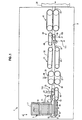
- FIG. 1 shows a mixed mail feeder 1 having conventional framework 2 upon which all of the components of the mixed mail feeder 1 are mounted.
- Mixed mail feeder 1 includes a stack advance mechanism 5 having a continuous conveyor belt 7 mounted for rotation in a conventional manner about a plurality of pulleys (not shown) in the direction of arrow "A".
- Mounted on the conveyor belt 7 in a conventional manner is an upstanding panel 9 which moves with the conveyor 7 in the direction of arrow "A".
- a stack of mixed mail 11 is placed on the conveyor belt 7 and rests against the panel 9.
- the stack of mixed mail includes a lead mailpiece 13 and a second mailpiece 15.
- the stack of mixed mail 11 is moved toward an input feed structure 17.
- Input feed structure 17 includes a belt 18 which is driven into rotation about a series of pulleys 20, at least one of which is a driven pulley. Accordingly, as the stack advance mechanism 5 forces the lead mailpiece 13 into contact with the belt 18, the lead mailpiece 13 is laterally moved away from stack of mixed mail 11. Additionally, a driven belt 19 which makes contact with the bottom edge of the lead mailpiece 13 also assists in moving the lead mailpiece 13 downstream past a guide mechanism 21 and toward a document singulating apparatus 23. As shown, the combination of the stack advance mechanism 5, the input feed structure 17, and the guide plate 21 help to present the mailpieces which are removed from the stack of mixed mail 11 into the document singulating apparatus 23 in a shingled manner as is more clearly shown in Figure 2.
- Document singulating apparatus 23 operates to separate the lead mailpiece 13 from the remaining stack of mixed mail 11 so that only individual mailpieces are presented to output feeding structure 25 for ultimate processing downstream to a processing station 26 where each individual mailpiece has some type of operation (metering, scanning, etc.) performed thereon.
- Output feeding structure 25 includes driven belt structures 27 and 29 which receive the mailpiece as it exits the document singulating apparatus 23 and helps to transport it downstream.
- Belt structure 29 is spring loaded by spring 30 and is moveable toward and away from belt structure 27 to accommodate different mailpiece thicknesses
- a buffer station 31 consisting of 2 driven belt structures 33, 35 help to buffer the individual mailpieces to ensure that they are aligned on their bottom edge prior to transport past a second guide plate 37 and into a second document singulating apparatus 39. Subsequent to passage through the second document singulating apparatus 39, the individual mailpieces are transported into a second output feed structure 41 which acts on the mailpieces together with a driven belt structure 42 to transport the individual mailpieces to the processing station 26.
- belt 42 acts on the bottom edges of the mailpieces transporting them through buffer station 31.
- the belt structures 33, 35 are separated from each other on each side of the mailpiece feed path 51 by a distance of approximately 1.5 inches (about 3.75 cm). This spacing allows most multi-feeds which leave separator 23 to be transported through buffer station 31 without any large inter-document forces existing between the mailpieces because no significant normal feed force is present when the mailpieces are fed by belt 42. Additionally, it has been found that by utilizing the driven belts 33, 35 mailpieces which curl up in buffer station 31 are still transported out of buffer station 31. If the driven belts 33, 35 were replaced with fixed wall structures curled mailpieces might get stuck in the buffer station 31 causing a jam condition.
- each of the individual mailpieces are preferably uprightly oriented on their lower edge and have oppositely outwardly facing, upright, surfaces 24 and 26.
- Each of the individual documents in the stack of shingled mailpieces 43 is slidably movable, out of engagement with the adjacent document, against an inter-document frictional force 45 developed between the adjacent ones of surfaces 24 and 26 in the course of such disengagement.
- the document singulating apparatus 23 generally includes a deck 47 upon which the individual documents of the stack of shingled mailpieces 43 are fed.
- the deck 47 is preferably a horizontally-extending conveyor belt 19 as shown, it maybe a conventional, horizontally-extending plate having an upper surface which is coated with a low coefficient of friction material, such as Teflon or delring. The low coefficient of friction material reduces the frictional resistance to the sliding movement thereon of the lower edges of the individual documents.
- the document singulating apparatus 23 includes a feed assembly 49 for feeding each individual document of the stack of shingled mailpieces 43 downstream along a path of travel 51 on the deck 47.
- Document singulating apparatus 23 further includes a retard assembly 53 for feeding each next successive document of the stack of shingled mailpieces 43 upstream relative to the path of travel 38. That is, the feed assembly 49 interacts with the lead mailpiece 13 to move it downstream along the path of travel 51 while the retard assembly 53 causes the remainder of the documents in the stack of shingled mailpieces 43 to be moved slightly upstream.
- the forces respectively exerted by the feed assembly 49 on the lead mailpiece 13 and the retard assembly on the remaining documents in the stack are sufficient to overcome the inter-document force between the lead mailpiece and the next successive document in the stack.
- Feed assembly 49 preferably includes three endless belts 54 (only one shown).
- feed assembly 49 includes a pair of vertically oriented, parallel shafts 55, 57 which are conventionally mounted to the framework 2 for rotation.
- the upstream shaft 55 is an idler shaft and the downstream shaft 57 is a drive shaft which is driven into rotation by a motor 59 via a conventional gear train 61.
- feed assembly 49 includes three idler pulleys 63 (only one of which is shown) and three driven pulleys 65 (only one shown), which are respectively, conventionally mounted for rotation on the upstream and downstream shafts 55 and 57.
- the pulleys 63 and 65 on each shaft 55 and 57 are located at substantially equally vertically-spaced intervals above the deck 47, and thus along the shafts 55 and 57.
- Each of belts 54 are looped about a corresponding pair of pulleys 55, 57 which are located at the same interval on shafts 55 and 57, respectively, whereby the belts 54 extend substantially horizontally parallel to one another above the deck 47.
- the feed assembly 49 also includes a vertically oriented guide plate 67 which is conventionally fixedly connected to the framework 2 between the upstream and downstream shafts 55 and 57.
- each belt 54 includes an upstream belt run, generally designated 69, which extends between the mid point of guide plate 67 and the upstream idler pulleys 63, and a downstream belt run generally designated 71, which extends between the mid point of guide plate 67 and downstream driven pulleys 65.
- belts 54 and thus the respective upstream and downstream belt runs, 69 and 71, are suspended parallel to one another above deck 32 for feeding documents downstream thereon.
- guide plate 67 is parallel to the path of travel 51, and is dimensioned for aligning the downstream belt runs 71 relative to the output feeding structure 25, to support belts 54 and to optimally define the path of travel 51 for feeding individual documents of the stack of shingled mailpieces 43 downstream to the output feeding structure 25.
- the retard assembly 53 includes two outboard endless belts 73 and two inboard endless belts 75.
- the retard assembly 53 includes a first section 77 and a second section 79 which are connected together for movement relative to each other.
- the outboard belts 73 are disposed around a plurality of corresponding driven pulleys 81 as well as around a plurality of idler double track pulleys 83.
- the inboard belts 75 are respectively disposed around a corresponding one of the double track pulleys 83 as well as around a corresponding idler pulley 85.
- the double track pulleys 83 are mounted on an idler shaft 87 while the idler pulleys 85 are mounted on an idler shaft 89.
- Driven pulley 81 is mounted on a shaft 91 which is selectively driven into rotation by a motor 93 via a gear train 95. Both the motor 93 associated with the feed assembly 49 and the motor 59 associated with the feed assembly 49 are controlled by a microprocessor 97.
- belt runs 99 of belts 75 of retard assembly 53 are parallel to the belt runs 71 of belts 54 of feed assembly 49.
- the belt runs 101 of the retard assembly 53 extend progressively upstream and are laterally spaced from the upstream end of, and cooperate with, the upstream belt runs 69 of the feed assembly 49 to define a wedge-shaped document entry opening, generally designated 103, into which the shingled stack of documents 43 are fed from the input feeding structure 17.
- the upstream belt runs 69 frictionally engage the upright surface 24 of the lead mailpiece 13 and feeds the same downstream relative to the path of travel 51 to a nip 105 formed by the belts 54 and 73 at the juncture of the wedge-shaped opening 103.
- the runs 101 tend to feed the documents other than the lead mailpiece 13 upstream relative to the path of travel 51. Since the downstream force 107, exerted against the document surface 24 of lead mailpiece 13 by the belt runs 69, exceeds the inter-document frictional force 28 and the upstream force 109 exerted by the belt runs 101, the lead document 13 is engaged by the upstream belt runs 71 and fed downstream into the nip 105.
- the belts 75 and pulleys 83 are laterally moved, against the resilient urging of spring 111, away from the path of travel 51 by the lead mailpiece 13 thereby the opening the nip 105 as lead mailpiece 13 is fed downstream along the path of travel 51 between the downstream belt runs 71 and 99.
- the lead mailpiece 13 is then fed downstream by the downstream belt runs 71 against an upstream frictional force 109 exerted by the belt runs 99.
- the downstream belt runs 71 and 99 define a second wedge-shaped opening generally designated 112.
- the lead mailpiece 13 is progressively moved downstream toward the pulleys 65 and 85 such that the lead mailpiece 13 progressively urges belt runs 99 out of interleaving relationship with the belt runs 71.
- the lead mailpiece 13 When the lead mailpiece 13 is fed into a nip 113 defined between pulleys 65 and 85, the lead mailpiece 13 has urged the belt 75 completely out of the interleaved relationship with the belts 54 against the resilient urging force of spring 115. The lead mailpiece 13 is then fed downstream between the pulleys 85 and 65 to the output feeding structure 25.
- the instant singulating apparatus 23 has been modified with respect to the structure of U.S. Patent No. 5,238,236 in that the motor 93 is a reversible motor which can drive shaft 91 in the direction shown in Figure 2 or in the opposite direction thereof via selection by an operator of the desired operating mode utilizing a keyboard 117 in communication with microprocessor 97. Accordingly, when individual shearable documents are manually fed into the mixed mail feeder 1, the retard assembly 53 is designated via keyboard 117 to drive belts 77 and 75 In the counterclockwise direction of Figure 2 at the same velocity as the feed belts 54 of the feed assembly 49. Thus, the feed assembly 49 and retard assembly 53 now act in cooperation together to form a positive transport device for transporting the individual shearable documents downstream without damage thereto. While the above describes one way for changing the drive direction of belts 77 and 75, one skilled in the art will recognize that manually activated gear and linkage arrangements could also be utilized as well as electromagnetic clutches for the same purpose.
- the mixed mail feeder 1 of Figure 1 incorporates the second singulating apparatus 39 downstream from the first singulating apparatus 23.
- the second singulating apparatus 39 has the same structural components as the singulating apparatus 23 and can be driven by an independent drive system similar to that used for singulating apparatus 23.
- the use of the redundant singulating apparatus structure improves the reliability of separating individual documents from each other by the simple fact that if a multi-feed does pass through the first singulating apparatus 23 it is likely that the second singulating apparatus 39 will effectively separate the documents of the multi-feed.
- the singulating nip force at singulating apparatus 23 (as well as at singulating apparatus 39) applied by each of the springs 111 and 115 can be significantly reduced which helps to prevent damage from occurring to thin mailpieces being processed through singulators 23 and 39. That is, since a second singulating apparatus 39 provides a second opportunity to separate any multi-feeds that may occur, the problems discussed above and associated with reducing the nip force in a single singulating apparatus structure are largely eliminated.
- Figure 5 shows that as the large mailpiece LM enters the nip of singulating apparatus 23 it is fed downstream by feed assembly 49. However, once small mailpiece SM reaches the same nip it is not acted upon by the reverse assembly 53. Rather, the small mailpiece is also fed downstream by feed assembly 49 creating a multi-feed out of singulator 23. However, since the feed assembly 49 and reverse assembly 53 of singulating apparatus 39 are disposed in opposition to their corresponding structure in singulating apparatus 23, if the multi-feed that has passed through singulating apparatus 23 arrives at singulating apparatus 39 the large and small mailpieces LM and SM will be separated.
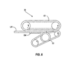
- Figure 6 show that when the multi-feed reaches singulating apparatus 39 the large mailpiece enters the nip and is fed downstream. However, when the small mailpiece SM enters the nip the reverse assembly 53 now acts on the small mailpiece SM effectively separating it from the large mailpiece LM. Finally, the buffer station 31 significantly improves the separation capability of the singulating apparatus 39 by reducing the inter-document forces between the large and small mailpieces LM and SM via its bottom edge transport and overall configuration such that separation is more easily achieved.
Landscapes
- Engineering & Computer Science (AREA)
- Mechanical Engineering (AREA)
- Sorting Of Articles (AREA)
- Sheets, Magazines, And Separation Thereof (AREA)
- Separation, Sorting, Adjustment, Or Bending Of Sheets To Be Conveyed (AREA)
- Delivering By Means Of Belts And Rollers (AREA)
- Exposure Or Original Feeding In Electrophotography (AREA)
Description
- The present invention relates to singulating apparatus.
- The processing and handling of mailpieces and other documents consumes an enormous amount of human and financial resources, particularly if the processing of the mailpieces is done manually. The processing and handling of mailpieces not only takes place at the Postal Service, but also occurs at each and every business or other site where communication via the mail delivery system is utilized. That is, various pieces of mail generated by a plurality of departments and individuals within a company need to be collected, sorted, addressed, and franked as part of the outgoing mail process. Additionally, incoming mail needs to be collected and sorted efficiently to ensure that it gets to the addressee in a minimal amount of time. Since much of the documentation and information being conveyed through the mail system is critical in nature relative to the success of a business, it is imperative that the processing and handling of both the incoming and outgoing mailpieces be done efficiently and reliably so as not to negatively impact the functioning of the business.
- US-A-4,615,519 describes a singulating apparatus comprising: a first singulator having a first retard assembly and a first feed assembly disposed opposite to each other along the document feed path, the first retard assembly and the first feed assembly cooperating together on a stack of documents being transported along the document feed path and passing between the first feed assembly and the first retard assembly to separate and transport downstream along the document feed path individual documents from the stack of documents; and a second singulator, positioned downstream along the document feed path from the first singulator, having a second retard assembly and a second feed assembly disposed opposite to each other along the document feed path, and wherein at times when a plurality of documents from the stack of documents that are in overlapping relationship with each other pass through the first singulator without being separated and are received by the second singulator, the second retard assembly and the second feed assembly cooperate together on the plurality of documents to separate and transport individual ones of the plurality of documents downstream along the document feed path.
- Reference is also directed to US-A-5,238,236.
- In view of the above, various automated mail handling machines have been developed for processing mail (removing individual pieces of mail from a stack and performing subsequent actions on each individual piece of mail). However, in order for these automatic mail handling machines to be effective, they must process and handle "mixed mail." The term "mixed mail" is used herein to mean sets of intermixed mailpieces of varying size (postcards to 9" by 12" flats), thickness, and weight. In addition, the term "mixed mail" also includes stepped mail (i.e. an envelope containing therein an insert which is smaller than the envelope to create a step in the envelope), tabbed and untabbed mail products, and mailpieces made from different substrates. Thus, the range of types and sizes of mailpieces which must be processed is extremely broad and often requires trade-offs to be made in the design of mixed mail feeding devices in order to permit effective and reliable processing of a wide variety of mixed mailpieces.
- In known mixed mail handling machines which separate and transport individual pieces of mail away from a stack of mixed mail, the stack of "mixed mail" is first loaded onto some type of conveying system for subsequent sorting into individual pieces. The stack of mixed mail is moved as a stack by an external force to, for example, a shingling device. The shingling device applies a force to the lead mailpiece in the stack to initiate the separation of the lead mailpiece from the rest of the stack by shingling it slightly relative to the stack. The shingled mailpieces are then transported downstream to, for example, a separating or singulating device which completes the separation of the lead mailpiece from the stack so that individual pieces of mail are transported further downstream for subsequent processing. In the mailing machine described immediately above, the various forces acting on the mailpieces in moving the stack, shingling the mailpieces, separating the mailpieces and moving the individual mailpieces downstream often act in a counterproductive manner relative to each other. For example, inter-document stack forces exist between each of the mailpieces that are in contact with each other in the stack. The inter-document stack forces are created by the stack advance mechanism, the frictional forces between the documents, and potentially electrostatic forces that may exist between the documents. The inter-document forces tend to oppose the force required to shear the lead mailpiece from the stack. Additionally, the interaction of the force used to drive the shingled stack toward the separator and the separator forces can potentially cause a thin mailpiece to be damaged as it enters the separator. Furthermore, in a conventional separator, there are retard belts and feeder belts that are used to separate the mailpiece from the shingled stack. Both the forces applied by the retard belts and the feeder belts must be sufficient to overcome the inter-document forces previously discussed. However, the friction force generated by the retard belts cannot be greater than that of the feeder belts or the mailpieces will not be effectively separated and fed downstream to another mail processing device. Moreover, if the feeding force being applied to the mailpieces for presenting them to the separator is too great, another potential problem which may occur is that a plurality of mailpieces (multi-feeds) will be forced through the separator without the successful separation of the mailpieces.
- In view of the above, it is recognized that large forces are desirable to act on the mailpieces to accelerate and separate the mailpieces in a reliable and high throughput manner. However, these same high forces can damage the mailpieces being processed (I.e. buckled lightweight mailpieces). Conversely, if the forces used to accelerate and separate the mailpieces are too small, poor separation, a lower throughput, and stalling of the mailpieces being processed will result. Put in another way, thin mailpieces are weak and require low forces to prevent them from being damaged, while thick/heavy mail is strong and requires high forces for proper separation and feeding. That is, when the thick/heavy mail is in the stack higher stack normal forces are created thereby increasing inter-document forces and requiring higher nip forces at the separator. Thus, the structure used to separate a stack of mixed mail must take into account the counterproductive nature of the forces acting on the mailpieces and be such that an effective force profile acts on the mailpieces throughout their processing cycle so that effective and reliable mailpiece separation and transport at very high processing speeds (such as four mailpieces per second) can be accomplished without physical damage occurring to the mailpieces. However, since the desired force profile acting on a particular mailpiece is dependent upon the size, thickness, configuration, weight, and substrate of the individual mailpiece being processed, the design of a mixed mail feeder which can efficiently and reliably process a wide range of different types of mixed mailpieces has been extremely difficult to achieve.
- It is an object of the invention to provide a singulating apparatus which separates individual documents from a stack of documents without causing damage to the individual documents.
- According to the invention, there is provided singulating apparatus for use in a device for processing documents being transported therethrough along a document feed path, the apparatus comprising: a first singulator having a first retard assembly and a first feed assembly disposed opposite to each other along the document feed path, the first retard assembly and the first feed assembly cooperating together on a stack of documents subject to a stack advance mechanism force and being transported along the document feed path and passing between the first feed assembly and the first retard assembly to separate and transport downstream along the document feed path individual documents from the stack of documents; and a second singulator, positioned downstream along the document feed path from the first singulator to receive the documents when released from the stack advance mechanism force and having a second retard assembly and a second feed assembly disposed opposite to each other along the document feed path, and wherein at times when a plurality of documents from the stack of documents that are in overlapping relationship with each other pass through the first singulator without being separated and are received by the second singulator, the second retard assembly and the second feed assembly cooperate together on the plurality of documents to separate and transport individual ones of the plurality of documents downstream along the document feed path.
- Additional objects and advantages of the invention will be set forth in the description which follows, and in part will be obvious from the description, or may be learned by practice of the invention. The objects and advantages of the invention may be realized and obtained by means of the instrumentalities and combinations particularly pointed out in the appended claims.
- The accompanying drawings, which are incorporated in and constitute a part of the specification, illustrate a presently preferred embodiment of the invention, and together with the general description given above and the detailed description of the preferred embodiment given below, serve to explain the principles of the invention. In the drawings:
- Figure 1 is a schematic top plan view of a mixed mail feeder incorporating an embodiment of the inventive singulating apparatus;
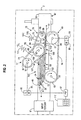
- Figure 2 is an enlarged and detailed top plan view of a singulator of Figure 1;
- Figure 3 is an enlarged and detailed top plan view of a singulator of Figure 1 but showing a lead mailpiece further ingested into its nip as compared to Figure 2;
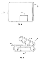
- Figure 4 shows a common multi-feed situation;
- Figure 5 shows the first singulator receiving mailpieces in an orientation that can lead to multi-feeds; and
- Figure 6 shows the second singulator receiving the same mailpieces of Figure 5.
-
- Figure 1 shows a mixed mail feeder 1 having
conventional framework 2 upon which all of the components of the mixed mail feeder 1 are mounted. Mixed mail feeder 1 includes a stack advance mechanism 5 having acontinuous conveyor belt 7 mounted for rotation in a conventional manner about a plurality of pulleys (not shown) in the direction of arrow "A". Mounted on theconveyor belt 7 in a conventional manner is anupstanding panel 9 which moves with theconveyor 7 in the direction of arrow "A". In operation, a stack of mixed mail 11 is placed on theconveyor belt 7 and rests against thepanel 9. The stack of mixed mail includes alead mailpiece 13 and asecond mailpiece 15. Thus, as theconveyor belt 7 is set into movement, the stack of mixed mail 11 is moved toward aninput feed structure 17.Input feed structure 17 includes abelt 18 which is driven into rotation about a series ofpulleys 20, at least one of which is a driven pulley. Accordingly, as the stack advance mechanism 5 forces thelead mailpiece 13 into contact with thebelt 18, thelead mailpiece 13 is laterally moved away from stack of mixed mail 11. Additionally, a drivenbelt 19 which makes contact with the bottom edge of thelead mailpiece 13 also assists in moving thelead mailpiece 13 downstream past aguide mechanism 21 and toward a document singulatingapparatus 23. As shown, the combination of the stack advance mechanism 5, theinput feed structure 17, and theguide plate 21 help to present the mailpieces which are removed from the stack of mixed mail 11 into the document singulatingapparatus 23 in a shingled manner as is more clearly shown in Figure 2. Documentsingulating apparatus 23 operates to separate thelead mailpiece 13 from the remaining stack of mixed mail 11 so that only individual mailpieces are presented tooutput feeding structure 25 for ultimate processing downstream to aprocessing station 26 where each individual mailpiece has some type of operation (metering, scanning, etc.) performed thereon. -
Output feeding structure 25 includes drivenbelt structures apparatus 23 and helps to transport it downstream.Belt structure 29 is spring loaded by spring 30 and is moveable toward and away frombelt structure 27 to accommodate different mailpiece thicknesses Abuffer station 31 consisting of 2 drivenbelt structures second guide plate 37 and into a second document singulatingapparatus 39. Subsequent to passage through the second document singulatingapparatus 39, the individual mailpieces are transported into a secondoutput feed structure 41 which acts on the mailpieces together with a drivenbelt structure 42 to transport the individual mailpieces to theprocessing station 26. It is also the case thatbelt 42 acts on the bottom edges of the mailpieces transporting them throughbuffer station 31. Moreover, thebelt structures mailpiece feed path 51 by a distance of approximately 1.5 inches (about 3.75 cm). This spacing allows most multi-feeds which leaveseparator 23 to be transported throughbuffer station 31 without any large inter-document forces existing between the mailpieces because no significant normal feed force is present when the mailpieces are fed bybelt 42. Additionally, it has been found that by utilizing the drivenbelts buffer station 31 are still transported out ofbuffer station 31. If the drivenbelts buffer station 31 causing a jam condition. - Referring to Figure 2, an enlarged view of the
document singulating structure 23 is shown. As shown,singulating apparatus 23 has received a stack of shingled mailpieces of varyingthickness 43 which has been separated from the stack of mixed mail 11 by theinput feeder 17. For the purpose of this disclosure the stack of shingledmailpieces 43 can include envelopes, with or without one or more other documents stuff therein which are or are not folded, or a sheet such as a cut sheet, which is or is not folded, or a card, remittance form, mailpiece, magazine, or other sheet, or a collation of sheets which are or are not folded. As previously discussed, each of the individual mailpieces are preferably uprightly oriented on their lower edge and have oppositely outwardly facing, upright, surfaces 24 and 26. Each of the individual documents in the stack of shingledmailpieces 43 is slidably movable, out of engagement with the adjacent document, against an inter-documentfrictional force 45 developed between the adjacent ones ofsurfaces - The
document singulating apparatus 23 generally includes adeck 47 upon which the individual documents of the stack of shingledmailpieces 43 are fed. Although thedeck 47 is preferably a horizontally-extendingconveyor belt 19 as shown, it maybe a conventional, horizontally-extending plate having an upper surface which is coated with a low coefficient of friction material, such as Teflon or delring. The low coefficient of friction material reduces the frictional resistance to the sliding movement thereon of the lower edges of the individual documents. In addition, thedocument singulating apparatus 23 includes afeed assembly 49 for feeding each individual document of the stack of shingledmailpieces 43 downstream along a path oftravel 51 on thedeck 47.Document singulating apparatus 23 further includes aretard assembly 53 for feeding each next successive document of the stack of shingledmailpieces 43 upstream relative to the path of travel 38. That is, thefeed assembly 49 interacts with thelead mailpiece 13 to move it downstream along the path oftravel 51 while theretard assembly 53 causes the remainder of the documents in the stack of shingledmailpieces 43 to be moved slightly upstream. The forces respectively exerted by thefeed assembly 49 on thelead mailpiece 13 and the retard assembly on the remaining documents in the stack are sufficient to overcome the inter-document force between the lead mailpiece and the next successive document in the stack. Thus, when thedocument singulating apparatus 23 operates as intended, only an individual document at a time leaves thedocument singulating apparatus 23 for presentation to theoutput feeding structure 25. -
Feed assembly 49 preferably includes three endless belts 54 (only one shown). In addition,feed assembly 49 includes a pair of vertically oriented,parallel shafts framework 2 for rotation. Preferably, theupstream shaft 55 is an idler shaft and thedownstream shaft 57 is a drive shaft which is driven into rotation by amotor 59 via aconventional gear train 61. Further, feedassembly 49 includes three idler pulleys 63 (only one of which is shown) and three driven pulleys 65 (only one shown), which are respectively, conventionally mounted for rotation on the upstream anddownstream shafts pulleys shaft deck 47, and thus along theshafts belts 54 are looped about a corresponding pair ofpulleys shafts belts 54 extend substantially horizontally parallel to one another above thedeck 47. - The
feed assembly 49 also includes a vertically orientedguide plate 67 which is conventionally fixedly connected to theframework 2 between the upstream anddownstream shafts belt 54 includes an upstream belt run, generally designated 69, which extends between the mid point ofguide plate 67 and the upstream idler pulleys 63, and a downstream belt run generally designated 71, which extends between the mid point ofguide plate 67 and downstream driven pulleys 65. Further,belts 54 and thus the respective upstream and downstream belt runs, 69 and 71, are suspended parallel to one another above deck 32 for feeding documents downstream thereon. Moreover, guideplate 67 is parallel to the path oftravel 51, and is dimensioned for aligning the downstream belt runs 71 relative to theoutput feeding structure 25, to supportbelts 54 and to optimally define the path oftravel 51 for feeding individual documents of the stack of shingledmailpieces 43 downstream to theoutput feeding structure 25. - The
retard assembly 53 includes two outboardendless belts 73 and two inboardendless belts 75. In addition, theretard assembly 53 includes afirst section 77 and asecond section 79 which are connected together for movement relative to each other. Theoutboard belts 73 are disposed around a plurality of corresponding drivenpulleys 81 as well as around a plurality of idler double track pulleys 83. Moreover, theinboard belts 75 are respectively disposed around a corresponding one of the double track pulleys 83 as well as around a correspondingidler pulley 85. The double track pulleys 83 are mounted on anidler shaft 87 while the idler pulleys 85 are mounted on anidler shaft 89. Drivenpulley 81 is mounted on ashaft 91 which is selectively driven into rotation by amotor 93 via agear train 95. Both themotor 93 associated with thefeed assembly 49 and themotor 59 associated with thefeed assembly 49 are controlled by amicroprocessor 97. - Referring to Figures 2 and 3, when the stack of shingled
documents 43 are not being fed tosingulating apparatus 23, belt runs 99 ofbelts 75 ofretard assembly 53 are parallel to the belt runs 71 ofbelts 54 offeed assembly 49. On the other hand, the belt runs 101 of theretard assembly 53 extend progressively upstream and are laterally spaced from the upstream end of, and cooperate with, the upstream belt runs 69 of thefeed assembly 49 to define a wedge-shaped document entry opening, generally designated 103, into which the shingled stack ofdocuments 43 are fed from theinput feeding structure 17. As the shingled stack ofdocuments 43 enter theopening 103, the upstream belt runs 69 frictionally engage theupright surface 24 of thelead mailpiece 13 and feeds the same downstream relative to the path oftravel 51 to a nip 105 formed by thebelts opening 103. Theruns 101 tend to feed the documents other than thelead mailpiece 13 upstream relative to the path oftravel 51. Since thedownstream force 107, exerted against thedocument surface 24 oflead mailpiece 13 by the belt runs 69, exceeds the inter-document frictional force 28 and theupstream force 109 exerted by the belt runs 101, thelead document 13 is engaged by the upstream belt runs 71 and fed downstream into thenip 105. At this point in time thebelts 75 andpulleys 83 are laterally moved, against the resilient urging ofspring 111, away from the path oftravel 51 by thelead mailpiece 13 thereby the opening thenip 105 aslead mailpiece 13 is fed downstream along the path oftravel 51 between the downstream belt runs 71 and 99. Thelead mailpiece 13 is then fed downstream by the downstream belt runs 71 against an upstreamfrictional force 109 exerted by the belt runs 99. As shown in the Figures 2 and 3, the downstream belt runs 71 and 99 define a second wedge-shaped opening generally designated 112. Thelead mailpiece 13 is progressively moved downstream toward thepulleys lead mailpiece 13 progressively urges belt runs 99 out of interleaving relationship with the belt runs 71. When thelead mailpiece 13 is fed into a nip 113 defined betweenpulleys lead mailpiece 13 has urged thebelt 75 completely out of the interleaved relationship with thebelts 54 against the resilient urging force ofspring 115. Thelead mailpiece 13 is then fed downstream between thepulleys output feeding structure 25. - The operation of the
feed assembly 49 and theretard assembly 53 in separating individual mailpieces is conventional as described as in United States Patent No. 5,238,236, which is hereby incorporated by reference. While the singulating apparatus has worked remarkably well for conventional mixed mail such as envelopes and flats, a problem occurs when processing easily "shearable documents" which are often mailed through the postal service. Shearable documents include, but are not limited to, such items as newspapers, magazines, and untabbed folded documents. The problem encountered when processing shearable documents is that the individual sheets or pages of the document are intended to remain together and not be separated. Thus, when a shearable document enters intosingulating apparatus 23 theforces 109 applied by theretard assembly 53, which act in opposition to thefeed force 107 of thefeed assembly 49, shear the individual pages or sheets of the easily shearable document from each other. As a result, except for the lead page or sheet, the remaining pages or sheets become buckled in the separator nip and can potentially even be torn when passing through the singulating apparatus. Moreover, not only are the shearable documents subject to damage but the singulating apparatus itself may be come jammed. - The
instant singulating apparatus 23 has been modified with respect to the structure of U.S. Patent No. 5,238,236 in that themotor 93 is a reversible motor which can driveshaft 91 in the direction shown in Figure 2 or in the opposite direction thereof via selection by an operator of the desired operating mode utilizing akeyboard 117 in communication withmicroprocessor 97. Accordingly, when individual shearable documents are manually fed into the mixed mail feeder 1, theretard assembly 53 is designated viakeyboard 117 to drivebelts feed belts 54 of thefeed assembly 49. Thus, thefeed assembly 49 andretard assembly 53 now act in cooperation together to form a positive transport device for transporting the individual shearable documents downstream without damage thereto. While the above describes one way for changing the drive direction ofbelts - In prior art mail handling machines a single singulating apparatus (such as that disclosed in U.S. Patent No. 5,238,236) was used to effectuate reliable separation of documents from each other. Unfortunately, when such a singulator is utilized in connection with a mixed mail stream ranging in thickness from approximately .007 inches to .75 inches (or higher) (0.018 cm to 1.9 cm), a problem occurs in that the nip force required to separate thick mailpieces needs to be significantly greater than the nip force required to separate a thin mailpiece such as a postcard. Accordingly, if the singulator is designed to effectively separate the mailpieces having high inter-document forces therebetween very thin mailpieces may actually become damaged by being buckled in the separator nip. On the other hand, if the singulator is designed with too small a nip force, effective separation of some of the mailpieces may not occur resulting in what is commonly referred to as a "multi-feed" situation. It has been observed that, in particular, in the situation reflected in Figure 4 where a small mailpiece "SM" is followed by a thick and larger mailpiece "LM" the likelihood of a multi-feed (both the small and large mailpieces being passed through the singulator together) occurring is greatly increased.
- In order to overcome the above-mentioned problem, the mixed mail feeder 1 of Figure 1 incorporates the second
singulating apparatus 39 downstream from the firstsingulating apparatus 23. The secondsingulating apparatus 39 has the same structural components as thesingulating apparatus 23 and can be driven by an independent drive system similar to that used forsingulating apparatus 23. The use of the redundant singulating apparatus structure improves the reliability of separating individual documents from each other by the simple fact that if a multi-feed does pass through the firstsingulating apparatus 23 it is likely that the secondsingulating apparatus 39 will effectively separate the documents of the multi-feed. Additionally, because of the use of redundantsingulating apparatus 39, the singulating nip force at singulating apparatus 23 (as well as at singulating apparatus 39) applied by each of thesprings singulators singulating apparatus 39 provides a second opportunity to separate any multi-feeds that may occur, the problems discussed above and associated with reducing the nip force in a single singulating apparatus structure are largely eliminated. - It is also important to note that as shown in Figure 1 not only are the
singulating apparatus mailpiece flow path 51, but thefeed assembly 49 and theretard assembly 53 of the secondsingulating apparatus 39 are disposed in direct opposition to thecorresponding feed assembly 49 andretard assembly 53 ofsingulating apparatus 23. The inventors have found that by changing the position of these components at the secondsingulating apparatus 39, as compared to the firstsingulating apparatus 23, helps to more effectively separate the documents of the multi-feed situation depicted in Figure 4. That is, referring to Figures 5 and 6, the multi-feed situation of Figure 4 is respectively shown at the firstsingulating apparatus 23 and the secondsingulating apparatus 39. Figure 5 shows that as the large mailpiece LM enters the nip ofsingulating apparatus 23 it is fed downstream byfeed assembly 49. However, once small mailpiece SM reaches the same nip it is not acted upon by thereverse assembly 53. Rather, the small mailpiece is also fed downstream byfeed assembly 49 creating a multi-feed out ofsingulator 23. However, since thefeed assembly 49 andreverse assembly 53 ofsingulating apparatus 39 are disposed in opposition to their corresponding structure insingulating apparatus 23, if the multi-feed that has passed throughsingulating apparatus 23 arrives atsingulating apparatus 39 the large and small mailpieces LM and SM will be separated. That is, Figure 6 show that when the multi-feed reachessingulating apparatus 39 the large mailpiece enters the nip and is fed downstream. However, when the small mailpiece SM enters the nip thereverse assembly 53 now acts on the small mailpiece SM effectively separating it from the large mailpiece LM. Finally, thebuffer station 31 significantly improves the separation capability of thesingulating apparatus 39 by reducing the inter-document forces between the large and small mailpieces LM and SM via its bottom edge transport and overall configuration such that separation is more easily achieved. - Additional advantages and modifications will readily occur to those skilled in the art. Therefore, the invention in its broader aspects is not limited to the specific details, and representative devices, shown and described herein. Accordingly, various modifications may be made without departing from the scope of the general inventive concept as defined by the appended claims. For example while the preferred embodiment is described in connection with a mail handling machine, any apparatus for handling mixed or same sizes/thicknesses of articles can utilize the principles of the invention. Additionally, while a singulator utilizing belts is described it is known to use rollers in lieu of the belts. Furthermore, in Figure 1 the feed and retard assemblies of the
first singulator 23 are shown as being disposed on an opposite side of thefeed path 51 as compared to the corresponding structure insecond singulator 39. However, the structure of bothsingulators feed path 51 with the exact same orientation and the retard assembly ofsingulator 39 can also optionally be driven in two directions to effectively process shearable documents.
Claims (9)
- Singulating apparatus for use in a device for processing documents being transported therethrough along a document feed path, the apparatus comprising:a first singulator (23) having a first retard assembly (53) and a first feed assembly (49) disposed opposite to each other along the document feed path, the first retard assembly (53) and the first feed assembly (49) cooperating together on a stack of documents subject to a stack advance mechanism force and being transported along the document feed path and passing between the first feed assembly and the first retard assembly to separate and transport downstream along the document feed path individual documents from the stack of documents; anda second singulator (39), positioned downstream along the document feed path from the first singulator to receive the documents when released from the stack advance mechanism force and having a second retard assembly (53) and a second feed assembly (49) disposed opposite to each other along the document feed path, and wherein at times when a plurality of documents from the stack of documents that are in overlapping relationship with each other pass through the first singulator (23) without being separated and are received by the second singulator (39), the second retard assembly and the second feed assembly cooperate together on the plurality of documents to separate and transport individual ones of the plurality of documents downstream along the document feed path.
- An apparatus as recited in Claim 1, wherein the document feed path is defined by first and second opposing sides, the first retard assembly and the second feed assembly are positioned along the first side, and the first feed assembly and the second retard assembly are positioned along the second side.
- An apparatus as recited in Claim 1 or 2, wherein the first and second retard assemblies are reverse belt assemblies and the first and second feed assemblies are feed belt assemblies.
- An apparatus as recited in Claim 1, 2 or 3 wherein the stack of documents includes documents of various sizes.
- An apparatus as recited in any one of the preceding claims, wherein the stack of documents is a stack of mailpieces.
- An apparatus as recited in any one of the preceding claims, further comprising means for causing the first feed assembly to transport a lead document of the stack of documents downstream along the document feed path; and means for selectively operating the first retard assembly in either a first operating mode to prevent the documents of the stack of documents other than a lead document from being transported downstream in overlapped relationship to the lead document and a second operating mode whereby the first retard assembly cooperates with the first feed assembly to transport all of the documents of the stack of documents downstream along the feed path.
- An apparatus as recited in any one of the preceding claims further comprising means, disposed between the first and second singulators, for reducing inter-document forces between the plurality of documents.
- An apparatus as recited in Claim 7, wherein the inter-document reducing means includes a first driven belt which contacts the bottom of the plurality of documents and transports the plurality of documents to the second singutator, and second and third driven belts disposed on opposite sides of the feed path and between which the plurality of documents are transported.
- A device for processing documents being transported therethrough along a document feed path comprising a singulating apparatus according to any preceding claim.
Applications Claiming Priority (2)
| Application Number | Priority Date | Filing Date | Title |
|---|---|---|---|
| US08/991,649 US6135441A (en) | 1997-12-16 | 1997-12-16 | Two-stage document singulating apparatus for a mail handling system |
| US991649 | 1997-12-16 |
Publications (2)
| Publication Number | Publication Date |
|---|---|
| EP0926085A1 EP0926085A1 (en) | 1999-06-30 |
| EP0926085B1 true EP0926085B1 (en) | 2003-05-14 |
Family
ID=25537424
Family Applications (1)
| Application Number | Title | Priority Date | Filing Date |
|---|---|---|---|
| EP98119495A Expired - Lifetime EP0926085B1 (en) | 1997-12-16 | 1998-10-15 | Dual document singulating apparatus for a mail handling system |
Country Status (4)
| Country | Link |
|---|---|
| US (1) | US6135441A (en) |
| EP (1) | EP0926085B1 (en) |
| CA (1) | CA2249480C (en) |
| DE (1) | DE69814576T2 (en) |
Families Citing this family (44)
| Publication number | Priority date | Publication date | Assignee | Title |
|---|---|---|---|---|
| DE10028831A1 (en) * | 1999-06-22 | 2001-01-04 | Norddeutsche Seekabelwerk Gmbh | Belt, in particular, conveyor belt comprises an outside surface whose coefficient of friction at least over certain regions has a reduced value |
| US6328300B1 (en) * | 1999-10-04 | 2001-12-11 | Pitney Bowes Inc. | Aligner mechanism for a mail handling system |
| DE29917741U1 (en) * | 1999-10-05 | 1999-12-16 | NAGLER AUTOMATEN TECHNIK GMBH, 92706 Luhe-Wildenau | Device for separating flat objects |
| US6276679B1 (en) * | 1999-11-23 | 2001-08-21 | Pitney Bowes Inc. | Floating idler pulley retard system for mixed mail separation |
| US6897394B1 (en) * | 2000-04-04 | 2005-05-24 | Opex Corporation | System and method for automated document processing |
| US6550764B2 (en) | 2001-02-16 | 2003-04-22 | Pitney Bowes Inc. | Apparatus and method for controlling a document-handling machine |
| US6988021B2 (en) | 2001-12-19 | 2006-01-17 | Pitney Bowes Inc. | Method of addressing and sorting an interoffice distribution using an incoming mail sorting apparatus |
| FR2833934B1 (en) * | 2001-12-24 | 2004-07-09 | Neopost Ind | MAIL ARTICLE SELECTOR DEVICE |
| US6905661B2 (en) | 2001-12-31 | 2005-06-14 | Pitney Bowes Inc. | System for sanitizing and sorting mail |
| US6740836B2 (en) | 2001-12-31 | 2004-05-25 | Pitney Bowes Inc. | System and method for outsorting suspect mail from an incoming mail stream |
| US7071437B2 (en) | 2001-12-31 | 2006-07-04 | Pitney Bowes Inc. | System for detecting the presence of harmful materials in an incoming mail stream |
| US20030124039A1 (en) * | 2001-12-31 | 2003-07-03 | Ryan William E. | System for sanitizing incoming mail |
| US6866258B1 (en) * | 2002-02-28 | 2005-03-15 | Roman M. Golicz | Feeder-singulator for articles having intermixed thickness and shape |
| DE10212024A1 (en) * | 2002-03-19 | 2003-10-16 | Interroll Holding Ag S Antonin | Device to separate flat objects e.g. letters or flat parcels, consists of continuous handling belt with carrier surface and separator belt with separator surface moving in opposite directions, to generate speed differential between letters |
| US7165053B2 (en) * | 2002-06-13 | 2007-01-16 | Pitney Bowes Inc. | System and method for pre-feeding mailpieces, detecting the presence of harmful materials in the mailpieces and sorting the mailpieces |
| US6886419B2 (en) * | 2002-06-20 | 2005-05-03 | Pitney Bowes Inc. | Mail piece for obtaining samples of harmful materials in mail processing equipment |
| US6781078B2 (en) | 2002-06-28 | 2004-08-24 | Pitney Bowes Inc. | System and method for identifying potentially life harming mailpieces in an incoming mail stream |
| US20040134927A1 (en) * | 2002-10-31 | 2004-07-15 | Connelly Paul J. | Single drive multi stage dispenser |
| DE10350352B3 (en) * | 2003-10-29 | 2005-01-13 | Siemens Ag | Device for separating overlapping flat postal items, has higher transport speed of transport belt in each separation section than in preceding separation section |
| US7303188B2 (en) * | 2003-11-06 | 2007-12-04 | James Malatesta | Document separator |
| DE102004029712A1 (en) * | 2003-12-23 | 2005-07-21 | Böwe Bell + Howell GmbH | Freewheeling and separation of letters |
| JP2008503415A (en) * | 2004-06-18 | 2008-02-07 | ロイ ウィークス | Paper processing equipment |
| DE102004037422B3 (en) * | 2004-07-30 | 2006-03-09 | Siemens Ag | Separating section for overlapped flat items in a standing position |
| DE102005012029B3 (en) * | 2005-03-16 | 2006-07-13 | Siemens Ag | Device for separating overlapping surface transmissions |
| US7806398B2 (en) * | 2007-10-03 | 2010-10-05 | Pitney Bowes Inc. | Ingestion guide assembly for augmenting sheet material separation in a singulating apparatus |
| US7934719B2 (en) * | 2007-12-05 | 2011-05-03 | Burroughs Payment Systems, Inc. | Document feeder flag assembly |
| US8016282B2 (en) * | 2007-12-21 | 2011-09-13 | Pitney Bowes Inc. | Transport for singulating items |
| DE102009039067A1 (en) * | 2009-08-27 | 2011-03-10 | Siemens Aktiengesellschaft | Device and method for separating flat objects by means of two laterally offset singler |
| DE102009039062A1 (en) * | 2009-08-27 | 2011-03-10 | Siemens Aktiengesellschaft | Device and method for separating flat objects by means of two singler and a length detector |
| JP5578878B2 (en) * | 2010-02-24 | 2014-08-27 | キヤノン株式会社 | Feed separation device and recording device |
| FR2957906B1 (en) * | 2010-03-25 | 2012-05-18 | Solystic | FEEDING DEVICE FOR POSTAL SHIPMENTS WITH A SEPARATE STORE AND DEPILEOR |
| PL2560906T3 (en) * | 2010-04-19 | 2019-07-31 | Opex Corporation | Feeder for feeding document to document imaging system |
| US9061849B2 (en) | 2013-03-14 | 2015-06-23 | United States Postal Service | System and method of article feeder operation |
| US9056738B2 (en) | 2013-03-13 | 2015-06-16 | United States Postal Service | Anti-rotation device and method of use |
| US9376275B2 (en) | 2013-03-12 | 2016-06-28 | United States Postal Service | Article feeder with a retractable product guide |
| US9340377B2 (en) | 2013-03-12 | 2016-05-17 | United States Postal Service | System and method of automatic feeder stack management |
| EP3173364A1 (en) * | 2013-03-12 | 2017-05-31 | United States Postal Service | System and method of automatic feeder stack management |
| US9044783B2 (en) | 2013-03-12 | 2015-06-02 | The United States Postal Service | System and method of unloading a container of items |
| JP6175991B2 (en) * | 2013-08-30 | 2017-08-09 | ブラザー工業株式会社 | Image reading device |
| GB2524528A (en) * | 2014-03-25 | 2015-09-30 | Ibis Integrated Bindery Systems Ltd | Process for binding digitally-printed sheets |
| US20150319330A1 (en) * | 2014-05-02 | 2015-11-05 | Opex Corporation | Document imaging system and method for imaging document |
| AU2015252359B2 (en) | 2014-05-02 | 2020-07-02 | Opex Corporation | Document imaging system and method for imaging documents |
| DE102020134044B4 (en) * | 2020-12-17 | 2024-02-08 | Böwe Systec Gmbh | Device for separating flat goods fed in a stack |
| JP2023000917A (en) * | 2021-06-18 | 2023-01-04 | キヤノン株式会社 | Image reader and image formation device |
Family Cites Families (12)
| Publication number | Priority date | Publication date | Assignee | Title |
|---|---|---|---|---|
| DE3029458A1 (en) * | 1980-08-02 | 1982-03-04 | Kleindienst Gmbh & Co Kg, 8900 Augsburg | TRANSPORT AND ALIGNMENT DEVICE FOR SEPARATING DOCUMENTS, IN PARTICULAR DATA CARRIERS |
| US5029839A (en) * | 1985-01-07 | 1991-07-09 | Canon Kabushiki Kaisha | Sheet feeding apparatus |
| US4615519A (en) * | 1985-01-22 | 1986-10-07 | Pitney Bowes Inc. | Mail separating device |
| JPS61291340A (en) * | 1985-06-18 | 1986-12-22 | Canon Inc | Automatic original feeder |
| US5072921A (en) * | 1986-05-15 | 1991-12-17 | Gbr Systems Corporation | Feeding mechanism |
| JPH07112890B2 (en) * | 1987-09-24 | 1995-12-06 | 耕一 西村 | Automatic transmission / reception device for film storage in X-ray photographic film observation device |
| JPH01317931A (en) * | 1988-06-16 | 1989-12-22 | Canon Inc | Sheet material feeding device |
| US4978114A (en) * | 1989-11-14 | 1990-12-18 | Pitney Bowes Inc. | Reverse belt singulating apparatus |
| US5033729A (en) * | 1989-12-22 | 1991-07-23 | Struthers Christopher A | Mechanism for the handling and singulating of flat materials |
| JPH04350031A (en) * | 1991-05-29 | 1992-12-04 | Ricoh Co Ltd | Paper feed separation device |
| US5334134A (en) * | 1991-06-21 | 1994-08-02 | The Saunders Group | Lumbosacral back support releasably secured to a stabilizing belt |
| US5238236A (en) * | 1992-11-12 | 1993-08-24 | Pitney Bowes Inc. | Document singulating apparatus for feeding upright documents of varying thickness |
-
1997
- 1997-12-16 US US08/991,649 patent/US6135441A/en not_active Expired - Lifetime
-
1998
- 1998-10-02 CA CA002249480A patent/CA2249480C/en not_active Expired - Fee Related
- 1998-10-15 EP EP98119495A patent/EP0926085B1/en not_active Expired - Lifetime
- 1998-10-15 DE DE69814576T patent/DE69814576T2/en not_active Expired - Lifetime
Also Published As
| Publication number | Publication date |
|---|---|
| CA2249480C (en) | 2003-12-16 |
| EP0926085A1 (en) | 1999-06-30 |
| DE69814576D1 (en) | 2003-06-18 |
| DE69814576T2 (en) | 2004-03-18 |
| US6135441A (en) | 2000-10-24 |
| CA2249480A1 (en) | 1999-06-16 |
Similar Documents
| Publication | Publication Date | Title |
|---|---|---|
| CA2249480C (en) | Dual document singulating apparatus for a mail handling system | |
| EP1090862B1 (en) | Aligner mechanism for a mail handling system | |
| EP0906881B2 (en) | Singulating apparatus for a mail handling system | |
| US6550764B2 (en) | Apparatus and method for controlling a document-handling machine | |
| US6270070B1 (en) | Apparatus and method for detecting and correcting high stack forces | |
| EP1111547B1 (en) | Apparatus for detecting proper mailpiece position for feeding | |
| US5074540A (en) | Document singulating apparatus | |
| CA2249482C (en) | A nudger for a mail handling system | |
| EP1461279B1 (en) | Accumulator having power ramp | |
| AU2001251313A1 (en) | System and method for automated document processing | |
| US5876029A (en) | Feeder assembly apparatus | |
| US6386537B1 (en) | Sheet accumulator with diverting mechanisms | |
| EP1634838B1 (en) | Sheet accumulator | |
| US20050067751A1 (en) | Large capacity bottom feed dispenser | |
| US6164640A (en) | Apparatus for directionally reorienting sheets | |
| EP1795473B1 (en) | High throughput right angle turn module | |
| US6776406B2 (en) | Feeder and separator for separating and moving sheets from a stack of sheets | |
| EP1493700B1 (en) | Apparatus and method for accumulating sheets | |
| EP0537978B1 (en) | Method and apparatus for sorting cut sheet form components into stacks | |
| WO2002090127A1 (en) | Device for folding and inserting paper sheets into an envelope | |
| CA2558631A1 (en) | Apparatus and method for accumulating sheets |
Legal Events
| Date | Code | Title | Description |
|---|---|---|---|
| PUAI | Public reference made under article 153(3) epc to a published international application that has entered the european phase |
Free format text: ORIGINAL CODE: 0009012 |
|
| AK | Designated contracting states |
Kind code of ref document: A1 Designated state(s): DE FR GB |
|
| AX | Request for extension of the european patent |
Free format text: AL;LT;LV;MK;RO;SI |
|
| 17P | Request for examination filed |
Effective date: 19991229 |
|
| AKX | Designation fees paid |
Free format text: DE FR GB |
|
| 17Q | First examination report despatched |
Effective date: 20010913 |
|
| GRAH | Despatch of communication of intention to grant a patent |
Free format text: ORIGINAL CODE: EPIDOS IGRA |
|
| GRAH | Despatch of communication of intention to grant a patent |
Free format text: ORIGINAL CODE: EPIDOS IGRA |
|
| GRAA | (expected) grant |
Free format text: ORIGINAL CODE: 0009210 |
|
| RIN1 | Information on inventor provided before grant (corrected) |
Inventor name: STEMMLE, JR. DENIS J. Inventor name: SALOMON,JAMES A. Inventor name: COHEN, STEVEN E. Inventor name: BARKER, DONALD E. Inventor name: BELEC, ERIC A. |
|
| AK | Designated contracting states |
Designated state(s): DE FR GB |
|
| REG | Reference to a national code |
Ref country code: GB Ref legal event code: FG4D |
|
| REF | Corresponds to: |
Ref document number: 69814576 Country of ref document: DE Date of ref document: 20030618 Kind code of ref document: P |
|
| ET | Fr: translation filed | ||
| PLBE | No opposition filed within time limit |
Free format text: ORIGINAL CODE: 0009261 |
|
| STAA | Information on the status of an ep patent application or granted ep patent |
Free format text: STATUS: NO OPPOSITION FILED WITHIN TIME LIMIT |
|
| 26N | No opposition filed |
Effective date: 20040217 |
|
| PGFP | Annual fee paid to national office [announced via postgrant information from national office to epo] |
Ref country code: FR Payment date: 20091029 Year of fee payment: 12 |
|
| PG25 | Lapsed in a contracting state [announced via postgrant information from national office to epo] |
Ref country code: FR Free format text: LAPSE BECAUSE OF NON-PAYMENT OF DUE FEES Effective date: 20101102 |
|
| REG | Reference to a national code |
Ref country code: FR Ref legal event code: ST Effective date: 20110630 |
|
| PGFP | Annual fee paid to national office [announced via postgrant information from national office to epo] |
Ref country code: DE Payment date: 20151028 Year of fee payment: 18 |
|
| PGFP | Annual fee paid to national office [announced via postgrant information from national office to epo] |
Ref country code: GB Payment date: 20161027 Year of fee payment: 19 |
|
| REG | Reference to a national code |
Ref country code: DE Ref legal event code: R119 Ref document number: 69814576 Country of ref document: DE |
|
| PG25 | Lapsed in a contracting state [announced via postgrant information from national office to epo] |
Ref country code: DE Free format text: LAPSE BECAUSE OF NON-PAYMENT OF DUE FEES Effective date: 20170503 |
|
| GBPC | Gb: european patent ceased through non-payment of renewal fee |
Effective date: 20171015 |
|
| PG25 | Lapsed in a contracting state [announced via postgrant information from national office to epo] |
Ref country code: GB Free format text: LAPSE BECAUSE OF NON-PAYMENT OF DUE FEES Effective date: 20171015 |