EP0925936A2 - Printer cartridge identification - Google Patents
Printer cartridge identification Download PDFInfo
- Publication number
- EP0925936A2 EP0925936A2 EP98310283A EP98310283A EP0925936A2 EP 0925936 A2 EP0925936 A2 EP 0925936A2 EP 98310283 A EP98310283 A EP 98310283A EP 98310283 A EP98310283 A EP 98310283A EP 0925936 A2 EP0925936 A2 EP 0925936A2
- Authority
- EP
- European Patent Office
- Prior art keywords
- cartridge
- printer
- indicia
- light signal
- ink
- Prior art date
- Legal status (The legal status is an assumption and is not a legal conclusion. Google has not performed a legal analysis and makes no representation as to the accuracy of the status listed.)
- Granted
Links
Images


Classifications
-
- B—PERFORMING OPERATIONS; TRANSPORTING
- B41—PRINTING; LINING MACHINES; TYPEWRITERS; STAMPS
- B41J—TYPEWRITERS; SELECTIVE PRINTING MECHANISMS, i.e. MECHANISMS PRINTING OTHERWISE THAN FROM A FORME; CORRECTION OF TYPOGRAPHICAL ERRORS
- B41J2/00—Typewriters or selective printing mechanisms characterised by the printing or marking process for which they are designed
- B41J2/005—Typewriters or selective printing mechanisms characterised by the printing or marking process for which they are designed characterised by bringing liquid or particles selectively into contact with a printing material
- B41J2/01—Ink jet
- B41J2/17—Ink jet characterised by ink handling
- B41J2/175—Ink supply systems ; Circuit parts therefor
- B41J2/17503—Ink cartridges
- B41J2/17543—Cartridge presence detection or type identification
- B41J2/17546—Cartridge presence detection or type identification electronically
-
- B—PERFORMING OPERATIONS; TRANSPORTING
- B41—PRINTING; LINING MACHINES; TYPEWRITERS; STAMPS
- B41J—TYPEWRITERS; SELECTIVE PRINTING MECHANISMS, i.e. MECHANISMS PRINTING OTHERWISE THAN FROM A FORME; CORRECTION OF TYPOGRAPHICAL ERRORS
- B41J2/00—Typewriters or selective printing mechanisms characterised by the printing or marking process for which they are designed
- B41J2/005—Typewriters or selective printing mechanisms characterised by the printing or marking process for which they are designed characterised by bringing liquid or particles selectively into contact with a printing material
- B41J2/01—Ink jet
- B41J2/17—Ink jet characterised by ink handling
- B41J2/175—Ink supply systems ; Circuit parts therefor
- B41J2/17503—Ink cartridges
-
- B—PERFORMING OPERATIONS; TRANSPORTING
- B41—PRINTING; LINING MACHINES; TYPEWRITERS; STAMPS
- B41J—TYPEWRITERS; SELECTIVE PRINTING MECHANISMS, i.e. MECHANISMS PRINTING OTHERWISE THAN FROM A FORME; CORRECTION OF TYPOGRAPHICAL ERRORS
- B41J2/00—Typewriters or selective printing mechanisms characterised by the printing or marking process for which they are designed
- B41J2/435—Typewriters or selective printing mechanisms characterised by the printing or marking process for which they are designed characterised by selective application of radiation to a printing material or impression-transfer material
- B41J2/447—Typewriters or selective printing mechanisms characterised by the printing or marking process for which they are designed characterised by selective application of radiation to a printing material or impression-transfer material using arrays of radiation sources
- B41J2/45—Typewriters or selective printing mechanisms characterised by the printing or marking process for which they are designed characterised by selective application of radiation to a printing material or impression-transfer material using arrays of radiation sources using light-emitting diode [LED] or laser arrays
-
- B—PERFORMING OPERATIONS; TRANSPORTING
- B41—PRINTING; LINING MACHINES; TYPEWRITERS; STAMPS
- B41J—TYPEWRITERS; SELECTIVE PRINTING MECHANISMS, i.e. MECHANISMS PRINTING OTHERWISE THAN FROM A FORME; CORRECTION OF TYPOGRAPHICAL ERRORS
- B41J29/00—Details of, or accessories for, typewriters or selective printing mechanisms not otherwise provided for
- B41J29/38—Drives, motors, controls or automatic cut-off devices for the entire printing mechanism
- B41J29/393—Devices for controlling or analysing the entire machine ; Controlling or analysing mechanical parameters involving printing of test patterns
Definitions
- the present invention relates to printer cartridge identification, and more particularly to apparatus for supplying electrical information to a printer controller of a printer based on the identity of a replaceable accessory cartridge installed in the printer.
- Thermal ink jet printers apply ink to a print medium by ejecting small droplets of ink from an array of nozzles located in the printhead of a print cartridge.
- An array of thin-film resistors on an integrated circuit on the printhead selectively generates heat as current is passed through the resistors. The heat causes ink contained within an ink reservoir adjacent to the resistors to boil and be ejected from the array of nozzles associated with the resistor array.
- a printer controller determines which resistors will be "fired” and the proper firing sequence so that the desired pattern of dots is printed on the medium to form an image.
- ink jet printers accommodate replaceable print cartridges containing either multiple colors of ink or a single color of ink.
- information identifying the type of cartridge installed must be given to the printer so that the printer will function properly with the cartridge.
- User intervention is conventionally used to identify to the printer controller the type of cartridge installed.
- the invention provides an apparatus for supplying electrical information to a printer controller of a printer based on the identity of a replaceable accessory cartridge installed in the printer.
- the apparatus comprises a carriage which is laterally translatable relative to the movement of print media through the printer, a carriage translation means, a replaceable accessory cartridge removably attached to the carriage, the accessory cartridge selected from the group consisting of ink cartridges and scanner cartridges, at least one indicia device on the cartridge, the indicia device containing encoded information which identifies to the controller the accessory cartridge installed in the printer, the indicia device comprising optically-reflective images and optically-nonreflective images for reflecting or adsorbing of a first light signal, the reflected portions of the first light signal constituting a second light signal and a light signal reading device for reading the information encoded on the indicia device as the cartridge moves in a lateral direction relative to the reading device, the reading device producing an electrical output signal to the printer controller in response to reflected and/or
- the invention provides a printer which includes an apparatus for controlling printer operation based on the identity of replaceable ink cartridges in a carriage for the ink.
- the apparatus comprises a carriage which is laterally translatable relative to the movement of print media through the printer and which contains two, three or four cartridge locations, a carriage translation means, two, three or four replaceable ink cartridges containing ink reservoirs and printheads removably attached to the carriage, at least one indicia device on the cartridge, the indicia device containing encoded information which identifies to the controller which ink reservoir is installed in which cartridge location of the carriage, the indicia device comprising optically-reflective images and optically-nonreflective images for reflecting or adsorbing of a first light signal, the reflected portions of the first light signal constituting a second light signal and a light signal reading device for reading the information encoded on the indicia device as the cartridges move in a lateral direction relative to the reading device, the reading device producing an electrical output signal to
- the invention provides a relatively simple and inexpensive apparatus for encoding information on a replaceable print cartridge.
- Cartridge-specific information such as ink color and type of cartridge, is provided directly on the cartridge in a manner that is detectable by the printer controller so that the controller may be automatically adjusted without the need for user intervention.
- the invention provides a cartridge encoding system which can be configured for a wide variety of cartridge types.
- the invention uses the linear motion of the carriage in combination with an optically readable indicia device on the cartridge to identify the type of cartridge, or to otherwise control various printer functions, depending on the specifically encoded information and the location of the cartridge in the carriage.
- information is extracted from the indicia device and translated into an electrical signal.
- an ink jet print cartridge moves laterally relative to the movement of the print medium as the printhead ejects ink onto the medium to form printed characters.
- the encoded indicia relative to the position of the code reader which remains relatively stationary during the printing operation.
- the invention is described in terms of a print cartridge which is attached to a carriage of a printer.
- the indicia device may be attached to a movable cartridge used to scan printed pages in order to translate a scanned image into a digital image, or to "read” or translate magnetic data or indicia on a medium into a digital input for a computer.
- Other types of cartridges or combinations of cartridges may be used with the carriage, indicia device, and code reader according to the invention.
- an advantage of the indicia device and code reader according to the invention is that cartridge identification information may be easily applied to the cartridge at any point in the manufacturing process. Furthermore, the indicia device applied to the cartridge may be encoded for a wide variety of cartridge types, may be used to control various printer functions, and does not require physical connection between the encoded indicia and the code reader.
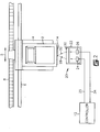
- a replaceable cartridge 2 containing ink is attached to a movable carriage 4 so that, when the printer is in operation, the carriage moves the cartridge in a lateral direction indicated by the arrow 5.
- the carriage 4 is supported and guided by a pair of rails 6 and 6' on which the carriage 4 is free to slide.
- a belt 8 is fixedly attached to the carriage 4 and provides a motive force which causes the carriage 4 to move linearly along the rails 6 and 6'.
- the rails 6 and 6' and belt 8 constitute a preferred embodiment of carriage translation means for moving the carriage 4 in the direction indicated by the arrow 5.
- the carriage 4 is moved laterally across a print medium, such as paper, as ink is ejected from the cartridge 2 through a printhead 10 onto the print medium.
- the printhead 10 which is shown as an integral part of the cartridge 2, contains a plurality of ink ejection nozzles and an ink ejection device for forcing ink from the printhead 10 onto the print medium.
- the printhead 10 generally extends below the carriage 4 when the cartridge 2 is mounted in the carriage 4.
- a printer controller 12 electrically connected to the cartridge 2 by a flexible cable and a connection device, controls the ejection of the ink from individual nozzles on the printhead 10 so that the ink impacts on the print medium in a specific sequence to produce an image as the printer cartridge 4 moves across the print medium in the direction indicated by the arrow 5.
- the printer controller 12 also causes the print medium to move through the printer as the printhead 10 moves orthogonally to the direction of movement of the print medium.
- a label 14 containing indicia is affixed to a surface of the cartridge 2.
- the label 14 is formed from a material such as paper or plastic, and has an adhesive material on one surface for fixedly attaching the label to the cartridge 2.
- the opposing surface of the label 14 contains optically readable indicia 16 which comprises optically-reflective and optically-nonreflective images which provide encoded information identifying the type of cartridge 2 to which the label 14 is affixed.
- the indicia 16 is preferably in the form of bar code characters 18 which are printed across the surface of the label 14.
- the optically readable indicia 16 is printed directly on the cartridge 2 rather than on a label 14.
- the indicia 16 may be applied to the cartridge 2 by a process such as screen printing.
- the color of the cartridge body 2 in the area of the label must be sufficient to provide an optically identifiable contrast between the indicia 16 and the surface 19 of the cartridge 2.
- Fig. 2 is a top plan view of the printer showing the relative positions of the cartridge 2, carriage 4, rails 6, and belt 8. Also illustrated in Fig. 2 is an optical code reader 20 which remains relatively stationary during the printing operation.
- a preferred optical code reader 20 is a reflective sensor available from Hewlett Packard Company of Palo Alto, California under the product code HBCS-1100.
- a typical optical code reader 20 includes a housing 22 containing an emitter 24 and a detector 26 therein which cooperate to produce an electrical signal responsive to the optically-readable indicia 16 on the label 14.
- the optical code reader 20 is positioned such that the label 14 on the cartridge 2 passes proximate to without contacting the optical code reader 20 as the carriage 4 moves linearly along the rails 6.
- the emitter 24 of the optical code reader 20 is a light emitting diode which emits a first light signal 28 at a wavelength of about 700 nanometers responsive to an electrical input signal from the controller 12 on the electrical conduit 25.
- the first light signal 28 passes through a lens 30 which is also contained within or attached to the housing 22.
- the lens 30 is preferably a bifurcated aspheric lens which focuses the first light signal 28 to produce a spot which is about 0.190 millimeters in diameter and which is focused at a point which is about 4.3 millimeters forward of the lens 30.
- characters 18 on the label 14 are comprised of optically reflective and non-reflective images.
- the characters 18 move through the focal point of the first light signal 28 and either reflect or absorb the first light signal 28.
- the non-reflective portions of the label 14 reflect a relatively insignificant amount of the first light signal 28, whereas the reflective portions of the label 14 reflect a significant portion of the first light signal 28 back toward the optical code reader 20.
- the reflected portions of the first light signal 28 constitute a second light signal 32.
- the second light signal 32 produced as the cartridge 2 and label 14 move past the code reader 20, is provided as a series of light pulses caused by reflection and absorption of portions of the first light signal 28.
- the second light signal 32 also passes through the lens 30 and is intercepted by the detector 26.
- the detector 26 is preferably a photodiode matched to receive a light signal from the emitter 24.
- the detector 26 converts the second light signal 32 into an electrical output signal.
- the electrical signal which contains the printer cartridge identification information, is conducted to the printer controller 12 through an electrical conduit 34.
- cartridge identification information is transmitted to the printer controller 12 responsive to the characters 18 on the label 14.
- the printer controller 12 causes the carriage 4 to move the cartridge 2 past the code reader 20.
- the code reader 20 reads the characters 18 on the label 14 and transmits an electrical output signal responsive to the characters to the printer controller 12.
- the printer controller 12 adjusts or controls the printer for proper operation with the installed cartridge 2 in response to the encoded information on the cartridge 2. The printer adjustments can thus be made automatically without user input.
- the invention is also applicable to the identification of any type of interchangeable or replaceable accessory cartridge which may be installed in a printer.
- the invention also provides for the identification of a cartridge containing an image-scanning or image-reading device which may be installed in place of, or in addition to, a print cartridge.
- the invention provides for the identification of an ink cartridge which may be provided as a replaceable cartridge which is separate from the printhead.
- the invention is not limited to the identification of a single cartridge installed in the printer.
- the invention is also applicable to supplying information to a printer controller to identify two or more cartridges installed simultaneously in the same carriage 40 as shown in Fig. 3.
- print cartridges 42 and 44 containing ink and having printheads may be installed in two locations of a multi-station carriage 40, while a scanner cartridge 46 containing an image-scanning device may be installed at another location in the same carriage 40.
- a print cartridge and a scanner cartridge could be attached to independent carriages attached to the rails 6 and belt 8 within the same printer.
- the carriage(s) cause the cartridges and indicia devices 48, 50 and 52 on each cartridge to move past the code reader 54.
- Each indicia device 48, 50 or 52 contains characters which identify the beginning and ending of each encoded sequence.
- the carriage may also contain an encoded indicia device identifying the number of cartridge stations present on the carriage so that the controller can determine how many indicia devices to read.
- a carriage 40 contains a first cartridge 42, a second cartridge 44 and a third cartridge 46.
- Each cartridge preferably contains a different color of ink.
- Each ink cartridge may contain its own printhead or be attached to a printhead body which channels ink from each cartridge to selected locations on the printhead for each color.
- Exemplary ink colors for the cartridges are cyan, magenta and yellow.
- a fourth ink cartridge (not shown) for black ink may also be employed.
- the code reader 54 is preferably substantially centrally located with respect to the carriage travel distance along the support rails 60 so that all encoded information on the cartridges and/or carriages can pass adjacent to the code reader 54.
- replacing a cartridge or powering up the printer causes the carriage(s) to move a sufficient distance in the direction indicated by arrow 5 so that the indicia device(s) passes proximate to the code reader 54 so that the code reader can read the encoded information.
- the electrical output signal to the printer controller may be used in conjunction with a printer control algorithm to change the operating temperature or firing parameters of the heaters on the printhead in response to the type or color of ink contained in the cartridge.
- the printer algorithm may also indicate the location of an ink cartridge of one color with respect to adjacent cartridges of different color. If an ink cartridge of a particular color is installed in an improper location in the carriage, an algorithm in the printer controller may be used to lockout the printer and notify the user of the incorrect cartridge location or otherwise adjust the printhead operation to correspond to the operating parameters required by a particular ink color.
Landscapes
- Physics & Mathematics (AREA)
- Optics & Photonics (AREA)
- Health & Medical Sciences (AREA)
- General Health & Medical Sciences (AREA)
- Toxicology (AREA)
- Ink Jet (AREA)
- Accessory Devices And Overall Control Thereof (AREA)
Abstract
Description
- The present invention relates to printer cartridge identification, and more particularly to apparatus for supplying electrical information to a printer controller of a printer based on the identity of a replaceable accessory cartridge installed in the printer.
- Thermal ink jet printers apply ink to a print medium by ejecting small droplets of ink from an array of nozzles located in the printhead of a print cartridge. An array of thin-film resistors on an integrated circuit on the printhead selectively generates heat as current is passed through the resistors. The heat causes ink contained within an ink reservoir adjacent to the resistors to boil and be ejected from the array of nozzles associated with the resistor array. A printer controller determines which resistors will be "fired" and the proper firing sequence so that the desired pattern of dots is printed on the medium to form an image.
- Conventional ink jet printers accommodate replaceable print cartridges containing either multiple colors of ink or a single color of ink. When the print cartridge is changed, information identifying the type of cartridge installed must be given to the printer so that the printer will function properly with the cartridge. User intervention is conventionally used to identify to the printer controller the type of cartridge installed.
- In order to reduce the cost and complexity of print cartridge manufacturing processes, it is desirable for all cartridges used with a printer to be constructed with a similar configuration regardless of the type of cartridge or color of ink the cartridge contains. Thus it is desirable to maintain substantial overall uniformity of the cartridge shapes and sizes so that a single cartridge design can be used for multiple purposes. However, maintaining a uniform cartridge design makes it more difficult to easily identify the contents of the cartridge or the particular cartridge being used.
- According to one aspect, the invention provides an apparatus for supplying electrical information to a printer controller of a printer based on the identity of a replaceable accessory cartridge installed in the printer. The apparatus comprises a carriage which is laterally translatable relative to the movement of print media through the printer, a carriage translation means, a replaceable accessory cartridge removably attached to the carriage, the accessory cartridge selected from the group consisting of ink cartridges and scanner cartridges, at least one indicia device on the cartridge, the indicia device containing encoded information which identifies to the controller the accessory cartridge installed in the printer, the indicia device comprising optically-reflective images and optically-nonreflective images for reflecting or adsorbing of a first light signal, the reflected portions of the first light signal constituting a second light signal and a light signal reading device for reading the information encoded on the indicia device as the cartridge moves in a lateral direction relative to the reading device, the reading device producing an electrical output signal to the printer controller in response to reflected and/or absorbed light signals wherein the reading device comprises a light-emitting diode for emitting the first light signal toward the indicia device to illuminate the indicia device, at least one lens for focusing the first light signal onto the indicia device as the indicia device translates laterally in relation to the light signal reading device and a detector for receiving the second light signal reflected from the indicia device, and for producing the electrical output signal to the printer controller.
- In another aspect, the invention provides a printer which includes an apparatus for controlling printer operation based on the identity of replaceable ink cartridges in a carriage for the ink. The apparatus comprises a carriage which is laterally translatable relative to the movement of print media through the printer and which contains two, three or four cartridge locations, a carriage translation means, two, three or four replaceable ink cartridges containing ink reservoirs and printheads removably attached to the carriage, at least one indicia device on the cartridge, the indicia device containing encoded information which identifies to the controller which ink reservoir is installed in which cartridge location of the carriage, the indicia device comprising optically-reflective images and optically-nonreflective images for reflecting or adsorbing of a first light signal, the reflected portions of the first light signal constituting a second light signal and a light signal reading device for reading the information encoded on the indicia device as the cartridges move in a lateral direction relative to the reading device, the reading device producing an electrical output signal to the printer controller in response to reflected and/or absorbed light signals wherein the reading device comprises a light-emitting diode for emitting the first light signal toward the indicia device to illuminate the indicia device, at least one lens for focusing the first light signal onto the indicia device as the indicia device translates laterally in relation to the light signal reading device and a detector for receiving the second light signal reflected from the indicia device, and for producing the electrical output signal to the printer controller.
- Thus, at least in its preferred aspects, the invention provides a relatively simple and inexpensive apparatus for encoding information on a replaceable print cartridge.
- Cartridge-specific information, such as ink color and type of cartridge, is provided directly on the cartridge in a manner that is detectable by the printer controller so that the controller may be automatically adjusted without the need for user intervention.
- In addition, the invention provides a cartridge encoding system which can be configured for a wide variety of cartridge types.
- The invention uses the linear motion of the carriage in combination with an optically readable indicia device on the cartridge to identify the type of cartridge, or to otherwise control various printer functions, depending on the specifically encoded information and the location of the cartridge in the carriage. As the carriage containing the cartridge moves relative to substantially fixed code reader, information is extracted from the indicia device and translated into an electrical signal. For example, an ink jet print cartridge moves laterally relative to the movement of the print medium as the printhead ejects ink onto the medium to form printed characters. As the cartridge moves across the print medium, there is movement of the encoded indicia relative to the position of the code reader which remains relatively stationary during the printing operation.
- For the purpose of simplifying the description, the invention is described in terms of a print cartridge which is attached to a carriage of a printer. However, the indicia device may be attached to a movable cartridge used to scan printed pages in order to translate a scanned image into a digital image, or to "read" or translate magnetic data or indicia on a medium into a digital input for a computer. Other types of cartridges or combinations of cartridges may be used with the carriage, indicia device, and code reader according to the invention.
- An advantage of the indicia device and code reader according to the invention is that cartridge identification information may be easily applied to the cartridge at any point in the manufacturing process. Furthermore, the indicia device applied to the cartridge may be encoded for a wide variety of cartridge types, may be used to control various printer functions, and does not require physical connection between the encoded indicia and the code reader.
- Other aspects and advantages of the invention are provided by the following detailed description of preferred embodiments, given by way of example only, considered in conjunction with the following drawings, in which like reference numerals denote like elements throughout the several views, and wherein:
- Fig. 1 is a perspective view, not to scale, of a carriage and cartridge containing optical indicia according to the invention;
- Fig. 2 is a top plan view, not to scale, of a portion of a printer showing a print cartridge, carriage, and optical code reader according to the invention; and
- Fig. 3 is a top plan view, not to scale, of a portion of a printer showing a carriage containing multiple cartridges, and optical code reader according to the invention.
-
- With reference to Figs. 1 and 2, a
replaceable cartridge 2 containing ink is attached to amovable carriage 4 so that, when the printer is in operation, the carriage moves the cartridge in a lateral direction indicated by thearrow 5. Thecarriage 4 is supported and guided by a pair ofrails 6 and 6' on which thecarriage 4 is free to slide. Abelt 8 is fixedly attached to thecarriage 4 and provides a motive force which causes thecarriage 4 to move linearly along therails 6 and 6'. Therails 6 and 6' andbelt 8 constitute a preferred embodiment of carriage translation means for moving thecarriage 4 in the direction indicated by thearrow 5. During a printing procedure, thecarriage 4 is moved laterally across a print medium, such as paper, as ink is ejected from thecartridge 2 through a printhead 10 onto the print medium. - The printhead 10, which is shown as an integral part of the
cartridge 2, contains a plurality of ink ejection nozzles and an ink ejection device for forcing ink from the printhead 10 onto the print medium. The printhead 10 generally extends below thecarriage 4 when thecartridge 2 is mounted in thecarriage 4. Aprinter controller 12, electrically connected to thecartridge 2 by a flexible cable and a connection device, controls the ejection of the ink from individual nozzles on the printhead 10 so that the ink impacts on the print medium in a specific sequence to produce an image as theprinter cartridge 4 moves across the print medium in the direction indicated by thearrow 5. Theprinter controller 12 also causes the print medium to move through the printer as the printhead 10 moves orthogonally to the direction of movement of the print medium. - With continued reference to Fig. 1, a label 14 containing indicia is affixed to a surface of the
cartridge 2. Preferably, the label 14 is formed from a material such as paper or plastic, and has an adhesive material on one surface for fixedly attaching the label to thecartridge 2. The opposing surface of the label 14 contains optically readable indicia 16 which comprises optically-reflective and optically-nonreflective images which provide encoded information identifying the type ofcartridge 2 to which the label 14 is affixed. The indicia 16 is preferably in the form of bar code characters 18 which are printed across the surface of the label 14. - In an alternative embodiment, the optically readable indicia 16 is printed directly on the
cartridge 2 rather than on a label 14. The indicia 16 may be applied to thecartridge 2 by a process such as screen printing. In such case, the color of thecartridge body 2 in the area of the label must be sufficient to provide an optically identifiable contrast between the indicia 16 and thesurface 19 of thecartridge 2. - Fig. 2 is a top plan view of the printer showing the relative positions of the
cartridge 2,carriage 4,rails 6, andbelt 8. Also illustrated in Fig. 2 is anoptical code reader 20 which remains relatively stationary during the printing operation. A preferredoptical code reader 20 is a reflective sensor available from Hewlett Packard Company of Palo Alto, California under the product code HBCS-1100. A typicaloptical code reader 20 includes ahousing 22 containing anemitter 24 and adetector 26 therein which cooperate to produce an electrical signal responsive to the optically-readable indicia 16 on the label 14. Theoptical code reader 20 is positioned such that the label 14 on thecartridge 2 passes proximate to without contacting theoptical code reader 20 as thecarriage 4 moves linearly along therails 6. - In a preferred embodiment, the
emitter 24 of theoptical code reader 20 is a light emitting diode which emits a first light signal 28 at a wavelength of about 700 nanometers responsive to an electrical input signal from thecontroller 12 on theelectrical conduit 25. The first light signal 28 passes through alens 30 which is also contained within or attached to thehousing 22. Thelens 30 is preferably a bifurcated aspheric lens which focuses the first light signal 28 to produce a spot which is about 0.190 millimeters in diameter and which is focused at a point which is about 4.3 millimeters forward of thelens 30. - As described above, characters 18 on the label 14 are comprised of optically reflective and non-reflective images. As the
cartridge 2 moves past theoptical code reader 20, the characters 18 move through the focal point of the first light signal 28 and either reflect or absorb the first light signal 28. The non-reflective portions of the label 14 reflect a relatively insignificant amount of the first light signal 28, whereas the reflective portions of the label 14 reflect a significant portion of the first light signal 28 back toward theoptical code reader 20. The reflected portions of the first light signal 28 constitute a second light signal 32. When the indicia 16 is in the form of a bar code, the second light signal 32, produced as thecartridge 2 and label 14 move past thecode reader 20, is provided as a series of light pulses caused by reflection and absorption of portions of the first light signal 28. - With continued reference to Fig. 2, the second light signal 32 also passes through the
lens 30 and is intercepted by thedetector 26. Thedetector 26 is preferably a photodiode matched to receive a light signal from theemitter 24. Thedetector 26 converts the second light signal 32 into an electrical output signal. The electrical signal, which contains the printer cartridge identification information, is conducted to theprinter controller 12 through anelectrical conduit 34. - When the printer is in operation, cartridge identification information is transmitted to the
printer controller 12 responsive to the characters 18 on the label 14. When the printer power is first turned on, or when thecartridge 2 is removed or replaced, theprinter controller 12 causes thecarriage 4 to move thecartridge 2 past thecode reader 20. As thecartridge 2 moves relative to thecode reader 20, thecode reader 20 reads the characters 18 on the label 14 and transmits an electrical output signal responsive to the characters to theprinter controller 12. Theprinter controller 12 adjusts or controls the printer for proper operation with the installedcartridge 2 in response to the encoded information on thecartridge 2. The printer adjustments can thus be made automatically without user input. - Since the scope of the invention is not limited to the identification of print cartridges only, it will be appreciated that the invention is also applicable to the identification of any type of interchangeable or replaceable accessory cartridge which may be installed in a printer. For example, the invention also provides for the identification of a cartridge containing an image-scanning or image-reading device which may be installed in place of, or in addition to, a print cartridge. Furthermore, the invention provides for the identification of an ink cartridge which may be provided as a replaceable cartridge which is separate from the printhead.
- It will also be appreciated that the invention is not limited to the identification of a single cartridge installed in the printer. The invention is also applicable to supplying information to a printer controller to identify two or more cartridges installed simultaneously in the
same carriage 40 as shown in Fig. 3. For example,print cartridges multi-station carriage 40, while ascanner cartridge 46 containing an image-scanning device may be installed at another location in thesame carriage 40. Alternatively, a print cartridge and a scanner cartridge could be attached to independent carriages attached to therails 6 andbelt 8 within the same printer. Regardless of whether one or more carriages are used, the carriage(s) cause the cartridges andindicia devices code reader 54. Eachindicia device - With reference to Figure 3, in a three cartridge embodiment, for example, a
carriage 40 contains afirst cartridge 42, asecond cartridge 44 and athird cartridge 46. Each cartridge preferably contains a different color of ink. Each ink cartridge may contain its own printhead or be attached to a printhead body which channels ink from each cartridge to selected locations on the printhead for each color. Exemplary ink colors for the cartridges are cyan, magenta and yellow. Optionally, a fourth ink cartridge (not shown) for black ink may also be employed. - In the case of multiple carriages, or multiple cartridge positions on a single carriage, the
code reader 54 is preferably substantially centrally located with respect to the carriage travel distance along the support rails 60 so that all encoded information on the cartridges and/or carriages can pass adjacent to thecode reader 54. As in the previous embodiment, replacing a cartridge or powering up the printer causes the carriage(s) to move a sufficient distance in the direction indicated byarrow 5 so that the indicia device(s) passes proximate to thecode reader 54 so that the code reader can read the encoded information. - The electrical output signal to the printer controller may be used in conjunction with a printer control algorithm to change the operating temperature or firing parameters of the heaters on the printhead in response to the type or color of ink contained in the cartridge. In the case of multiple cartridges containing different color inks, the printer algorithm may also indicate the location of an ink cartridge of one color with respect to adjacent cartridges of different color. If an ink cartridge of a particular color is installed in an improper location in the carriage, an algorithm in the printer controller may be used to lockout the printer and notify the user of the incorrect cartridge location or otherwise adjust the printhead operation to correspond to the operating parameters required by a particular ink color.
- It is contemplated, and will be apparent to those skilled in the art from the preceding description and the accompanying drawings that modifications and additions may be made to the invention. Accordingly, it is expressly intended that the foregoing description and the accompanying drawings are illustrative of preferred embodiments only, and that the scope of the invention be determined by the appended claims.
Claims (13)
- An apparatus for supplying electrical information to a printer controller of a printer based on the identity of a replaceable accessory cartridge installed in the printer, the apparatus comprising:a carriage which is laterally translatable relative to the movement of print media through the printer;carriage translation means;a replaceable accessory cartridge removably attached to the carriage, the accessory cartridge selected from the group consisting of ink cartridges and scanner cartridges;at least one indicia device on the cartridge, the indicia device containing encoded information which identifies to the controller the accessory cartridge installed in the printer, the indicia device comprising optically-reflective images and optically-nonreflective images for reflecting or adsorbing of a first light signal, the reflected portions of the first light signal constituting a second light signal; anda light signal reading device for reading the information encoded on the indicia device as the cartridge moves in a lateral direction relative to the reading device, the reading device producing an electrical output signal to the printer controller in response to reflected and/or absorbed light signals wherein the reading device comprises a light-emitting diode for emitting the first light signal toward the indicia device to illuminate the indicia device, at least one lens for focusing the first light signal onto the indicia device as the indicia device translates laterally in relation to the light signal reading device and a detector for receiving the second light signal reflected from the indicia device, and for producing the electrical output signal to the printer controller.
- The apparatus of Claim 1 further comprising two, three or four accessory cartridges removably attached to the carrier each cartridge containing an indicia device attached thereto.
- The apparatus of Claim 2 wherein the accessory cartridges comprise ink cartridges.
- An apparatus for controlling printer operation based on the identity of replaceable ink cartridges in a carriage for the ink which comprises:a carriage which is laterally translatable relative to the movement of print media through the printer and which contains two, three or four cartridge locations;carriage translation means;two, three or four replaceable ink cartridges containing ink reservoirs and printheads removably attached to the carriage;at least one indicia device on the cartridge, the indicia device containing encoded information which identifies to a printer controller which ink reservoir is installed in which cartridge location of the, the indicia device comprising optically-reflective images and optically-nonreflective images for reflecting or adsorbing of a first light signal, the reflected portions of the first light signal constituting a second light signal; anda light signal reading device for reading the information encoded on the indicia device as the cartridges move in a lateral direction relative to the reading device, the reading device producing an electrical output signal to the printer controller in response to reflected and/or absorbed light signals wherein the reading device comprises a light-emitting diode for emitting the first light signal toward the indicia device to illuminate the indicia device, at least one lens for focusing the first light signal onto the indicia device as the indicia device translates laterally in relation to the light signal reading device and a detector for receiving the second light signal reflected from the indicia device, and for producing the electrical output signal to the printer controller.
- The apparatus of Claim 3 or 4 further comprising a printer control algorithm responsive to the electrical output signal from the reading device for locking out printer operation for one or more incorrect ink cartridge locations.
- The apparatus of Claim 3 or 4 further comprising a printer control algorithm responsive to the electrical output signal from the reading device for changing an operating temperature of the printheads for the installed cartridges.
- The apparatus of Claim 3 or 4 further comprising a printer control algorithm responsive to the electrical output signal from the reading device for changing firing parameters for heaters on the printheads for the installed cartridges.
- The apparatus of any of Claims 3 to 7 wherein the ink cartridges comprise a yellow ink cartridge, a cyan ink cartridge and a magenta ink cartridge.
- The apparatus of any preceding Claim wherein the indicia device comprises a planar label having optically reflective and non-reflective images on one surface thereof and an adhesive material on an opposing surface thereof for fixed attaching the label to the accessory cartridge.
- The apparatus of any preceding Claim wherein the first light signal has a wavelength of about 700 nanometers.
- An ink jet printer cartridge containing an ink reservoir, the cartridge being provided with optically-reflective indicia means containing encoded information relating to the type of printer cartridge, the indicia means being configured to be readable by an optical reader on movement of the cartridge relative to the reader.
- A scanner cartridge provided with optically-reflective indicia means containing encoded information relating to the type of scanner cartridge, the indicia means being configured to be readable by an optical reader on movement of the cartridge relative to the reader.
- A printer comprising a printer controller, a replaceable accessory cartridge provided with optically-reflective indicia means containing encoded information relating to the type of cartridge, and means for reading the encoded information which, on movement of the cartridge relative to the means for reading, produces an electrical output signal to the printer controller in dependence on the encoded information.
Applications Claiming Priority (2)
| Application Number | Priority Date | Filing Date | Title |
|---|---|---|---|
| US08/990,608 US6299274B1 (en) | 1997-12-15 | 1997-12-15 | Thermal ink jet printer cartridge identification |
| US990608 | 1997-12-15 |
Publications (3)
| Publication Number | Publication Date |
|---|---|
| EP0925936A2 true EP0925936A2 (en) | 1999-06-30 |
| EP0925936A3 EP0925936A3 (en) | 2000-01-12 |
| EP0925936B1 EP0925936B1 (en) | 2005-09-07 |
Family
ID=25536327
Family Applications (1)
| Application Number | Title | Priority Date | Filing Date |
|---|---|---|---|
| EP98310283A Expired - Lifetime EP0925936B1 (en) | 1997-12-15 | 1998-12-15 | Printer cartridge identification |
Country Status (5)
| Country | Link |
|---|---|
| US (1) | US6299274B1 (en) |
| EP (1) | EP0925936B1 (en) |
| JP (1) | JPH11263025A (en) |
| KR (1) | KR19990063071A (en) |
| DE (1) | DE69831469T2 (en) |
Cited By (7)
| Publication number | Priority date | Publication date | Assignee | Title |
|---|---|---|---|---|
| WO2001017784A1 (en) * | 1999-09-06 | 2001-03-15 | Inksure Ltd. | Genuine printing refill and method |
| EP1153752A3 (en) * | 2000-04-14 | 2003-08-20 | Canon Kabushiki Kaisha | Semiconductor device, ink tank provided with such device and method of manufacturing such device |
| EP1439068A2 (en) * | 2003-01-15 | 2004-07-21 | Xerox Corporation | Custom color inkjet printing system |
| US6978255B1 (en) * | 1999-11-26 | 2005-12-20 | Francotyp-Postalia Ag & Co. | Method for protecting a device against operation with unallowed consumables and arrangement for the implementation of the method |
| US7102647B2 (en) | 2001-06-26 | 2006-09-05 | Microsoft Corporation | Interactive horizon mapping |
| AU2002237968B2 (en) * | 2001-01-31 | 2007-06-07 | Hewlett-Packard Development Company, L.P. | Method and apparatus for product regionalization |
| EP3433075A4 (en) * | 2016-07-22 | 2019-12-18 | Hewlett-Packard Development Company, L.P. | Container for an additive manufacturing system |
Families Citing this family (22)
| Publication number | Priority date | Publication date | Assignee | Title |
|---|---|---|---|---|
| US6724895B1 (en) | 1998-06-18 | 2004-04-20 | Supersensor (Proprietary) Limited | Electronic identification system and method with source authenticity verification |
| WO2002040275A1 (en) * | 2000-11-20 | 2002-05-23 | Seiko Epson Corporation | Identification of container for printing recording material |
| CN2592384Y (en) * | 2001-11-08 | 2003-12-17 | 精工爱普生株式会社 | Ink cartridge and recording apparatus |
| KR20030091373A (en) * | 2002-05-27 | 2003-12-03 | 삼성전자주식회사 | Cartridge identification apparatus |
| US20040066435A1 (en) * | 2002-10-08 | 2004-04-08 | Lester Samuel M. | Method and means for configuring a printer |
| US6827420B2 (en) | 2002-12-18 | 2004-12-07 | Lexmark International, Inc. | Device verification using printed patterns and optical sensing |
| KR100485792B1 (en) * | 2002-12-30 | 2005-04-28 | 삼성전자주식회사 | Sheet inserting limit apparatus for sheet feeding unit |
| US7589850B2 (en) * | 2002-12-30 | 2009-09-15 | Lexmark International, Inc. | Licensing method for use with an imaging device |
| US7240995B2 (en) * | 2003-05-06 | 2007-07-10 | Lexmark International, Inc. | Method of authenticating a consumable |
| US7360858B2 (en) * | 2003-06-30 | 2008-04-22 | Brother Kogyo Kabushiki Kaisha | Ink cartridge, detection device for cartridge identification and ink level detection, and image formation apparatus comprising thereof |
| US7299984B2 (en) * | 2003-08-21 | 2007-11-27 | Pitney Bowes Inc. | Postage indicia including encoded ink characteristic data |
| MXPA04012681A (en) | 2003-12-26 | 2005-07-01 | Canon Kk | Liquid container and liquid supplying system. |
| KR20050082464A (en) * | 2004-02-19 | 2005-08-24 | 삼성전자주식회사 | Apparatus for spraying organic material on the substrate |
| US8099791B1 (en) | 2004-06-25 | 2012-01-17 | Lexmark International, Inc. | Method of authenticating a consumable in an imaging device |
| US20060190324A1 (en) * | 2005-02-24 | 2006-08-24 | Lexmark International, Inc. | Method for providing reduced cost imaging to customers |
| US20060279127A1 (en) * | 2005-06-09 | 2006-12-14 | Cronin John E | Apparatus including a selective interface system between two sub-components |
| JP4756928B2 (en) * | 2005-06-21 | 2011-08-24 | キヤノン株式会社 | Printer |
| US7604317B2 (en) * | 2005-06-21 | 2009-10-20 | Canon Kabushiki Kaisha | Recording apparatus capable of checking positions of ink containers, and method for checking the positions |
| KR100717038B1 (en) * | 2005-10-10 | 2007-05-10 | 삼성전자주식회사 | Measurement device of a property of ink, inkjet printer icluding thereof, and method for sensing ink-condition |
| DE102009026107A1 (en) * | 2009-07-06 | 2011-01-13 | Pelikan Hardcopy Production Ag | Ink cartridge and ink jet printer for receiving such an ink cartridge |
| US9964891B2 (en) * | 2014-12-17 | 2018-05-08 | Lexmark International, Inc. | Systems for optical communication between an image forming device and a replaceable unit of the image forming device |
| CN113524913B (en) * | 2020-04-18 | 2022-10-21 | 深圳市汉森软件有限公司 | Ink authorization use method, server, upper computer, printing equipment and system |
Citations (5)
| Publication number | Priority date | Publication date | Assignee | Title |
|---|---|---|---|---|
| US4411540A (en) * | 1980-08-27 | 1983-10-25 | Canon Kabushiki Kaisha | Printing apparatus |
| US4970531A (en) * | 1987-02-13 | 1990-11-13 | Hitachi, Ltd. | Thermal transfer printer |
| JPH05345411A (en) * | 1992-06-15 | 1993-12-27 | Canon Inc | Ink jet recording apparatus |
| EP0720916A2 (en) * | 1995-01-03 | 1996-07-10 | Xerox Corporation | Ink supply identification system for a printer |
| WO1997023352A1 (en) * | 1995-12-25 | 1997-07-03 | Seiko Epson Corporation | Ink-jet recording apparatus for ink cartridge |
Family Cites Families (18)
| Publication number | Priority date | Publication date | Assignee | Title |
|---|---|---|---|---|
| JPS56167484A (en) | 1980-05-30 | 1981-12-23 | Canon Inc | Printer |
| AU530568B2 (en) | 1980-10-31 | 1983-07-21 | Canon Kabushiki Kaisha | Serial printing apparatus with memory and display |
| US4428694A (en) | 1981-02-11 | 1984-01-31 | Xerox Corporation | Rotary printing device with identifying means and method and apparatus for in situ identification |
| JPS58211476A (en) | 1982-06-02 | 1983-12-08 | Canon Inc | Electronic printer |
| US5235351A (en) | 1984-03-31 | 1993-08-10 | Canon Kabushiki Kaisha | Liquid ejection recording head including a symbol indicating information used for changing the operation of the head |
| JPS61137748A (en) | 1984-12-10 | 1986-06-25 | Canon Inc | Apparatus for discriminating type wheel |
| JP2832710B2 (en) | 1987-01-07 | 1998-12-09 | 沖電気工業 株式会社 | Printer |
| US4872027A (en) | 1987-11-03 | 1989-10-03 | Hewlett-Packard Company | Printer having identifiable interchangeable heads |
| US5033887A (en) * | 1988-07-25 | 1991-07-23 | Nixdorf Computer Ag | Process for the production of information relative to the type of a printing head |
| JPH02198881A (en) | 1989-01-27 | 1990-08-07 | Shimadzu Corp | Printer |
| US5049898A (en) | 1989-03-20 | 1991-09-17 | Hewlett-Packard Company | Printhead having memory element |
| DE3914256A1 (en) | 1989-04-29 | 1990-10-31 | Olympia Aeg | METHOD FOR AUTOMATICALLY IDENTIFYING A TYPE WHEEL |
| ES2252908T3 (en) * | 1989-08-05 | 2006-05-16 | Canon Kabushiki Kaisha | PRINTING DEVICE FOR INK JETS AND INK CARTRIDGE FOR THE APPLIANCE. |
| JP2915583B2 (en) | 1991-01-14 | 1999-07-05 | キヤノン株式会社 | Image recording device |
| US5471163A (en) | 1993-11-16 | 1995-11-28 | Hewlett-Packard Company | Tab circuit fusible links for disconnection or encoding information |
| US5488223A (en) | 1994-09-13 | 1996-01-30 | Intermec Corporation | System and method for automatic selection of printer control parameters |
| US5699091A (en) * | 1994-12-22 | 1997-12-16 | Hewlett-Packard Company | Replaceable part with integral memory for usage, calibration and other data |
| US5710418A (en) * | 1995-11-03 | 1998-01-20 | Tawara; Masami | Optical image sensor |
-
1997
- 1997-12-15 US US08/990,608 patent/US6299274B1/en not_active Expired - Lifetime
-
1998
- 1998-12-15 DE DE69831469T patent/DE69831469T2/en not_active Expired - Lifetime
- 1998-12-15 JP JP10356751A patent/JPH11263025A/en not_active Withdrawn
- 1998-12-15 EP EP98310283A patent/EP0925936B1/en not_active Expired - Lifetime
- 1998-12-15 KR KR1019980055108A patent/KR19990063071A/en not_active Application Discontinuation
Patent Citations (5)
| Publication number | Priority date | Publication date | Assignee | Title |
|---|---|---|---|---|
| US4411540A (en) * | 1980-08-27 | 1983-10-25 | Canon Kabushiki Kaisha | Printing apparatus |
| US4970531A (en) * | 1987-02-13 | 1990-11-13 | Hitachi, Ltd. | Thermal transfer printer |
| JPH05345411A (en) * | 1992-06-15 | 1993-12-27 | Canon Inc | Ink jet recording apparatus |
| EP0720916A2 (en) * | 1995-01-03 | 1996-07-10 | Xerox Corporation | Ink supply identification system for a printer |
| WO1997023352A1 (en) * | 1995-12-25 | 1997-07-03 | Seiko Epson Corporation | Ink-jet recording apparatus for ink cartridge |
Non-Patent Citations (1)
| Title |
|---|
| PATENT ABSTRACTS OF JAPAN vol. 018, no. 186 (M-1585), 30 March 1994 (1994-03-30) & JP 05 345411 A (CANON INC), 27 December 1993 (1993-12-27) * |
Cited By (13)
| Publication number | Priority date | Publication date | Assignee | Title |
|---|---|---|---|---|
| WO2001017784A1 (en) * | 1999-09-06 | 2001-03-15 | Inksure Ltd. | Genuine printing refill and method |
| US6978255B1 (en) * | 1999-11-26 | 2005-12-20 | Francotyp-Postalia Ag & Co. | Method for protecting a device against operation with unallowed consumables and arrangement for the implementation of the method |
| EP1153752A3 (en) * | 2000-04-14 | 2003-08-20 | Canon Kabushiki Kaisha | Semiconductor device, ink tank provided with such device and method of manufacturing such device |
| US6719394B2 (en) | 2000-04-14 | 2004-04-13 | Canon Kabushiki Kaisha | Semiconductor device, ink tank provided with such semiconductor device, ink jet cartridge, ink jet recording apparatus, method for manufacturing such semiconductor device, and communication system, method for controlling pressure, memory element, security system of ink jet recording apparatus |
| EP1710085A3 (en) * | 2000-04-14 | 2007-11-28 | Canon Kabushiki Kaisha | Semiconductor device, ink tank provided with such semiconductor device, ink jet cartridge, ink jet recorsding apparatus, method for manufacturing such semiconductor device, and communication system, method for controlling pressure, memory element, security system of ink jet recording apparatus |
| EP1710085A2 (en) * | 2000-04-14 | 2006-10-11 | Canon Kabushiki Kaisha | Semiconductor device, ink tank provided with such semiconductor device, ink jet cartridge, ink jet recorsding apparatus, method for manufacturing such semiconductor device, and communication system, method for controlling pressure, memory element, security system of ink jet recording apparatus |
| AU2002237968B2 (en) * | 2001-01-31 | 2007-06-07 | Hewlett-Packard Development Company, L.P. | Method and apparatus for product regionalization |
| US7102647B2 (en) | 2001-06-26 | 2006-09-05 | Microsoft Corporation | Interactive horizon mapping |
| US6938984B2 (en) | 2003-01-15 | 2005-09-06 | Xerox Corporation | Custom color inkjet printing system |
| EP1439068A3 (en) * | 2003-01-15 | 2004-11-10 | Xerox Corporation | Custom color inkjet printing system |
| EP1439068A2 (en) * | 2003-01-15 | 2004-07-21 | Xerox Corporation | Custom color inkjet printing system |
| EP3433075A4 (en) * | 2016-07-22 | 2019-12-18 | Hewlett-Packard Development Company, L.P. | Container for an additive manufacturing system |
| US11235525B2 (en) | 2016-07-22 | 2022-02-01 | Hewlett-Packard Development Company, L.P. | Container for an additive manufacturing system |
Also Published As
| Publication number | Publication date |
|---|---|
| DE69831469T2 (en) | 2006-07-06 |
| EP0925936A3 (en) | 2000-01-12 |
| US6299274B1 (en) | 2001-10-09 |
| DE69831469D1 (en) | 2005-10-13 |
| JPH11263025A (en) | 1999-09-28 |
| KR19990063071A (en) | 1999-07-26 |
| EP0925936B1 (en) | 2005-09-07 |
Similar Documents
| Publication | Publication Date | Title |
|---|---|---|
| EP0925936B1 (en) | Printer cartridge identification | |
| US6523920B2 (en) | Combination ink jet pen and optical scanner head and methods of improving print quality | |
| US6325505B1 (en) | Media type detection system for inkjet printing | |
| EP0863012B1 (en) | Detection of printhead nozzle functionality by optical scanning of a test pattern | |
| EP0748693B1 (en) | Thermal ink jet printhead with extended print capability | |
| US6322192B1 (en) | Multi-function optical sensing system for inkjet printing | |
| US6325480B1 (en) | Ink jet printer and method capable of forming a plurality of registration marks on a receiver and sensing the marks formed thereby | |
| JP3281520B2 (en) | Recording device | |
| EP0983855A2 (en) | Dot substitution to compensate for failed ink jet nozzles | |
| EP0974468A2 (en) | An adjusting method of dot printing positions and a printing apparatus | |
| EP1010531A1 (en) | Method and apparatus for hiding errors in single-pass incremental printing | |
| JP2009107346A (en) | Printer scanner having print head cap sensor | |
| JP2001063031A (en) | Method and device for aligning transparent liquid ink jet pen | |
| EP0664221B1 (en) | A serial printing apparatus controlled by open loop control system | |
| JPH0876644A (en) | Image recorder | |
| EP1308287B1 (en) | Method and system for callibrating ink ejection elements in an image forming device | |
| US6174046B1 (en) | Reliable contact pad arrangement on plastic print cartridge | |
| US6460962B1 (en) | Ink jet printer with sensing system for identifying various types of printhead cartridges | |
| US7794073B2 (en) | Ink jet printer | |
| JPH01501780A (en) | Collaborative inkjet printing/cartridge orifice spacing system | |
| JP2007152784A (en) | Registering method for ink-jet printer | |
| JPH0419149A (en) | Recording method | |
| JP2001047638A (en) | Multicolor liquid ink printer equipped with system for detecting kind and position of ink | |
| JP3178589B2 (en) | Color recording device | |
| JPH08323991A (en) | Recording device |
Legal Events
| Date | Code | Title | Description |
|---|---|---|---|
| PUAI | Public reference made under article 153(3) epc to a published international application that has entered the european phase |
Free format text: ORIGINAL CODE: 0009012 |
|
| AK | Designated contracting states |
Kind code of ref document: A2 Designated state(s): DE FR GB |
|
| AX | Request for extension of the european patent |
Free format text: AL;LT;LV;MK;RO;SI |
|
| PUAL | Search report despatched |
Free format text: ORIGINAL CODE: 0009013 |
|
| AK | Designated contracting states |
Kind code of ref document: A3 Designated state(s): AT BE CH CY DE DK ES FI FR GB GR IE IT LI LU MC NL PT SE |
|
| AX | Request for extension of the european patent |
Free format text: AL;LT;LV;MK;RO;SI |
|
| 17P | Request for examination filed |
Effective date: 20000706 |
|
| AKX | Designation fees paid |
Free format text: DE FR GB |
|
| 17Q | First examination report despatched |
Effective date: 20040312 |
|
| GRAP | Despatch of communication of intention to grant a patent |
Free format text: ORIGINAL CODE: EPIDOSNIGR1 |
|
| GRAS | Grant fee paid |
Free format text: ORIGINAL CODE: EPIDOSNIGR3 |
|
| GRAA | (expected) grant |
Free format text: ORIGINAL CODE: 0009210 |
|
| AK | Designated contracting states |
Kind code of ref document: B1 Designated state(s): DE FR GB |
|
| REG | Reference to a national code |
Ref country code: GB Ref legal event code: FG4D |
|
| REF | Corresponds to: |
Ref document number: 69831469 Country of ref document: DE Date of ref document: 20051013 Kind code of ref document: P |
|
| ET | Fr: translation filed | ||
| PLBE | No opposition filed within time limit |
Free format text: ORIGINAL CODE: 0009261 |
|
| STAA | Information on the status of an ep patent application or granted ep patent |
Free format text: STATUS: NO OPPOSITION FILED WITHIN TIME LIMIT |
|
| 26N | No opposition filed |
Effective date: 20060608 |
|
| PGFP | Annual fee paid to national office [announced via postgrant information from national office to epo] |
Ref country code: GB Payment date: 20101229 Year of fee payment: 13 |
|
| GBPC | Gb: european patent ceased through non-payment of renewal fee |
Effective date: 20121215 |
|
| PG25 | Lapsed in a contracting state [announced via postgrant information from national office to epo] |
Ref country code: GB Free format text: LAPSE BECAUSE OF NON-PAYMENT OF DUE FEES Effective date: 20121215 |
|
| REG | Reference to a national code |
Ref country code: DE Ref legal event code: R082 Ref document number: 69831469 Country of ref document: DE Representative=s name: ABITZ & PARTNER PATENTANWAELTE MBB, DE Effective date: 20131107 Ref country code: DE Ref legal event code: R082 Ref document number: 69831469 Country of ref document: DE Representative=s name: ABITZ & PARTNER, DE Effective date: 20131107 Ref country code: DE Ref legal event code: R081 Ref document number: 69831469 Country of ref document: DE Owner name: FUNAI ELECTRIC CO., LTD, DAITO CITY, JP Free format text: FORMER OWNER: LEXMARK INTERNATIONAL, INC., LEXINGTON, KY., US Effective date: 20131107 Ref country code: DE Ref legal event code: R081 Ref document number: 69831469 Country of ref document: DE Owner name: FUNAI ELECTRIC CO., LTD, JP Free format text: FORMER OWNER: LEXMARK INTERNATIONAL, INC., LEXINGTON, US Effective date: 20131107 |
|
| REG | Reference to a national code |
Ref country code: FR Ref legal event code: TP Owner name: FUNAI ELECTRIC CO LTD, JP Effective date: 20140102 |
|
| PGFP | Annual fee paid to national office [announced via postgrant information from national office to epo] |
Ref country code: DE Payment date: 20141209 Year of fee payment: 17 |
|
| PGFP | Annual fee paid to national office [announced via postgrant information from national office to epo] |
Ref country code: FR Payment date: 20141208 Year of fee payment: 17 |
|
| REG | Reference to a national code |
Ref country code: DE Ref legal event code: R119 Ref document number: 69831469 Country of ref document: DE |
|
| REG | Reference to a national code |
Ref country code: FR Ref legal event code: ST Effective date: 20160831 |
|
| PG25 | Lapsed in a contracting state [announced via postgrant information from national office to epo] |
Ref country code: DE Free format text: LAPSE BECAUSE OF NON-PAYMENT OF DUE FEES Effective date: 20160701 |
|
| PG25 | Lapsed in a contracting state [announced via postgrant information from national office to epo] |
Ref country code: FR Free format text: LAPSE BECAUSE OF NON-PAYMENT OF DUE FEES Effective date: 20151231 |