EP0925916A1 - A heat sensitive non-ablatable wasteless imaging element for providing a lithographic printing plate with a difference in dye density between the image and non image areas - Google Patents
A heat sensitive non-ablatable wasteless imaging element for providing a lithographic printing plate with a difference in dye density between the image and non image areas Download PDFInfo
- Publication number
- EP0925916A1 EP0925916A1 EP98203792A EP98203792A EP0925916A1 EP 0925916 A1 EP0925916 A1 EP 0925916A1 EP 98203792 A EP98203792 A EP 98203792A EP 98203792 A EP98203792 A EP 98203792A EP 0925916 A1 EP0925916 A1 EP 0925916A1
- Authority
- EP
- European Patent Office
- Prior art keywords
- imaging element
- lithographic printing
- image
- printing plates
- layer
- Prior art date
- Legal status (The legal status is an assumption and is not a legal conclusion. Google has not performed a legal analysis and makes no representation as to the accuracy of the status listed.)
- Granted
Links
- 238000003384 imaging method Methods 0.000 title claims abstract description 56
- 230000002209 hydrophobic effect Effects 0.000 claims abstract description 15
- 230000003287 optical effect Effects 0.000 claims abstract description 3
- 239000002245 particle Substances 0.000 claims description 27
- 229920000642 polymer Polymers 0.000 claims description 12
- 150000001875 compounds Chemical class 0.000 claims description 11
- 229920002451 polyvinyl alcohol Polymers 0.000 claims description 11
- 235000019422 polyvinyl alcohol Nutrition 0.000 claims description 11
- 239000004372 Polyvinyl alcohol Substances 0.000 claims description 10
- 239000011230 binding agent Substances 0.000 claims description 8
- 239000002253 acid Substances 0.000 claims description 7
- RKJUIXBNRJVNHR-UHFFFAOYSA-N indolenine group Chemical group N1=CCC2=CC=CC=C12 RKJUIXBNRJVNHR-UHFFFAOYSA-N 0.000 claims description 5
- 239000003431 cross linking reagent Substances 0.000 claims description 4
- ANRHNWWPFJCPAZ-UHFFFAOYSA-M thionine Chemical compound [Cl-].C1=CC(N)=CC2=[S+]C3=CC(N)=CC=C3N=C21 ANRHNWWPFJCPAZ-UHFFFAOYSA-M 0.000 claims description 3
- 239000010410 layer Substances 0.000 description 59
- 239000000975 dye Substances 0.000 description 22
- 239000006185 dispersion Substances 0.000 description 17
- 238000000576 coating method Methods 0.000 description 16
- 238000000034 method Methods 0.000 description 16
- 239000011248 coating agent Substances 0.000 description 14
- VYPSYNLAJGMNEJ-UHFFFAOYSA-N Silicium dioxide Chemical compound O=[Si]=O VYPSYNLAJGMNEJ-UHFFFAOYSA-N 0.000 description 12
- -1 silver halide Chemical class 0.000 description 10
- 229920001169 thermoplastic Polymers 0.000 description 10
- XLYOFNOQVPJJNP-UHFFFAOYSA-N water Substances O XLYOFNOQVPJJNP-UHFFFAOYSA-N 0.000 description 9
- GWEVSGVZZGPLCZ-UHFFFAOYSA-N Titan oxide Chemical compound O=[Ti]=O GWEVSGVZZGPLCZ-UHFFFAOYSA-N 0.000 description 8
- 239000000243 solution Substances 0.000 description 8
- 229910052782 aluminium Inorganic materials 0.000 description 7
- XAGFODPZIPBFFR-UHFFFAOYSA-N aluminium Chemical compound [Al] XAGFODPZIPBFFR-UHFFFAOYSA-N 0.000 description 7
- 239000008119 colloidal silica Substances 0.000 description 6
- 229920001577 copolymer Polymers 0.000 description 6
- 239000000203 mixture Substances 0.000 description 6
- 229910052709 silver Inorganic materials 0.000 description 6
- 239000004332 silver Substances 0.000 description 6
- 238000011282 treatment Methods 0.000 description 6
- 239000004793 Polystyrene Substances 0.000 description 5
- 229940024548 aluminum oxide Drugs 0.000 description 5
- 230000015271 coagulation Effects 0.000 description 5
- 238000005345 coagulation Methods 0.000 description 5
- 239000000463 material Substances 0.000 description 5
- TWNQGVIAIRXVLR-UHFFFAOYSA-N oxo(oxoalumanyloxy)alumane Chemical compound O=[Al]O[Al]=O TWNQGVIAIRXVLR-UHFFFAOYSA-N 0.000 description 5
- 229920002223 polystyrene Polymers 0.000 description 5
- 239000011888 foil Substances 0.000 description 4
- 239000000976 ink Substances 0.000 description 4
- 239000007788 liquid Substances 0.000 description 4
- 229910052751 metal Inorganic materials 0.000 description 4
- 239000002184 metal Substances 0.000 description 4
- 239000000126 substance Substances 0.000 description 4
- LFQCEHFDDXELDD-UHFFFAOYSA-N tetramethyl orthosilicate Chemical compound CO[Si](OC)(OC)OC LFQCEHFDDXELDD-UHFFFAOYSA-N 0.000 description 4
- BQCADISMDOOEFD-UHFFFAOYSA-N Silver Chemical compound [Ag] BQCADISMDOOEFD-UHFFFAOYSA-N 0.000 description 3
- 239000006229 carbon black Substances 0.000 description 3
- KRKNYBCHXYNGOX-UHFFFAOYSA-N citric acid Chemical compound OC(=O)CC(O)(C(O)=O)CC(O)=O KRKNYBCHXYNGOX-UHFFFAOYSA-N 0.000 description 3
- 229920001600 hydrophobic polymer Polymers 0.000 description 3
- 230000001678 irradiating effect Effects 0.000 description 3
- 229920003986 novolac Polymers 0.000 description 3
- 229920000139 polyethylene terephthalate Polymers 0.000 description 3
- 239000005020 polyethylene terephthalate Substances 0.000 description 3
- 238000002360 preparation method Methods 0.000 description 3
- 239000011241 protective layer Substances 0.000 description 3
- 229920005989 resin Polymers 0.000 description 3
- 239000011347 resin Substances 0.000 description 3
- 239000000377 silicon dioxide Substances 0.000 description 3
- 239000002344 surface layer Substances 0.000 description 3
- 239000007848 Bronsted acid Substances 0.000 description 2
- BPQQTUXANYXVAA-UHFFFAOYSA-N Orthosilicate Chemical compound [O-][Si]([O-])([O-])[O-] BPQQTUXANYXVAA-UHFFFAOYSA-N 0.000 description 2
- 229910019142 PO4 Inorganic materials 0.000 description 2
- 239000004698 Polyethylene Substances 0.000 description 2
- 238000010521 absorption reaction Methods 0.000 description 2
- 239000012670 alkaline solution Substances 0.000 description 2
- 239000002585 base Substances 0.000 description 2
- 239000000084 colloidal system Substances 0.000 description 2
- 229920001940 conductive polymer Polymers 0.000 description 2
- 238000000354 decomposition reaction Methods 0.000 description 2
- 239000008367 deionised water Substances 0.000 description 2
- 229910021641 deionized water Inorganic materials 0.000 description 2
- 238000004090 dissolution Methods 0.000 description 2
- LEQAOMBKQFMDFZ-UHFFFAOYSA-N glyoxal Chemical compound O=CC=O LEQAOMBKQFMDFZ-UHFFFAOYSA-N 0.000 description 2
- 230000005660 hydrophilic surface Effects 0.000 description 2
- 238000004519 manufacturing process Methods 0.000 description 2
- 238000002156 mixing Methods 0.000 description 2
- NBIIXXVUZAFLBC-UHFFFAOYSA-K phosphate Chemical compound [O-]P([O-])([O-])=O NBIIXXVUZAFLBC-UHFFFAOYSA-K 0.000 description 2
- 239000010452 phosphate Substances 0.000 description 2
- 239000002985 plastic film Substances 0.000 description 2
- 229920006255 plastic film Polymers 0.000 description 2
- 229920000573 polyethylene Polymers 0.000 description 2
- 229920003987 resole Polymers 0.000 description 2
- 230000003595 spectral effect Effects 0.000 description 2
- 238000003860 storage Methods 0.000 description 2
- 230000000007 visual effect Effects 0.000 description 2
- 229920002818 (Hydroxyethyl)methacrylate Polymers 0.000 description 1
- SMZOUWXMTYCWNB-UHFFFAOYSA-N 2-(2-methoxy-5-methylphenyl)ethanamine Chemical compound COC1=CC=C(C)C=C1CCN SMZOUWXMTYCWNB-UHFFFAOYSA-N 0.000 description 1
- NIXOWILDQLNWCW-UHFFFAOYSA-N 2-Propenoic acid Natural products OC(=O)C=C NIXOWILDQLNWCW-UHFFFAOYSA-N 0.000 description 1
- OMIGHNLMNHATMP-UHFFFAOYSA-N 2-hydroxyethyl prop-2-enoate Chemical compound OCCOC(=O)C=C OMIGHNLMNHATMP-UHFFFAOYSA-N 0.000 description 1
- AQWSFUIGRSMCST-UHFFFAOYSA-N 3-pyridin-3-ylsulfonyl-5-(trifluoromethyl)chromen-2-one Chemical compound N1=CC(=CC=C1)S(=O)(=O)C=1C(OC2=CC=CC(=C2C=1)C(F)(F)F)=O AQWSFUIGRSMCST-UHFFFAOYSA-N 0.000 description 1
- WTQZSMDDRMKJRI-UHFFFAOYSA-N 4-diazoniophenolate Chemical compound [O-]C1=CC=C([N+]#N)C=C1 WTQZSMDDRMKJRI-UHFFFAOYSA-N 0.000 description 1
- HRPVXLWXLXDGHG-UHFFFAOYSA-N Acrylamide Chemical compound NC(=O)C=C HRPVXLWXLXDGHG-UHFFFAOYSA-N 0.000 description 1
- BVKZGUZCCUSVTD-UHFFFAOYSA-M Bicarbonate Chemical compound OC([O-])=O BVKZGUZCCUSVTD-UHFFFAOYSA-M 0.000 description 1
- 229910000906 Bronze Inorganic materials 0.000 description 1
- KRKNYBCHXYNGOX-UHFFFAOYSA-K Citrate Chemical compound [O-]C(=O)CC(O)(CC([O-])=O)C([O-])=O KRKNYBCHXYNGOX-UHFFFAOYSA-K 0.000 description 1
- WOBHKFSMXKNTIM-UHFFFAOYSA-N Hydroxyethyl methacrylate Chemical compound CC(=C)C(=O)OCCO WOBHKFSMXKNTIM-UHFFFAOYSA-N 0.000 description 1
- CERQOIWHTDAKMF-UHFFFAOYSA-N Methacrylic acid Chemical compound CC(=C)C(O)=O CERQOIWHTDAKMF-UHFFFAOYSA-N 0.000 description 1
- CNCOEDDPFOAUMB-UHFFFAOYSA-N N-Methylolacrylamide Chemical compound OCNC(=O)C=C CNCOEDDPFOAUMB-UHFFFAOYSA-N 0.000 description 1
- 239000004743 Polypropylene Substances 0.000 description 1
- 229920001328 Polyvinylidene chloride Polymers 0.000 description 1
- 239000004115 Sodium Silicate Substances 0.000 description 1
- QAOWNCQODCNURD-UHFFFAOYSA-N Sulfuric acid Chemical class OS(O)(=O)=O QAOWNCQODCNURD-UHFFFAOYSA-N 0.000 description 1
- BOTDANWDWHJENH-UHFFFAOYSA-N Tetraethyl orthosilicate Chemical group CCO[Si](OCC)(OCC)OCC BOTDANWDWHJENH-UHFFFAOYSA-N 0.000 description 1
- 125000002777 acetyl group Chemical class [H]C([H])([H])C(*)=O 0.000 description 1
- 238000007792 addition Methods 0.000 description 1
- 230000001070 adhesive effect Effects 0.000 description 1
- 239000003513 alkali Substances 0.000 description 1
- PNEYBMLMFCGWSK-UHFFFAOYSA-N aluminium oxide Inorganic materials [O-2].[O-2].[O-2].[Al+3].[Al+3] PNEYBMLMFCGWSK-UHFFFAOYSA-N 0.000 description 1
- 239000012736 aqueous medium Substances 0.000 description 1
- 239000010974 bronze Substances 0.000 description 1
- 229920002301 cellulose acetate Polymers 0.000 description 1
- 238000006243 chemical reaction Methods 0.000 description 1
- 238000004140 cleaning Methods 0.000 description 1
- KUNSUQLRTQLHQQ-UHFFFAOYSA-N copper tin Chemical compound [Cu].[Sn] KUNSUQLRTQLHQQ-UHFFFAOYSA-N 0.000 description 1
- 230000003247 decreasing effect Effects 0.000 description 1
- 150000008049 diazo compounds Chemical class 0.000 description 1
- 125000000664 diazo group Chemical group [N-]=[N+]=[*] 0.000 description 1
- 239000012954 diazonium Substances 0.000 description 1
- 150000001989 diazonium salts Chemical class 0.000 description 1
- 239000004815 dispersion polymer Substances 0.000 description 1
- 230000008020 evaporation Effects 0.000 description 1
- 238000001704 evaporation Methods 0.000 description 1
- 229940015043 glyoxal Drugs 0.000 description 1
- 238000010438 heat treatment Methods 0.000 description 1
- 229910003439 heavy metal oxide Inorganic materials 0.000 description 1
- 229920001519 homopolymer Polymers 0.000 description 1
- 229920001480 hydrophilic copolymer Polymers 0.000 description 1
- 229910001506 inorganic fluoride Inorganic materials 0.000 description 1
- 238000001459 lithography Methods 0.000 description 1
- FPYJFEHAWHCUMM-UHFFFAOYSA-N maleic anhydride Chemical compound O=C1OC(=O)C=C1 FPYJFEHAWHCUMM-UHFFFAOYSA-N 0.000 description 1
- 238000002844 melting Methods 0.000 description 1
- 230000008018 melting Effects 0.000 description 1
- 150000001247 metal acetylides Chemical class 0.000 description 1
- WSFSSNUMVMOOMR-NJFSPNSNSA-N methanone Chemical compound O=[14CH2] WSFSSNUMVMOOMR-NJFSPNSNSA-N 0.000 description 1
- DNTMQTKDNSEIFO-UHFFFAOYSA-N n-(hydroxymethyl)-2-methylprop-2-enamide Chemical compound CC(=C)C(=O)NCO DNTMQTKDNSEIFO-UHFFFAOYSA-N 0.000 description 1
- 150000004767 nitrides Chemical class 0.000 description 1
- 239000003960 organic solvent Substances 0.000 description 1
- 150000003014 phosphoric acid esters Chemical class 0.000 description 1
- 238000000206 photolithography Methods 0.000 description 1
- 239000000049 pigment Substances 0.000 description 1
- 229920003227 poly(N-vinyl carbazole) Polymers 0.000 description 1
- 229920003229 poly(methyl methacrylate) Polymers 0.000 description 1
- 229920002239 polyacrylonitrile Polymers 0.000 description 1
- 229920000767 polyaniline Polymers 0.000 description 1
- 229920006289 polycarbonate film Polymers 0.000 description 1
- 229920006267 polyester film Polymers 0.000 description 1
- 229920001228 polyisocyanate Polymers 0.000 description 1
- 239000005056 polyisocyanate Substances 0.000 description 1
- 239000004926 polymethyl methacrylate Substances 0.000 description 1
- 229920001155 polypropylene Polymers 0.000 description 1
- 229920000128 polypyrrole Polymers 0.000 description 1
- 239000011118 polyvinyl acetate Substances 0.000 description 1
- 229920002689 polyvinyl acetate Polymers 0.000 description 1
- 229920000915 polyvinyl chloride Polymers 0.000 description 1
- 239000004800 polyvinyl chloride Substances 0.000 description 1
- 239000005033 polyvinylidene chloride Substances 0.000 description 1
- 239000002243 precursor Substances 0.000 description 1
- 238000009877 rendering Methods 0.000 description 1
- 230000035945 sensitivity Effects 0.000 description 1
- 230000001235 sensitizing effect Effects 0.000 description 1
- NTHWMYGWWRZVTN-UHFFFAOYSA-N sodium silicate Chemical compound [Na+].[Na+].[O-][Si]([O-])=O NTHWMYGWWRZVTN-UHFFFAOYSA-N 0.000 description 1
- 229910052911 sodium silicate Inorganic materials 0.000 description 1
- 239000002904 solvent Substances 0.000 description 1
- 238000001228 spectrum Methods 0.000 description 1
- 239000000758 substrate Substances 0.000 description 1
- BDHFUVZGWQCTTF-UHFFFAOYSA-N sulfonic acid Chemical group OS(=O)=O BDHFUVZGWQCTTF-UHFFFAOYSA-N 0.000 description 1
- 239000004416 thermosoftening plastic Substances 0.000 description 1
- 239000004408 titanium dioxide Substances 0.000 description 1
- 230000007704 transition Effects 0.000 description 1
- 238000011179 visual inspection Methods 0.000 description 1
- 239000002699 waste material Substances 0.000 description 1
Classifications
-
- B—PERFORMING OPERATIONS; TRANSPORTING
- B41—PRINTING; LINING MACHINES; TYPEWRITERS; STAMPS
- B41M—PRINTING, DUPLICATING, MARKING, OR COPYING PROCESSES; COLOUR PRINTING
- B41M5/00—Duplicating or marking methods; Sheet materials for use therein
- B41M5/26—Thermography ; Marking by high energetic means, e.g. laser otherwise than by burning, and characterised by the material used
- B41M5/36—Thermography ; Marking by high energetic means, e.g. laser otherwise than by burning, and characterised by the material used using a polymeric layer, which may be particulate and which is deformed or structurally changed with modification of its' properties, e.g. of its' optical hydrophobic-hydrophilic, solubility or permeability properties
-
- B—PERFORMING OPERATIONS; TRANSPORTING
- B41—PRINTING; LINING MACHINES; TYPEWRITERS; STAMPS
- B41C—PROCESSES FOR THE MANUFACTURE OR REPRODUCTION OF PRINTING SURFACES
- B41C1/00—Forme preparation
- B41C1/10—Forme preparation for lithographic printing; Master sheets for transferring a lithographic image to the forme
- B41C1/1041—Forme preparation for lithographic printing; Master sheets for transferring a lithographic image to the forme by modification of the lithographic properties without removal or addition of material, e.g. by the mere generation of a lithographic pattern
Definitions
- the present invention relates to a heat sensitive non-ablatable wasteless imaging element. More specifically the invention is related to a heat sensitive non-ablatable wasteless imaging imaging element for preparing a lithographic printing plate with a difference in dye density between the image and non image areas.
- Lithography is the process of printing from specially prepared surfaces, some areas of which are capable of accepting lithographic ink, whereas other areas, when moistened with water, will not accept the ink.
- the areas which accept ink define the printing image areas and the ink-rejecting areas define the background areas.
- a photographic material is made imagewise receptive to oily or greasy inks in the photo-exposed (negative-working) or in the non-exposed areas (positive-working) on a hydrophilic background.
- lithographic printing plates also called surface litho plates or planographic printing plates
- a support that has affinity to water or obtains such affinity by chemical treatment is coated with a thin layer of a photosensitive composition.
- Coatings for that purpose include light-sensitive polymer layers containing diazo compounds, dichromate-sensitized hydrophilic colloids and a large variety of synthetic photopolymers. Particularly diazo-sensitized systems are widely used.
- the exposed image areas become insoluble and the unexposed areas remain soluble.
- the plate is then developed with a suitable liquid to remove the diazonium salt or diazo resin in the unexposed areas.
- printing plates are known that include a photosensitive coating that upon image-wise exposure is rendered soluble at the exposed areas. Subsequent development then removes the exposed areas.
- a typical example of such photosensitive coating is a quinone-diazide based coating.
- the above described photographic materials from which the printing plates are made are exposed in contact through a photographic film that contains the image that is to be reproduced in a lithographic printing process.
- Such method of working is cumbersome and labor intensive.
- the printing plates thus obtained are of superior lithographic quality.
- GB- 1 492 070 discloses a method wherein a metal layer or a layer containing carbon black is provided on a photosensitive coating. This metal layer is then ablated by means of a laser so that an image mask on the photosensitive layer is obtained. The photosensitive layer is then overall exposed by UV-light through the image mask. After removal of the image mask, the photosensitive layer is developed to obtain a printing plate.
- This method however still has the disadvantage that the image mask has to be removed prior to development of the photosensitive layer by a cumbersome processing.
- US-P- 4 708 925 discloses imaging elements including a photosensitive composition comprising an alkali-soluble novolac resin and an onium-salt.
- This composition can optionally contain an IR-sensitizer. After image-wise exposing said imaging element to UV - visible - or IR-radiation followed by a development step with an aqueous alkali liquid there is obtained a positive or negative working printing plate. A processing step is required and the printing results of a lithographic plate obtained by irradiating and developing said imaging element are poor.
- EP-A- 625 728 discloses an imaging element comprising a layer which is sensitive to UV- and IR-irradiation and which can be positive or negative working.
- This layer comprises a resole resin, a novolac resin, a latent Bronsted acid and an IR-absorbing substance.
- a processing step is required and the printing results of a lithographic plate obtained by irradiating and developing said imaging element are poor.
- US-P- 5 340 699 is almost identical with EP-A- 625 728 but discloses the method for obtaining a negative working IR-laser recording imaging element.
- the IR-sensitive layer comprises a resole resin, a novolac resin, a latent Bronsted acid and an IR-absorbing substance.
- a processing step is required and the printing results of a lithographic plate obtained by irradiating and developing said imaging element are poor.
- EP-A- 678 380 discloses a method wherein a protective layer is provided on a grained metal support underlying a laser-ablatable surface layer. Upon image-wise exposure the surface layer is fully ablated as well as some parts of the protective layer. The printing plate is then treated with a cleaning solution to remove the residu of the protective layer and thereby exposing the hydrophilic surface layer. Here also a processing step is required.
- EP-A- 97 200 588.8 discloses a heat mode imaging element for making lithographic printing plates comprising on a lithographic base having a hydrophilic surface an intermediate layer comprising a polymer, soluble in an aqueous alkaline solution and a top layer that is sensitive to IR-radiation wherein said top layer upon exposure to IR-radiation has a decreased or increased capacity for being penetrated and/or solubilised by an aqueous alkaline solution.
- This material does not give a selective dissolution of the exposed or unexposed parts of the top and intermediate layer.
- DD- 217 645 discloses a method for providing lithographic plates by irradiation with laser with one or more dyes adapted for the wavelenght of the laser, comprising non light-sensitive hydrophilic material on a support and wherein the concentration gradient of the sensitizing dyes lies perpendicular on the surface of the support.
- EP-A- 652 483 discloses a lithographic plate requiring no dissolution processing which comprises a substrate bearing a heat-sensitive coating comprising a photothermal converter, which coating becomes relatively more hydrophilic under the action of heat.
- DD- 217 914 discloses the preparation of a lithographic plate by irradiation with a laser of a non-light sensitive hydrophilic material, coated on an anodic aluminuùm support, which can comprises dyes or other additions, wherein the aluminumoxide layer is coloured with a dye, which absorbs at the wavelenght of the laser.
- DD- 213 530 discloses a method for the preparation of printing plates for flexographic and lithographic printing by irradiation with a laser of layers comprising spectral sensitizers wherein spectral sensitizers are used whose spectrum changes by irradiation.
- EP-A- 694 586 discloses indolenine cyanine disulphonic acid derivaztives as IR-absorbing dyes.
- US-P- 4 034 183 discloses an improvement in the process for the production of a planographic printing form in which a carrier coated with a hydrophilic layer composed of a non-light-sensitive compound is imagewise exposed, the improvement comprising imagewise exposing the layer to laser irradiation of an intensity and for a period such that the exposed areas are rendered hydrophobic and oleophilic.
- a heat-sensitive non-ablatable wasteless imaging element for providing a lithographic printing plate, comprising on a support a top layer which is capable of forming by image-wise exposure image-wise hydrophobic and hydrophilic areas, characterized in that said imaging element contains an IR-dye capable of changing its optical density by exposure of the imaging element.
- a heat-sensitive non-ablatable wasteless imaging element for providing a lithographic printing plate, comprising on a support a top layer which is capable of forming by image-wise exposure image-wise hydrophobic and hydrophilic areas, characterized in that said imaging element contains an IR-dye capable of changing the density of its colour by exposure of the imaging element.
- the imaging element in accordance with the present invention comprises an IR-dye.
- a mixture of IR-dyes may be used, but it is preferred to use only one IR-dye.
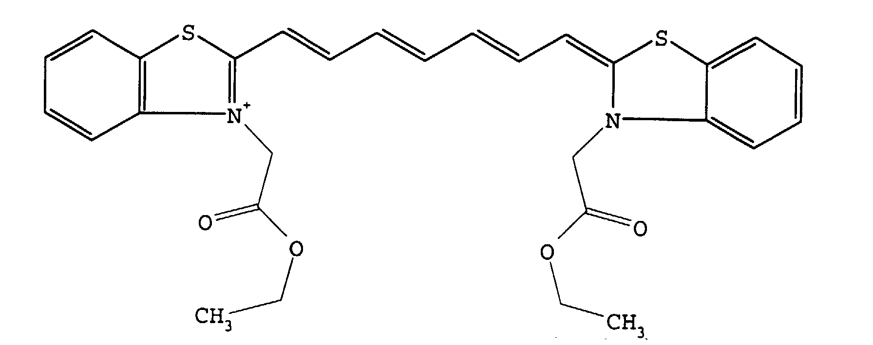
- IR-dyes are IR-cyanines dyes.
- Particularly useful IR-cyanine dyes are cyanines dyes with two acid groups, more preferably with two sulphonic groups. Still more preferably are cyanines dyes with two indolenine and two sulphonic acid groups. Most preferably is compound I with the structure as indicated
- Said dye is preferably present in said top layer preferably in an amount between 0.01 and 1 g/m 2 , more preferably in an amount between 0.05 and 0.20 g/m 2 .
- the top layer or the layer just underlying said top layer preferably includes a compound capable of converting light into heat.
- Suitable compounds capable of converting light into heat are preferably infrared absorbing components although the wavelength of absorption is not of particular importance as long as the absorption of the compound used is in the wavelength range of the light source used for image-wise exposure.
- Particularly useful compounds are for example dyes and in particular infrared dyes which can be the same as mentioned above, carbon black, metal carbides, borides, nitrides, carbonitrides, bronze-structured oxides and oxides structurally related to the bronze family but lacking the A component e.g. WO 2.9 .
- conductive polymer dispersion such as polypyrrole or polyaniline-based conductive polymer dispersions.
- Said compound capable of converting light into heat is preferaply present in the top layer but can also be included in an underlying layer.
- Said compound capable of converting light into heat is present in the imaging element preferably in an amount between 0.01 and 1 g/m 2 , more preferably in an amount between 0.05 and 0.50 g/m 2 .
- the top layer comprises hydrophobic particles dispersed in a cross-linked hydrophilic layer.
- a particularly suitable cross-linked hydrophilic layer may be obtained from a hydrophilic binder cross-linked with a cross-linking agent such as formaldehyde, glyoxal, polyisocyanate or a hydrolysed tetraalkyl orthosilicate. The latter is particularly preferred; most preferred is tetraethyl or tetramethyl orthosilicate.
- hydrophilic binder there may be used hydrophilic (co)polymers such as for example, homopolymers and copolymers of acrylamide, methylol acrylamide, methylol methacrylamide, acrylic acid, methacrylic acid, hydroxyethyl acrylate, hydroxyethyl methacrylate or maleic anhydride/vinylmethylether copolymers.
- the hydrophilicity of the (co)polymer or (co)polymer mixture used is preferably the same as or higher than the hydrophilicity of polyvinyl acetate hydrolyzed to at least an extent of 60 percent by weight, preferably 80 percent by weight.
- a preferred hydrophilic binder is polyvinylalcohol.
- the amount of crosslinking agent, in particular of tetraalkyl orthosilicate, is preferably at least 0.2 parts by weight per part by weight of hydrophilic binder, more preferably between 0.5 and 5 parts by weight, most preferably between 1.0 parts by weight and 3 parts by weight.
- a cross-linked hydrophilic layer used in accordance with the present invention preferably also contains substances that increase the mechanical strength and the porosity of the layer.
- colloidal silica may be used.
- the colloidal silica employed may be in the form of any commercially available water-dispersion of colloidal silica for example having an average particle size up to 40 nm, e.g. 20 nm.
- inert particles of larger size than the colloidal silica can be added e.g. silica prepared according to Stöber as described in J. Colloid and Interface Sci., Vol. 26, 1968, pages 62 to 69 or alumina particles or particles having an average diameter of at least 100 nm which are particles of titanium dioxide or other heavy metal oxides.
- the surface of the cross-linked hydrophilic layer is given a uniform rough texture consisting of microscopic hills and valleys, which serve as storage sites for water in background areas.
- the thickness of a cross-linked hydrophilic layer in a lithographic base in accordance with this embodiment may vary in the range of 0.2 to 25 ⁇ m and is preferably 1 to 10 ⁇ m.
- the hydrophobic polymer particles preferred in the embodiment of this invention are thermoplastic polymer particles.
- the hydrophobic thermoplastic polymer particles used in connection with the present invention preferably have a coagulation temperature above 50°C and more preferably above 70°C. Coagulation may result from softening or melting of the thermoplastic polymer particles under the influence of heat.
- There is no specific upper limit to the coagulation temperature of the thermoplastic hydrophobic polymer particles however the temperature should be sufficiently below the decomposition temperature of the polymer particles.
- the coagulation temperature is at least 10°C below the temperature at which the decomposition of the polymer particles occurs.
- hydrophobic polymer particles for use in connection with the present invention having preferably a Tg above 80°C are preferably polyvinyl chloride, polyvinylidene chloride, polyacrylonitrile, polyvinyl carbazole, copolymers or mixtures thereof. Most preferably used are polystyrene, polymethylmethacrylate or copolymers thereof.
- the weight average molecular weight of the polymers may range from 5,000 to 1,000,000g/mol as determined by GPC relative to polystyrene standards.
- the hydrophobic particles may have a particle size from 0.01 ⁇ m to 50 ⁇ m, more preferably between 0.05 mm and 10 mm and most preferably between 0.05 ⁇ m and 2 ⁇ m.
- the polymer particles are present as a dispersion in the aqueous coating liquid of the image-forming layer and may be prepared by the methods disclosed in US-P- 3 476 937 .
- Another method especially suitable for preparing an aqueous dispersion of the thermoplastic polymer particles comprises:
- the amount of hydrophobic thermoplastic polymer particles contained in the image-forming layer is preferably at least 20% by weight and more preferably at least 30% by weight and most preferably at least 40% by weight.
- the top layer comprises switchable polymers.
- Switchable polymers are polymers which by heating undergo a transition from hydrophobic to hydrophilic or vice versa.
- An example of a switchable polymer is poly-tetrahydropyranolmethacrylate.
- the support of the imaging element can be flexible or rigid.
- flexible support in connection with the present invention all kinds of flexible support can be used e. g. paper, polyethylene coated paper, but it is particularly preferred to use a plastic film e.g. substrated polyethylene terephthalate film, cellulose acetate film, polystyrene film, polycarbonate film, polyethylene film, polypropylene film.
- the plastic film support may be opaque or transparent.
- the amount of silica in the adhesion improving layer is between 200 mg per m2 and 750 mg per m2.
- the ratio of silica to hydrophilic binder is preferably more than 1 and the surface area of the colloidal silica is preferably at least 300 m2 per gram, more preferably at least 500 m2 per gram.
- the support can also be rigid, preferably an aluminum foil.
- a particularly preferred aluminum foil is an electrochemically grained and anodised aluminum support.
- the anodised aluminum support may be treated to improve the adhesive properties of its surface.
- the aluminum support may be silicated by treating its surface with sodium silicate solution at elevated temperature, e.g. 95°C.
- a phosphate treatment may be applied which involves treating the aluminum oxide surface with a phosphate solution that may further contain an inorganic fluoride.
- the aluminum oxide surface may be rinsed with a citric acid or citrate solution. This treatment may be carried out at room temperature or can be carried out at a slightly elevated temperature of about 30 to 50°C.
- a further interesting treatment involves rinsing the aluminum oxide surface with a bicarbonate solution.
- the aluminum oxide surface may be treated with polyvinylphosphonic acid, polyvinylmethylphosphonic acid, phosphoric acid esters of polyvinyl alcohol, polyvinylsulphonic acid, polyvinylbenzenesulphonic acid, sulphuric acid esters of polyvinyl alcohol, and acetals of polyvinyl alcohols formed by reaction with a sulphonated aliphatic aldehyde It is further evident that one or more of these post treatments may be carried out alone or in combination.
- the imaging element can contain other layers such as subbing layers and antihalo layers.
- the imaging element optionally contains between the support and the top layer a reflective layer.
- Said reflective layer can be any layer which reflects the IR-irradiation but is preferably aluminum with a high visual density e.g. vacuum deposited aluminum
- Imaging in connection with the present invention can be done with a thermal head.
- an image-wise scanning exposure is used involving the use of a laser that operates in the infrared or near-infrared, i.e. wavelength range of 700-1500 nm.
- laser diodes emitting in the near-infrared.
- Exposure of the imaging element can be performed with lasers with a short as well as with lasers with a long pixel dwell time. Preferred are lasers with a pixel dwell time between 0.005 ⁇ s and 20 ⁇ s.
- the imaging element After the exposure the imaging element is ready to be used as a lithographic printing plate.
- a dispersion was prepared by mixing 16.8 g of a dispersion containing 21.5% TiO 2 (average particle size 0.3 to 0.5 ⁇ m) and 2.5% polyvinylalcohol in deionized-water. Thereto 7.0 respectively 14g of a 20% polystyrene dispersion was added. To these dispersions was added 0.7 respectively 1.4 ml of a hydrolyzed 28.43% tetramethylorthosilicate solution. 0.1 of the IR-dye compound I was added to these dispersions. The dispersions are made up with water to a volume of 40 ml.
- the imaging elements were kept for 5 days at a temperature of 49°C and relative humidity of 20% in order to harden the polyvinylalcohol.
- the imaging elements were imaged with
- a dispersion was prepared by mixing 16.8 g of a dispersion containing 21.5% TiO 2 (average particle size 0.3 to 0.5 ⁇ m) and 2.5% polyvinylalcohol in deionized water. Thereto 11.24 g of a 12.45% polystyrene dispersion was added. To this dispersion was added 0.7 g of a hydrolyzed 28.43% tetramethylorthosilicate solution. 0.1 of a IR-dye compound with the structure as given below was added. The dispersion is made up with water to a volume of 30 ml.
- This dispersion was well stirred and coated on a subbed PET-support at a thickness of 30 ⁇ m and dried with hot air at 60°C for 2 hours. After coating the imaging element was kept for 5 days at a temperature of 49°C and relative humidity of 20% in order to harden the polyvinylalcohol.
- the imaging element was imaged with
Landscapes
- Engineering & Computer Science (AREA)
- Manufacturing & Machinery (AREA)
- Physics & Mathematics (AREA)
- Optics & Photonics (AREA)
- Photosensitive Polymer And Photoresist Processing (AREA)
- Printing Plates And Materials Therefor (AREA)
Abstract
Description
More specifically the invention is related to a heat sensitive non-ablatable wasteless imaging imaging element for preparing a lithographic printing plate with a difference in dye density between the image and non image areas.

- dissolving the hydrophobic thermoplastic polymer in an organic water immiscible solvent,
- dispersing the thus obtained solution in water or in an aqueous medium and
- removing the organic solvent by evaporation.
| Number | TiO2 + PVA | TMOS | PSTC | PST | Cpd I |
| 1 | 4.00 | 0.18 | 1.40 | 0.00 | 0.10 |
| 2 | 4.00 | 0.18 | 2.80 | 0.00 | 0.10 |
| 3 | 4.00 | 0.18 | 0.00 | 1.40 | 0.10 |
| 4 | 4.00 | 0.18 | 0.00 | 2.80 | 0.10 |
| 5 | 4.00 | 0.36 | 1.40 | 0.00 | 0.10 |
| 6 | 4.00 | 0.36 | 0.00 | 1.40 | 0.10 |
- Thermal head: dark blue image against a light blue background
- Laser recording : white image against a light blue background.
- Thermal head: light blue image against a dark blue background
- Laser recording : white image against a dark blue background.
Claims (9)
- A heat-sensitive non-ablatable wasteless imaging element for providing a lithographic printing plate, comprising on a support a top layer which is capable of forming by image-wise exposure image-wise hydrophobic and hydrophilic areas, characterized in that said imaging element contains an IR-dye capable of changing its optical density by exposure of the imaging element.
- An imaging element for making lithographic printing plates according to claim 1 wherein said IR-dye is an IR-cyanine dye.
- An imaging element for making lithographic printing plates according to claim 2 wherein said IR-cyanine dye comprises two acid groups.
- An imaging element for making lithographic printing plates according to claim 3 wherein said infrared cyanine dye comprises two indolenine groups.
- An imaging element for making lithographic printing plates according to claim 4 wherein said infrared cyanine dye is compound I with the structure as indicated

- An imaging element for making lithographic printing plates according to any of claims 1 to 5 wherein the top layer comprises hydrophobic particles dispersed in a cross-linked hydrophilic layer, said cross-linked hydrophilic layer obtained from a hydrophilic binder cross-linked with a cross-linking agent
- An imaging element for making lithographic printing plates according to claim 6 wherein said hydrophilic binder is polyvinylalcohol.
- An imaging element for making lithographic printing plates according to claim 6 or 7 wherein said cross-linking agent is a hydrolysed tetraalkylorthosilicate.
- An imaging element for making lithographic printing plates according to any of claims 1 to 5 wherein the top layer comprises a switchable polymer.
Priority Applications (1)
| Application Number | Priority Date | Filing Date | Title |
|---|---|---|---|
| EP19980203792 EP0925916B1 (en) | 1997-12-09 | 1998-11-10 | A heat sensitive non-ablatable wasteless imaging element for providing a lithographic printing plate with a difference in dye density between the image and non image areas |
Applications Claiming Priority (3)
| Application Number | Priority Date | Filing Date | Title |
|---|---|---|---|
| EP97203855 | 1997-12-09 | ||
| EP97203855 | 1997-12-09 | ||
| EP19980203792 EP0925916B1 (en) | 1997-12-09 | 1998-11-10 | A heat sensitive non-ablatable wasteless imaging element for providing a lithographic printing plate with a difference in dye density between the image and non image areas |
Publications (2)
| Publication Number | Publication Date |
|---|---|
| EP0925916A1 true EP0925916A1 (en) | 1999-06-30 |
| EP0925916B1 EP0925916B1 (en) | 2002-04-10 |
Family
ID=26147133
Family Applications (1)
| Application Number | Title | Priority Date | Filing Date |
|---|---|---|---|
| EP19980203792 Expired - Lifetime EP0925916B1 (en) | 1997-12-09 | 1998-11-10 | A heat sensitive non-ablatable wasteless imaging element for providing a lithographic printing plate with a difference in dye density between the image and non image areas |
Country Status (1)
| Country | Link |
|---|---|
| EP (1) | EP0925916B1 (en) |
Cited By (17)
| Publication number | Priority date | Publication date | Assignee | Title |
|---|---|---|---|---|
| US6653042B1 (en) | 1999-06-04 | 2003-11-25 | Fuji Photo Film Co., Ltd. | Lithographic printing plate precursor, method for producing the same, and method of lithographic printing |
| US6686125B2 (en) | 2000-01-14 | 2004-02-03 | Fuji Photo Film Co., Ltd. | Lithographic printing plate precursor |
| EP1428676A3 (en) * | 2002-12-12 | 2004-10-13 | Konica Minolta Holdings, Inc. | Printing plate material |
| WO2004089630A1 (en) * | 2003-04-14 | 2004-10-21 | Creo Inc. | Novel layers in printing plates, printing plates and method of use of printing plates |
| US6815137B2 (en) | 2000-12-28 | 2004-11-09 | Fuji Photo Film Co., Ltd. | Process for producing polymer fine particles and lithographic printing plate precursor using the same |
| EP1518711A3 (en) * | 2003-09-24 | 2005-10-12 | Konica Minolta Medical & Graphic Inc. | Planographic printing plate material and printing process |
| EP1614541A2 (en) | 2004-07-08 | 2006-01-11 | Agfa-Gevaert | Method of making a lithographic printing plate. |
| WO2006136543A2 (en) | 2005-06-21 | 2006-12-28 | Agfa Graphics Nv | Infrared absorbing dye |
| EP3431290A1 (en) | 2017-07-20 | 2019-01-23 | Agfa Nv | A lithographic printing plate precursor |
| WO2019219565A1 (en) | 2018-05-14 | 2019-11-21 | Agfa Nv | A lithographic printing plate precursor |
| WO2019243036A1 (en) | 2018-06-21 | 2019-12-26 | Agfa Nv | A lithographic printing plate precursor |
| WO2019243037A1 (en) | 2018-06-21 | 2019-12-26 | Agfa Nv | A lithographic printing plate precursor |
| EP3686011A1 (en) | 2019-01-23 | 2020-07-29 | Agfa Nv | A lithographic printing plate precursor |
| EP3875271A1 (en) | 2020-03-04 | 2021-09-08 | Agfa Nv | A lithographic printing plate precursor |
| EP3892469A1 (en) | 2020-04-10 | 2021-10-13 | Agfa Nv | Lithographic printing plate precursor |
| WO2021259648A1 (en) | 2020-06-24 | 2021-12-30 | Agfa Offset Bv | A lithographic printing plate precursor |
| EP4223534A1 (en) | 2022-02-07 | 2023-08-09 | Agfa Offset Bv | A lithographic printing plate precursor |
Citations (7)
| Publication number | Priority date | Publication date | Assignee | Title |
|---|---|---|---|---|
| US4034183A (en) * | 1974-10-10 | 1977-07-05 | Hoechst Aktiengesellschaft | Process for the production of planographic printing forms by means of laser beams |
| DD213530A1 (en) * | 1983-02-01 | 1984-09-12 | Leipzig Tech Hochschule | METHOD OF FORMING MANUFACTURE WITH THE HELP OF A LASER |
| DD217645A1 (en) * | 1983-09-19 | 1985-01-16 | Leipzig Tech Hochschule | METHOD FOR THE PRODUCTION OF FLAT PRINTING FORMS WITH LASER RADIATION |
| DD217914A1 (en) * | 1983-10-03 | 1985-01-23 | Leipzig Tech Hochschule | METHOD FOR THE PRODUCTION OF FLAT PRINTING FORMS WITH LASER RADIATION |
| EP0652483A1 (en) * | 1993-11-04 | 1995-05-10 | Minnesota Mining And Manufacturing Company | Lithographic printing plates |
| EP0694586A1 (en) * | 1994-07-29 | 1996-01-31 | Riedel-De Haen Aktiengesellschaft | Use of indoleninecyaninedisulfonic acid derivatives as infrared absorbing compounds |
| EP0773112A1 (en) * | 1995-11-09 | 1997-05-14 | Agfa-Gevaert N.V. | Heat sensitive imaging element and method for making a printing plate therewith |
-
1998
- 1998-11-10 EP EP19980203792 patent/EP0925916B1/en not_active Expired - Lifetime
Patent Citations (7)
| Publication number | Priority date | Publication date | Assignee | Title |
|---|---|---|---|---|
| US4034183A (en) * | 1974-10-10 | 1977-07-05 | Hoechst Aktiengesellschaft | Process for the production of planographic printing forms by means of laser beams |
| DD213530A1 (en) * | 1983-02-01 | 1984-09-12 | Leipzig Tech Hochschule | METHOD OF FORMING MANUFACTURE WITH THE HELP OF A LASER |
| DD217645A1 (en) * | 1983-09-19 | 1985-01-16 | Leipzig Tech Hochschule | METHOD FOR THE PRODUCTION OF FLAT PRINTING FORMS WITH LASER RADIATION |
| DD217914A1 (en) * | 1983-10-03 | 1985-01-23 | Leipzig Tech Hochschule | METHOD FOR THE PRODUCTION OF FLAT PRINTING FORMS WITH LASER RADIATION |
| EP0652483A1 (en) * | 1993-11-04 | 1995-05-10 | Minnesota Mining And Manufacturing Company | Lithographic printing plates |
| EP0694586A1 (en) * | 1994-07-29 | 1996-01-31 | Riedel-De Haen Aktiengesellschaft | Use of indoleninecyaninedisulfonic acid derivatives as infrared absorbing compounds |
| EP0773112A1 (en) * | 1995-11-09 | 1997-05-14 | Agfa-Gevaert N.V. | Heat sensitive imaging element and method for making a printing plate therewith |
Non-Patent Citations (1)
| Title |
|---|
| "A LITHOGRAPHIC PRINTING PLATE", RESEARCH DISCLOSURE, no. 333, 1 January 1992 (1992-01-01), pages 2, XP000281114 * |
Cited By (35)
| Publication number | Priority date | Publication date | Assignee | Title |
|---|---|---|---|---|
| US6653042B1 (en) | 1999-06-04 | 2003-11-25 | Fuji Photo Film Co., Ltd. | Lithographic printing plate precursor, method for producing the same, and method of lithographic printing |
| US6686125B2 (en) | 2000-01-14 | 2004-02-03 | Fuji Photo Film Co., Ltd. | Lithographic printing plate precursor |
| US6815137B2 (en) | 2000-12-28 | 2004-11-09 | Fuji Photo Film Co., Ltd. | Process for producing polymer fine particles and lithographic printing plate precursor using the same |
| EP1428676A3 (en) * | 2002-12-12 | 2004-10-13 | Konica Minolta Holdings, Inc. | Printing plate material |
| US7074545B2 (en) | 2002-12-12 | 2006-07-11 | Konica Minolta Holdings, Inc. | Printing plate material |
| CN1805850B (en) * | 2003-04-14 | 2010-12-15 | 柯达图像通信加拿大公司 | Novel layer in printing plate, printing plate and method of using printing plate |
| WO2004089630A1 (en) * | 2003-04-14 | 2004-10-21 | Creo Inc. | Novel layers in printing plates, printing plates and method of use of printing plates |
| US7323288B2 (en) | 2003-04-14 | 2008-01-29 | Kodak Graphic Communications Canada Company | Layers in printing plates, printing plates and method of use of printing plates |
| US7579133B2 (en) | 2003-04-14 | 2009-08-25 | Kodak Graphic Communications Canada Company | Processless lithographic printing plate precursor |
| EP1518711A3 (en) * | 2003-09-24 | 2005-10-12 | Konica Minolta Medical & Graphic Inc. | Planographic printing plate material and printing process |
| EP1614541A2 (en) | 2004-07-08 | 2006-01-11 | Agfa-Gevaert | Method of making a lithographic printing plate. |
| WO2006136543A2 (en) | 2005-06-21 | 2006-12-28 | Agfa Graphics Nv | Infrared absorbing dye |
| US8148042B2 (en) | 2005-06-21 | 2012-04-03 | Agfa Graphics Nv | Heat-sensitive imaging element |
| US8178282B2 (en) | 2005-06-21 | 2012-05-15 | Agfa Graphics Nv | Heat-sensitive imaging element |
| EP3431290A1 (en) | 2017-07-20 | 2019-01-23 | Agfa Nv | A lithographic printing plate precursor |
| WO2019015979A1 (en) | 2017-07-20 | 2019-01-24 | Agfa Nv | A lithographic printing plate precursor |
| WO2019219565A1 (en) | 2018-05-14 | 2019-11-21 | Agfa Nv | A lithographic printing plate precursor |
| US11813838B2 (en) | 2018-05-14 | 2023-11-14 | Agfa Offset Bv | Lithographic printing plate precursor |
| WO2019219560A1 (en) | 2018-05-14 | 2019-11-21 | Agfa Nv | A lithographic printing plate precursor |
| WO2019219570A1 (en) | 2018-05-14 | 2019-11-21 | Agfa Nv | A lithographic printing plate precursor |
| WO2019219577A1 (en) | 2018-05-14 | 2019-11-21 | Agfa Nv | A lithographic printing plate precursor |
| WO2019219574A1 (en) | 2018-05-14 | 2019-11-21 | Agfa Nv | A lithographic printing plate precursor |
| WO2019243036A1 (en) | 2018-06-21 | 2019-12-26 | Agfa Nv | A lithographic printing plate precursor |
| WO2019243037A1 (en) | 2018-06-21 | 2019-12-26 | Agfa Nv | A lithographic printing plate precursor |
| EP3587113A1 (en) | 2018-06-21 | 2020-01-01 | Agfa Nv | A lithographic printing plate precursor |
| EP3587112A1 (en) | 2018-06-21 | 2020-01-01 | Agfa Nv | A lithographic printing plate precursor |
| EP3686011A1 (en) | 2019-01-23 | 2020-07-29 | Agfa Nv | A lithographic printing plate precursor |
| WO2020152072A1 (en) | 2019-01-23 | 2020-07-30 | Agfa Nv | A lithographic printing plate precursor |
| EP3875271A1 (en) | 2020-03-04 | 2021-09-08 | Agfa Nv | A lithographic printing plate precursor |
| WO2021175571A1 (en) | 2020-03-04 | 2021-09-10 | Agfa Nv | A lithographic printing plate precursor |
| EP3892469A1 (en) | 2020-04-10 | 2021-10-13 | Agfa Nv | Lithographic printing plate precursor |
| WO2021204502A1 (en) | 2020-04-10 | 2021-10-14 | Agfa Nv | A lithographic printing plate precursor |
| WO2021259648A1 (en) | 2020-06-24 | 2021-12-30 | Agfa Offset Bv | A lithographic printing plate precursor |
| EP4223534A1 (en) | 2022-02-07 | 2023-08-09 | Agfa Offset Bv | A lithographic printing plate precursor |
| WO2023148114A1 (en) | 2022-02-07 | 2023-08-10 | Eco3 | A lithographic printing plate precursor |
Also Published As
| Publication number | Publication date |
|---|---|
| EP0925916B1 (en) | 2002-04-10 |
Similar Documents
| Publication | Publication Date | Title |
|---|---|---|
| EP0931647B1 (en) | A heat sensitive element and a method for producing lithographic plates therewith | |
| EP0864420B2 (en) | Heat-sensitive imaging element for making positive working printing plates | |
| US5948591A (en) | Heat sensitive imaging element and a method for producing lithographic plates therewith | |
| US6022667A (en) | Heat sensitive imaging element and a method for producing lithographic plates therewith | |
| EP0925916B1 (en) | A heat sensitive non-ablatable wasteless imaging element for providing a lithographic printing plate with a difference in dye density between the image and non image areas | |
| EP0908779B1 (en) | A method for making positive working printing plates from a heat mode sensitive imaging element | |
| EP0816070B1 (en) | A heat sensitive imaging element and a method for producing lithographic plates therewith | |
| EP0864419B1 (en) | Method for making positive working lithographic printing plates | |
| EP0839647B2 (en) | Method for making a lithographic printing plate with improved ink-uptake | |
| EP0881096B1 (en) | A heat sensitive imaging element and a method for producing lithographic plates therewith | |
| US6197478B1 (en) | Method for making a driographic printing plate involving the use of a heat-sensitive imaging element | |
| US6106996A (en) | Heat sensitive imaging element and a method for producing lithographic plates therewith | |
| EP0943451B3 (en) | A heat mode imaging element and a method for making positive working printing plates from said heat mode imaging element | |
| US6210857B1 (en) | Heat sensitive imaging element for providing a lithographic printing plate | |
| EP0832739B1 (en) | Method for making a lithographic printing plate involving the use of a heat-sensitive imaging element | |
| JP4257878B2 (en) | Heat-sensitive non-ablative and waste-free imaging element to provide a lithographic printing plate having a difference in dye concentration between image and non-image areas | |
| EP0960730B1 (en) | A heat sensitive imaging element for providing a lithographic printing plate | |
| US6071369A (en) | Method for making an lithographic printing plate with improved ink-uptake | |
| EP0881094B1 (en) | A heat sensitive imaging element and a method for producing lithographic plates therewith | |
| US6511782B1 (en) | Heat sensitive element and a method for producing lithographic plates therewith | |
| EP0914941B1 (en) | A method for making positive working printing plates from heat mode sensitive imaging element | |
| EP0950516B1 (en) | A heat mode sensitive imaging element for making positive working printing plates | |
| US6528237B1 (en) | Heat sensitive non-ablatable wasteless imaging element for providing a lithographic printing plate with a difference in dye density between the image and non image areas | |
| EP0881095B1 (en) | A heat sensitive imaging element and a method for producing lithographic plates therewith | |
| EP0967077B1 (en) | A heat sensitive imaging element and a method for producing lithographic plates therewith |
Legal Events
| Date | Code | Title | Description |
|---|---|---|---|
| PUAI | Public reference made under article 153(3) epc to a published international application that has entered the european phase |
Free format text: ORIGINAL CODE: 0009012 |
|
| AK | Designated contracting states |
Kind code of ref document: A1 Designated state(s): BE DE FR GB |
|
| AX | Request for extension of the european patent |
Free format text: AL;LT;LV;MK;RO;SI |
|
| 17P | Request for examination filed |
Effective date: 19991230 |
|
| AKX | Designation fees paid |
Free format text: BE DE FR GB |
|
| 17Q | First examination report despatched |
Effective date: 20010206 |
|
| GRAG | Despatch of communication of intention to grant |
Free format text: ORIGINAL CODE: EPIDOS AGRA |
|
| REG | Reference to a national code |
Ref country code: GB Ref legal event code: IF02 |
|
| GRAG | Despatch of communication of intention to grant |
Free format text: ORIGINAL CODE: EPIDOS AGRA |
|
| GRAH | Despatch of communication of intention to grant a patent |
Free format text: ORIGINAL CODE: EPIDOS IGRA |
|
| GRAH | Despatch of communication of intention to grant a patent |
Free format text: ORIGINAL CODE: EPIDOS IGRA |
|
| RAP1 | Party data changed (applicant data changed or rights of an application transferred) |
Owner name: AGFA-GEVAERT |
|
| GRAA | (expected) grant |
Free format text: ORIGINAL CODE: 0009210 |
|
| AK | Designated contracting states |
Kind code of ref document: B1 Designated state(s): BE DE FR GB |
|
| PG25 | Lapsed in a contracting state [announced via postgrant information from national office to epo] |
Ref country code: BE Free format text: LAPSE BECAUSE OF FAILURE TO SUBMIT A TRANSLATION OF THE DESCRIPTION OR TO PAY THE FEE WITHIN THE PRESCRIBED TIME-LIMIT Effective date: 20020410 |
|
| REF | Corresponds to: |
Ref document number: 69804750 Country of ref document: DE Date of ref document: 20020516 |
|
| ET | Fr: translation filed | ||
| PLBE | No opposition filed within time limit |
Free format text: ORIGINAL CODE: 0009261 |
|
| STAA | Information on the status of an ep patent application or granted ep patent |
Free format text: STATUS: NO OPPOSITION FILED WITHIN TIME LIMIT |
|
| 26N | No opposition filed |
Effective date: 20030113 |
|
| REG | Reference to a national code |
Ref country code: GB Ref legal event code: 732E |
|
| REG | Reference to a national code |
Ref country code: FR Ref legal event code: TP |
|
| REG | Reference to a national code |
Ref country code: FR Ref legal event code: PLFP Year of fee payment: 19 |
|
| REG | Reference to a national code |
Ref country code: FR Ref legal event code: PLFP Year of fee payment: 20 |
|
| REG | Reference to a national code |
Ref country code: DE Ref legal event code: R081 Ref document number: 69804750 Country of ref document: DE Owner name: AGFA NV, BE Free format text: FORMER OWNER: AGFA GRAPHICS N.V., MORTSEL, BE |
|
| PGFP | Annual fee paid to national office [announced via postgrant information from national office to epo] |
Ref country code: FR Payment date: 20171020 Year of fee payment: 20 Ref country code: DE Payment date: 20171010 Year of fee payment: 20 |
|
| PGFP | Annual fee paid to national office [announced via postgrant information from national office to epo] |
Ref country code: GB Payment date: 20171020 Year of fee payment: 20 |
|
| REG | Reference to a national code |
Ref country code: FR Ref legal event code: CD Owner name: AGFA NV, BE Effective date: 20180628 |
|
| REG | Reference to a national code |
Ref country code: DE Ref legal event code: R071 Ref document number: 69804750 Country of ref document: DE |
|
| REG | Reference to a national code |
Ref country code: GB Ref legal event code: PE20 Expiry date: 20181109 |
|
| PG25 | Lapsed in a contracting state [announced via postgrant information from national office to epo] |
Ref country code: GB Free format text: LAPSE BECAUSE OF EXPIRATION OF PROTECTION Effective date: 20181109 |