EP0925809B1 - Physical exercise device simulating the use of a bicycle - Google Patents
Physical exercise device simulating the use of a bicycle Download PDFInfo
- Publication number
- EP0925809B1 EP0925809B1 EP19970830694 EP97830694A EP0925809B1 EP 0925809 B1 EP0925809 B1 EP 0925809B1 EP 19970830694 EP19970830694 EP 19970830694 EP 97830694 A EP97830694 A EP 97830694A EP 0925809 B1 EP0925809 B1 EP 0925809B1
- Authority
- EP
- European Patent Office
- Prior art keywords
- frame
- curved
- cross
- supporting means
- members
- Prior art date
- Legal status (The legal status is an assumption and is not a legal conclusion. Google has not performed a legal analysis and makes no representation as to the accuracy of the status listed.)
- Expired - Lifetime
Links
Images


Classifications
-
- A—HUMAN NECESSITIES
- A63—SPORTS; GAMES; AMUSEMENTS
- A63B—APPARATUS FOR PHYSICAL TRAINING, GYMNASTICS, SWIMMING, CLIMBING, OR FENCING; BALL GAMES; TRAINING EQUIPMENT
- A63B26/00—Exercising apparatus not covered by groups A63B1/00 - A63B25/00
- A63B26/003—Exercising apparatus not covered by groups A63B1/00 - A63B25/00 for improving balance or equilibrium
-
- A—HUMAN NECESSITIES
- A63—SPORTS; GAMES; AMUSEMENTS
- A63B—APPARATUS FOR PHYSICAL TRAINING, GYMNASTICS, SWIMMING, CLIMBING, OR FENCING; BALL GAMES; TRAINING EQUIPMENT
- A63B22/00—Exercising apparatus specially adapted for conditioning the cardio-vascular system, for training agility or co-ordination of movements
- A63B22/06—Exercising apparatus specially adapted for conditioning the cardio-vascular system, for training agility or co-ordination of movements with support elements performing a rotating cycling movement, i.e. a closed path movement
- A63B22/0605—Exercising apparatus specially adapted for conditioning the cardio-vascular system, for training agility or co-ordination of movements with support elements performing a rotating cycling movement, i.e. a closed path movement performing a circular movement, e.g. ergometers
- A63B2022/0635—Exercising apparatus specially adapted for conditioning the cardio-vascular system, for training agility or co-ordination of movements with support elements performing a rotating cycling movement, i.e. a closed path movement performing a circular movement, e.g. ergometers specially adapted for a particular use
- A63B2022/0641—Exercising apparatus specially adapted for conditioning the cardio-vascular system, for training agility or co-ordination of movements with support elements performing a rotating cycling movement, i.e. a closed path movement performing a circular movement, e.g. ergometers specially adapted for a particular use enabling a lateral movement of the exercising apparatus, e.g. for simulating movement on a bicycle
Definitions
- the present invention relates to a physical exercise device simulating the use of a bicycle.
- this bicycle-like frame instead of including wheels, is provided with a supporting base statically supported on a floor, so as to allow a user to perform, even in a comparatively small size closed room, gymnastic exercises, like those performed in cycling.
- the exercises performed thereon do not involve all of the body muscles which are involved in the use of a conventional bicycle, for example the muscles allowing the bicycle to be held in a balanced or equilibrium condition, both in a vertical attitude and in a slanted attitude, for example on curved portions of roads and the like.
- Document DE 29 813 828 U discloses an example of a physical arranging device.
- the aim of the present invention is to solve the above mentioned problem, by providing a physical exercise device or implement adapted to fully simulate the use of a conventional bicycle, thereby allowing to properly exercise all of the muscles which are usually involved in the use of a conventional bicycle.
- a main object of the present invention is to provide such a physical exercise device which is also adapted to exercise those body muscles which, in the use of a conventional bicycle, cooperate to hold the bicycle in an equilibrium condition, both as the bicycle is driven on a rectilinear road and as it is driven on curved parts of the road.
- Another object of the present invention is to provide such a physical exercise device which is very safe and reliable in operation.
- Yet another object of the present invention is to provide such a physical exercise device which can be easily used in comparatively small size closed rooms.
- the physical exercise device or implement comprises a supporting frame 1, which includes a seat 2, a handlebar 3 as well as a pair of pedals 4, which elements are arranged likewise to the arrangement of the seat, handlebar and pair of pedals of a conventional bicycle.
- the frame 1 is substantially made as the prior implements simulating a bicycle.
- the frame 1 of the device according to the invention is provided with supporting means, allowing the frame 1 to swing, in operation, in its longitudinal middle plane and/or transversely of said longitudinal middle plane.
- said supporting means can comprise a pair of curved elements 5a and 5b which have their bottom end portions coupled to the base 6 of the frame 1 and being arranged transversely of the longitudinal middle plane of said frame 1.
- the two curved elements 5a and 5b are arranged parallel to one another and are spaced from one another along the longitudinal extension of the frame 1.
- the two curved elements 5a and 5b bear by their curved side on the floor, so as to allow, in operation, the supporting frame 1 to swing transversely of its longitudinal middle plane.
- Figure 2 illustrates another embodiment in which the supporting means of said frame 1, which, likewise to the embodiments shown in Figures 1 and 3 will allow the frame 1 to swing transversely of its longitudinal middle plane, comprise a curved supporting element 8, bearing by its curved side against the floor and being connected at the bottom to the base 6.
- the swinging of the frame 1 is obtained, instead of using a pair of curved elements 5a, 5b or 7a, 7b, by a continuous curved surface, the curvature axis thereof substantially lies in the longitudinal middle plane of the frame 1.
- the base 6 is preferably formed by a pair of cross members 9a, 9b, parallel to one another and spaced from one another along the longitudinal extension of the frame 1, and being coupled at the central portion thereof by a longitudinal middle beam 10.
- the supporting means comprise a cup-like member 11 which is coupled, by its base, to the bottom of a plate 12, in turn connected under the base 6.
- the cut-like element 11 is preferably coupled to a central region of the base 6, so as to allow the implement frame to swing in any desired directions.
- the supporting means comprise a pair of cup-like elements 13a and 13b, which are coupled at the bottom thereof to the base 6 and being spaced from one another along the longitudinal extension of the implement.
- the base 6 is pivoted to the bearing foot elements 14a and 14b about a pivot axis 15, which is substantially horizontal and lies in the longitudinal middle plane of the frame 1, so as to allow said frame 1 to swing about said pivot axis 5.
- Figure 9 illustrates another embodiment in which the swinging movement of the frame 1, both longitudinally and transversely, as well as in a composite manner with respect to the mentioned two swinging directions, is obtained by four resilient bearing foot elements, comprising springs 16 spaced from one another and from the longitudinal middle plane, as well as from the transversal or cross middle plane of the frame 1.
- Figure 10 illustrates yet another embodiment, similar to that shown in Figure 2, where the supporting means comprise a curved supporting element 17 which, in this case, is provided with a curvature axis perpendicular to the longitudinal middle plane of the frame 1.
- Figures 11 to 14 illustrate yet another embodiment of the physical exercise device according to the present invention, in which the supporting means comprise a pair of curved supporting elements 18 and 19 which are diagonally coupled at the bottom of the base 6, so as to define two curved bearing surfaces for the base 6.
- the curved supporting elements 18 and 19 cross one another at a central vertical axis of the frame 1 and define two bearing curved surfaces, having curvature axes respectively parallel and perpendicular to the longitudinal middle plane of the frame 1, to allow said frame 1 to swing both in its longitudinal middle plane and transversely of said longitudinal middle plane.
- the physical exercise device further comprises limiting means for limiting the swinging amplitude of the frame 1.
- Said swinging amplitude limiting means can merely comprise, as shown in Figure 3, side extensions of the cross members 9a and 9b of the base 6, or they can also comprise suitable extensions 20, 21 coupled to the end portions of the cross members 9a and 9b of the base 6, as shown in Figures 4 and 8.
- the foot elements 22, in a vertical equilibrium condition of the frame 1, are spaced from the floor, and they can be of a height adjustable type, in order to allow the swinging amplitude of the frame 1 to be easily adjusted or changed.
- springs 23 are provided to counter-bias the swinging movement in a set direction, or in another set direction, of the frame 1 about the pivot axis 15.
Description
- The present invention relates to a physical exercise device simulating the use of a bicycle.
- Physical or gymnastic devices or implements, provided with pedals allowing a user to pedal with physical movements like those of a bicycle, are already known.
- These prior devices or implements conventionally comprise a supporting frame, which supports a seat, a handlebar as well as a pair of pedals, which elements are arranged with an arrangement similar to that of the seat, handlebar and pedals of a conventional bicycle.
- However, this bicycle-like frame, instead of including wheels, is provided with a supporting base statically supported on a floor, so as to allow a user to perform, even in a comparatively small size closed room, gymnastic exercises, like those performed in cycling.
- The above mentioned bicycle-like devices or implements are broadly diffused since they allow to perform, at any desired times, physical or gymnastic exercises, like those performed on a bicycle, without compelling the user to follow high traffic roads, and without the effects of meteorological agents.
- On the other hand, notwithstanding the above mentioned advantages, the mentioned prior physical exercise devices have the drawback that they do not allow to exercise all of the body muscles which, on the contrary, would be properly exercised on a conventional bicycle.
- In fact, since the construction of the prior devices is of a static type, the exercises performed thereon do not involve all of the body muscles which are involved in the use of a conventional bicycle, for example the muscles allowing the bicycle to be held in a balanced or equilibrium condition, both in a vertical attitude and in a slanted attitude, for example on curved portions of roads and the like.
- In this connection it should be apparent that in a slanted position, which can not be assumed in the mentioned prior devices, the body muscles would operate in a different manner from the operation in a vertical attitude.
- Document DE 29 813 828 U discloses an example of a physical exercice device.
- Accordingly, the aim of the present invention is to solve the above mentioned problem, by providing a physical exercise device or implement adapted to fully simulate the use of a conventional bicycle, thereby allowing to properly exercise all of the muscles which are usually involved in the use of a conventional bicycle.
- Within the scope of the above mentioned aim, a main object of the present invention is to provide such a physical exercise device which is also adapted to exercise those body muscles which, in the use of a conventional bicycle, cooperate to hold the bicycle in an equilibrium condition, both as the bicycle is driven on a rectilinear road and as it is driven on curved parts of the road.
- Another object of the present invention is to provide such a physical exercise device which is very safe and reliable in operation.
- Yet another object of the present invention is to provide such a physical exercise device which can be easily used in comparatively small size closed rooms.
- According to one aspect of the present invention, the above mentioned aim and objects, as well as yet other objects, which will become more apparent hereinafter, are achieved by a physical exercise device according to
claim 1 - Further characteristics and advantages of the physical exercise device according to the present invention will become more apparent hereinafter from the following detailed disclosure of some preferred, though not exclusive, embodiments of said device which is illustrated, by way of an indicative, but not limitative, example, in the figures of the accompanying drawings, where:
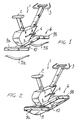
- Figure 1 is a perspective view illustrating a first embodiment of the physical exercise device according to the invention, in which the supporting means comprises a pair of curved elements, coupled at the bottom to the frame of the device;
- Figure 2 is a further perspective view illustrating a second embodiment of the subject physical exercise device, in which the supporting means comprise a curved supporting element, connected to the bottom of the device frame;
- Figure 3 is a further perspective view illustrating a third embodiment of the subject physical exercise device, similar to that shown in Figure 1, in which the pair of curved elements is directly formed on the base of the device frame;
- Figure 4 is a further perspective view illustrating a fourth embodiment of the subject physical exercise device, including means for limiting the swinging movement of the device;
- Figure 5 is a further perspective view illustrating yet another embodiment of the invention, including modified means for limiting the device swinging movement;
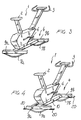
- Figure 6 is a further perspective view illustrating yet another embodiment of the subject physical exercise device, the supporting means thereof being shown in an exploded form;
- Figure 7 is yet another perspective view illustrating a further embodiment of the physical exercise device according to the invention;
- Figure 8 is an embodiment which is not part of the invention;
- Figure 9 is an embodiment which is not part of the invention;
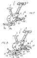
- Figure 10 is a further perspective view illustrating yet another embodiment of the physical exercise device according to the invention;
- Figure 11 is yet another perspective view illustrating a further embodiment of the physical exercise device according to the present invention, in which the supporting means allow the device to swing both longitudinally and transversely;
- Figure 12 is a side elevation view illustrating a detail related to the base of the subject physical exercise device shown in Figure 11;
- Figure 13 is a front elevation view illustrating a detail related to the base of the physical exercise device or implement shown in Figure 11; and
- Figure 14 is a bottom plan view illustrating the base of the physical exercise device or implement shown in Figure 11.
-
- With reference to the number references of the above mentioned drawing figures, the physical exercise device or implement, according to the present invention, comprises a supporting
frame 1, which includes aseat 2, ahandlebar 3 as well as a pair ofpedals 4, which elements are arranged likewise to the arrangement of the seat, handlebar and pair of pedals of a conventional bicycle. - Thus, the
frame 1 is substantially made as the prior implements simulating a bicycle. - However, differently from prior bicycle like devices, the
frame 1 of the device according to the invention is provided with supporting means, allowing theframe 1 to swing, in operation, in its longitudinal middle plane and/or transversely of said longitudinal middle plane. - As is clearly shown in Figure 1, said supporting means can comprise a pair of curved elements 5a and 5b which have their bottom end portions coupled to the
base 6 of theframe 1 and being arranged transversely of the longitudinal middle plane of saidframe 1. - The two curved elements 5a and 5b are arranged parallel to one another and are spaced from one another along the longitudinal extension of the
frame 1. - The two curved elements 5a and 5b bear by their curved side on the floor, so as to allow, in operation, the supporting
frame 1 to swing transversely of its longitudinal middle plane. - As is clearly shown in Figure 3, the curved elements, which in this figure have been indicated by the reference numbers 7a and 7b, can be directly formed in the
base 6 of the supportingframe 1. - Figure 2 illustrates another embodiment in which the supporting means of said
frame 1, which, likewise to the embodiments shown in Figures 1 and 3 will allow theframe 1 to swing transversely of its longitudinal middle plane, comprise a curved supporting element 8, bearing by its curved side against the floor and being connected at the bottom to thebase 6. - During the operation of the embodiment shown in Figure 2, the swinging of the
frame 1 is obtained, instead of using a pair of curved elements 5a, 5b or 7a, 7b, by a continuous curved surface, the curvature axis thereof substantially lies in the longitudinal middle plane of theframe 1. - The
base 6 is preferably formed by a pair ofcross members 9a, 9b, parallel to one another and spaced from one another along the longitudinal extension of theframe 1, and being coupled at the central portion thereof by alongitudinal middle beam 10. - In the embodiment shown in Figure 6, the supporting means comprise a cup-
like member 11 which is coupled, by its base, to the bottom of aplate 12, in turn connected under thebase 6. - The cut-
like element 11 is preferably coupled to a central region of thebase 6, so as to allow the implement frame to swing in any desired directions. - In Figure 7, the supporting means comprise a pair of cup-like elements 13a and 13b, which are coupled at the bottom thereof to the
base 6 and being spaced from one another along the longitudinal extension of the implement. - In Figure 8, the
base 6 is pivoted to the bearing foot elements 14a and 14b about apivot axis 15, which is substantially horizontal and lies in the longitudinal middle plane of theframe 1, so as to allowsaid frame 1 to swing about said pivot axis 5. - Figure 9 illustrates another embodiment in which the swinging movement of the
frame 1, both longitudinally and transversely, as well as in a composite manner with respect to the mentioned two swinging directions, is obtained by four resilient bearing foot elements, comprisingsprings 16 spaced from one another and from the longitudinal middle plane, as well as from the transversal or cross middle plane of theframe 1. - Figure 10 illustrates yet another embodiment, similar to that shown in Figure 2, where the supporting means comprise a curved supporting
element 17 which, in this case, is provided with a curvature axis perpendicular to the longitudinal middle plane of theframe 1. - Figures 11 to 14 illustrate yet another embodiment of the physical exercise device according to the present invention, in which the supporting means comprise a pair of curved supporting
elements base 6, so as to define two curved bearing surfaces for thebase 6. - The curved supporting
elements frame 1 and define two bearing curved surfaces, having curvature axes respectively parallel and perpendicular to the longitudinal middle plane of theframe 1, to allowsaid frame 1 to swing both in its longitudinal middle plane and transversely of said longitudinal middle plane. - The physical exercise device according to the present invention further comprises limiting means for limiting the swinging amplitude of the
frame 1. - Said swinging amplitude limiting means can merely comprise, as shown in Figure 3, side extensions of the
cross members 9a and 9b of thebase 6, or they can also comprisesuitable extensions cross members 9a and 9b of thebase 6, as shown in Figures 4 and 8. - In Figure 5, in addition to the
extensions 20, side bearingfoot elements 22 are moreover provided, said side bearing foot elements being coupled to theextensions 20 and projecting at the bottom thereof. - The
foot elements 22, in a vertical equilibrium condition of theframe 1, are spaced from the floor, and they can be of a height adjustable type, in order to allow the swinging amplitude of theframe 1 to be easily adjusted or changed. - In the embodiment shown in Figure 8
springs 23 are provided to counter-bias the swinging movement in a set direction, or in another set direction, of theframe 1 about thepivot axis 15. - From the above disclosure and from the figures of the accompanying drawings, it should be apparent that the invention fully achieves the intended aim and objects.
- In particular, the fact is to be pointed out that a physical exercise device or implement has been provided which, owing to the capability thereof of swinging longitudinally, transversely, or in a composite manner along the two mentioned swinging directions, would allow all of the body muscles to be exercised or affected, likewise in a conventional type of bicycle.
- While the invention has been disclosed and illustrated with reference to several embodiments thereof, it should be apparent that the disclosed embodiments are susceptible to many modifications and variations, all of which will come within the scope of the appended claims.
Claims (11)
- A physical exercise device to be supported on a floor, for simulating a use of a bicycle, comprising a device frame (1) supporting a seat (2), a handlebar (3) and a pair of pedals (4) simulating a bicycle, said frame (1) further comprising swinging supporting means (5a,5b,7a,7b,8, 11,13a,13b,14a,14b,16,17,18,19) swingably supporting said frame for allowing said frame to swing, said frame (1) having a base frame comprising a pair of cross-members (9a,9b), parallel to one another and coupled by a longitudinal middle beam (10), said handlebar (3) being rigidly fixed to said frame (1), characterized in that said swinging supporting means comprise at least a curved element coupled to said cross members (9a,9b) and having convex portions adapted to bear on said floor to allow said frame to perform swinging movements longitudinally and/or transversely of a longitudinal middle plane of said frame.
- A device according to Claim 1, characterized in that said supporting means comprises a pair of curved elements (5a,5b) each having end portions thereof coupled to a respective said cross-members (9a,9b) of said frame base, said curved elements (5a,5b;7a,7b) being arranged transversely of said longitudinal middle plane and being spaced from one another along a longitudinal extension of said frame (1).
- A device according to Claim 2, characterized in that said pair of curved elements (7a,7b) is directly formed with said cross-members (9a,9b) of said frame (1).
- A device according to Claim 1, characterized in that said supporting means comprise a single curved element (8) curved at a bottom thereof and coupled, at said bottom thereof, to said frame cross-members (9a,9b), and that said single curved element (8) has a curvature axis thereof arranged on said longitudinal plane.
- A device according to claims 1, characterized in that said supporting means comprise a single curved element (17) curved at a bottom thereof and compled, at said bottom single curved element (17) has a curvature axis thereof arranged substantially perpendicular to said longitudinal middle plane.
- A device according to Claim 1, characterized in that said supporting means comprises a cup-like member (11), having a base thereof coupled to a central bottom region of a plate (12) coupled to said frame cross-members (9a,9b).
- A device according to Claims 1 and 6, characterized in that said supporting means comprise two cup-like members (13a,13b), each having a base thereof coupled to the bottom of a respective cross-member of said frame cross-member (9a,9b).
- A device according to any preceding claims, characterized in that said supporting means comprise a pair of curved elements connected to the bottom of the base of the frame and crossing one another at a central vertical axis of said frame, said pair of curved elements defining two curved bearing surfaces having curvature axes respectively parallel and perpendicular to said longitudinal middle plane.
- A device according to Claim 1, characterized in that said device further comprises means (20,22) for limiting the swinging amplitude of said frame.
- A device according to claim 9, characterized in that said limiting means comprise side extensions (20) of said cross-members 9a,9b) of said frame.
- A device according to Claim 10, characterized in that said side extensions are provided with bearing foot elements (22) which, under a vertical equilibrium condition of said frame (1), are spaced above the floor and the height of which can be adjusted.
Priority Applications (2)
| Application Number | Priority Date | Filing Date | Title |
|---|---|---|---|
| DE1997626296 DE69726296T2 (en) | 1997-12-23 | 1997-12-23 | Exercise machine that simulates the use of a bicycle |
| EP19970830694 EP0925809B1 (en) | 1997-12-23 | 1997-12-23 | Physical exercise device simulating the use of a bicycle |
Applications Claiming Priority (1)
| Application Number | Priority Date | Filing Date | Title |
|---|---|---|---|
| EP19970830694 EP0925809B1 (en) | 1997-12-23 | 1997-12-23 | Physical exercise device simulating the use of a bicycle |
Publications (2)
| Publication Number | Publication Date |
|---|---|
| EP0925809A1 EP0925809A1 (en) | 1999-06-30 |
| EP0925809B1 true EP0925809B1 (en) | 2003-11-19 |
Family
ID=8230909
Family Applications (1)
| Application Number | Title | Priority Date | Filing Date |
|---|---|---|---|
| EP19970830694 Expired - Lifetime EP0925809B1 (en) | 1997-12-23 | 1997-12-23 | Physical exercise device simulating the use of a bicycle |
Country Status (2)
| Country | Link |
|---|---|
| EP (1) | EP0925809B1 (en) |
| DE (1) | DE69726296T2 (en) |
Cited By (1)
| Publication number | Priority date | Publication date | Assignee | Title |
|---|---|---|---|---|
| WO2022109643A1 (en) | 2020-11-24 | 2022-06-02 | Kogler Thomas | Curve simulation apparatus for a bicycle ergometer |
Families Citing this family (21)
| Publication number | Priority date | Publication date | Assignee | Title |
|---|---|---|---|---|
| KR19990033624U (en) * | 1999-05-08 | 1999-08-16 | 임정수 | Movable bike |
| ATE295205T1 (en) * | 2000-01-26 | 2005-05-15 | Daum Gmbh & Co Kg | TRAINING DEVICE |
| NO315933B1 (en) | 2000-12-22 | 2003-11-17 | Flexiped As | Exercise device with imbalance to train a person's musculature |
| US9357812B2 (en) | 2002-08-19 | 2016-06-07 | APOS—Medical and Sports Technologies Ltd. | Proprioceptive/kinesthetic apparatus and method |
| US8758207B2 (en) | 2002-08-19 | 2014-06-24 | APOS—Medical and Sports Technologies Ltd. | Proprioceptive/kinesthetic apparatus and method |
| DE102007007989A1 (en) * | 2007-02-17 | 2008-08-28 | Maik Schnitzer | Ellipse trainer for e.g. additional fitness training of abdominal musculature, has stroke movement producing system connected with support base and for inclining trainer, for shifting body stress to train abdominal musculature |
| KR100967215B1 (en) * | 2008-03-20 | 2010-07-05 | 김주리 | A lower-body exercising device of seat |
| IT1399546B1 (en) * | 2010-03-11 | 2013-04-19 | Edil Blitz Di Novelli Vittorio & C S N C | BICYCLE ROOM |
| US8157714B2 (en) * | 2010-04-13 | 2012-04-17 | Balanced Body, Inc. | Dynamic balance reformer exercise apparatus |
| ITFO20100001A1 (en) * | 2010-04-22 | 2011-10-23 | Forti Ettore & Figlio S N C | FIXED BICYCLE WITH TILTING AND OSCILLATING FRAME WHICH SIMULATOR CYCLE FOR RISING TRAINING |
| KR101750942B1 (en) | 2010-06-29 | 2017-06-26 | 아포스-메디컬 앤드 스포츠 테크놀로지즈 엘티디. | Device and methods for treating a lower limb joint pathology and lower limb pain |
| US10010743B2 (en) | 2010-07-02 | 2018-07-03 | APOS—Medical and Sports Technology Ltd. | Device and methods for tuning a skeletal muscle |
| WO2012146230A1 (en) * | 2011-04-24 | 2012-11-01 | Martin Kraiss | Arm and leg powered ergometric training device, ergometer, indoor cycle or exercise cycle |
| KR102020832B1 (en) | 2011-12-08 | 2019-09-11 | 아포스-메디컬 앤드 스포츠 테크놀로지즈 엘티디. | Device and methods for treating neurological disorders |
| ITRA20120022A1 (en) * | 2012-10-30 | 2014-05-01 | Edil Blitz Di Novelli Vittorio & C S N C | BICYCLE ROOM. |
| EP3634169A4 (en) | 2015-06-11 | 2020-07-29 | APOS Medical Assets Ltd. | Modular footwear protuberance assembly |
| ITUB20153906A1 (en) * | 2015-09-25 | 2017-03-25 | Lentini Gaspare Mattia | GYMNASTIC TOOL |
| IT201600092998A1 (en) * | 2016-09-15 | 2018-03-15 | Edil Blitz Di Novelli Vittorio & C S N C | PERFECTED BEDROOM BICYCLE. |
| DE102017209989A1 (en) * | 2017-06-13 | 2018-12-13 | Icaros Gmbh | training device |
| EP4279152A1 (en) * | 2022-05-19 | 2023-11-22 | Technogym S.p.A. | Exercise machine for simulating a cycling action |
| US20230405397A1 (en) * | 2022-06-21 | 2023-12-21 | Beth Ann Lucas | Exercise system for enabling lateral tilting of a stationary bicycle |
Family Cites Families (5)
| Publication number | Priority date | Publication date | Assignee | Title |
|---|---|---|---|---|
| FR2602150B1 (en) * | 1986-07-30 | 1990-07-27 | Maugard Michel | CYCLIST TRAINER |
| US4743012A (en) * | 1987-07-23 | 1988-05-10 | Kim Yong N | Bicycle exercising device |
| EP0354785B1 (en) * | 1988-08-10 | 1993-03-31 | Tokyo Sintered Metals Corp. | Cycle type athletic equipment |
| US5145477A (en) * | 1992-01-09 | 1992-09-08 | Sihui Han | Spring saddle cycle |
| DE29713828U1 (en) * | 1997-08-02 | 1997-10-09 | Daum Electronic Gmbh | Exercise machine like a stationary bike |
-
1997
- 1997-12-23 EP EP19970830694 patent/EP0925809B1/en not_active Expired - Lifetime
- 1997-12-23 DE DE1997626296 patent/DE69726296T2/en not_active Expired - Fee Related
Cited By (1)
| Publication number | Priority date | Publication date | Assignee | Title |
|---|---|---|---|---|
| WO2022109643A1 (en) | 2020-11-24 | 2022-06-02 | Kogler Thomas | Curve simulation apparatus for a bicycle ergometer |
Also Published As
| Publication number | Publication date |
|---|---|
| DE69726296T2 (en) | 2004-09-09 |
| EP0925809A1 (en) | 1999-06-30 |
| DE69726296D1 (en) | 2003-12-24 |
Similar Documents
| Publication | Publication Date | Title |
|---|---|---|
| EP0925809B1 (en) | Physical exercise device simulating the use of a bicycle | |
| US5299997A (en) | Horse-riding type exerciser | |
| CN101108274B (en) | Static pedaling fitness apparatus with lateral swinging | |
| KR200207040Y1 (en) | Movable bike | |
| US5453066A (en) | Horse riding type exerciser | |
| US5603675A (en) | Foldable striding exerciser | |
| US5356358A (en) | Horse-riding type exerciser | |
| US5330404A (en) | Exercise apparatus | |
| US7530927B2 (en) | Stepping exerciser | |
| US5441469A (en) | Exercise machine for realistic simulation of boat rowing | |
| US5423731A (en) | Exercise device with two seats | |
| US5496246A (en) | Resilient tension exercise apparatus | |
| US7156790B2 (en) | Training apparatus/chair | |
| US20080026916A1 (en) | Stepping exerciser | |
| US5342261A (en) | Adjustable cycling apparatus | |
| US20070049467A1 (en) | Exercise apparatus | |
| CA2206028A1 (en) | Fitness-balance board | |
| US4650181A (en) | Dynamic rowing machine | |
| US6921353B2 (en) | Stepping exerciser having rotatable foot pedals | |
| US20070054782A1 (en) | Exercise apparatus | |
| US2803461A (en) | Exercising apparatus | |
| EP0810007B1 (en) | Physical training implement for exercising abdominal muscles | |
| US5823915A (en) | Exercise bicycle | |
| US5938569A (en) | Stepping and swinging exerciser | |
| ES2198292T3 (en) | SADDLES FOR PEDAL MACHINES. |
Legal Events
| Date | Code | Title | Description |
|---|---|---|---|
| PUAI | Public reference made under article 153(3) epc to a published international application that has entered the european phase |
Free format text: ORIGINAL CODE: 0009012 |
|
| AK | Designated contracting states |
Kind code of ref document: A1 Designated state(s): DE FR |
|
| AX | Request for extension of the european patent |
Free format text: AL;LT;LV;MK;RO;SI |
|
| 17P | Request for examination filed |
Effective date: 19991228 |
|
| AKX | Designation fees paid |
Free format text: DE FR |
|
| 17Q | First examination report despatched |
Effective date: 20020125 |
|
| GRAH | Despatch of communication of intention to grant a patent |
Free format text: ORIGINAL CODE: EPIDOS IGRA |
|
| GRAS | Grant fee paid |
Free format text: ORIGINAL CODE: EPIDOSNIGR3 |
|
| GRAA | (expected) grant |
Free format text: ORIGINAL CODE: 0009210 |
|
| AK | Designated contracting states |
Kind code of ref document: B1 Designated state(s): DE FR |
|
| REF | Corresponds to: |
Ref document number: 69726296 Country of ref document: DE Date of ref document: 20031224 Kind code of ref document: P |
|
| ET | Fr: translation filed | ||
| PLBE | No opposition filed within time limit |
Free format text: ORIGINAL CODE: 0009261 |
|
| STAA | Information on the status of an ep patent application or granted ep patent |
Free format text: STATUS: NO OPPOSITION FILED WITHIN TIME LIMIT |
|
| 26N | No opposition filed |
Effective date: 20040820 |
|
| PGFP | Annual fee paid to national office [announced via postgrant information from national office to epo] |
Ref country code: FR Payment date: 20061213 Year of fee payment: 10 |
|
| PGFP | Annual fee paid to national office [announced via postgrant information from national office to epo] |
Ref country code: DE Payment date: 20061229 Year of fee payment: 10 |
|
| PG25 | Lapsed in a contracting state [announced via postgrant information from national office to epo] |
Ref country code: DE Free format text: LAPSE BECAUSE OF NON-PAYMENT OF DUE FEES Effective date: 20080701 |
|
| REG | Reference to a national code |
Ref country code: FR Ref legal event code: ST Effective date: 20081020 |
|
| PG25 | Lapsed in a contracting state [announced via postgrant information from national office to epo] |
Ref country code: FR Free format text: LAPSE BECAUSE OF NON-PAYMENT OF DUE FEES Effective date: 20071231 |