EP0925626B1 - Verfahren und anordnung zur abschaltung von verbrauchern - Google Patents
Verfahren und anordnung zur abschaltung von verbrauchern Download PDFInfo
- Publication number
- EP0925626B1 EP0925626B1 EP97940132A EP97940132A EP0925626B1 EP 0925626 B1 EP0925626 B1 EP 0925626B1 EP 97940132 A EP97940132 A EP 97940132A EP 97940132 A EP97940132 A EP 97940132A EP 0925626 B1 EP0925626 B1 EP 0925626B1
- Authority
- EP
- European Patent Office
- Prior art keywords
- voltage
- load
- circuit
- circuit arrangement
- voltage source
- Prior art date
- Legal status (The legal status is an assumption and is not a legal conclusion. Google has not performed a legal analysis and makes no representation as to the accuracy of the status listed.)
- Expired - Lifetime
Links
Images

Classifications
-
- H—ELECTRICITY
- H02—GENERATION; CONVERSION OR DISTRIBUTION OF ELECTRIC POWER
- H02H—EMERGENCY PROTECTIVE CIRCUIT ARRANGEMENTS
- H02H3/00—Emergency protective circuit arrangements for automatic disconnection directly responsive to an undesired change from normal electric working condition with or without subsequent reconnection ; integrated protection
- H02H3/02—Details
- H02H3/033—Details with several disconnections in a preferential order, e.g. following priority of the users, load repartition
-
- H—ELECTRICITY
- H02—GENERATION; CONVERSION OR DISTRIBUTION OF ELECTRIC POWER
- H02J—ELECTRIC POWER NETWORKS; CIRCUIT ARRANGEMENTS OR SYSTEMS FOR SUPPLYING OR DISTRIBUTING ELECTRIC POWER; SYSTEMS FOR STORING ELECTRIC ENERGY
- H02J7/00—Circuit arrangements for charging or discharging batteries or for supplying loads from batteries
- H02J7/60—Circuit arrangements for charging or discharging batteries or for supplying loads from batteries including safety or protection arrangements
- H02J7/63—Circuit arrangements for charging or discharging batteries or for supplying loads from batteries including safety or protection arrangements against overdischarge
-
- H—ELECTRICITY
- H02—GENERATION; CONVERSION OR DISTRIBUTION OF ELECTRIC POWER
- H02J—ELECTRIC POWER NETWORKS; CIRCUIT ARRANGEMENTS OR SYSTEMS FOR SUPPLYING OR DISTRIBUTING ELECTRIC POWER; SYSTEMS FOR STORING ELECTRIC ENERGY
- H02J7/00—Circuit arrangements for charging or discharging batteries or for supplying loads from batteries
- H02J7/60—Circuit arrangements for charging or discharging batteries or for supplying loads from batteries including safety or protection arrangements
- H02J7/663—Circuit arrangements for charging or discharging batteries or for supplying loads from batteries including safety or protection arrangements using battery or load disconnect circuits
-
- H—ELECTRICITY
- H02—GENERATION; CONVERSION OR DISTRIBUTION OF ELECTRIC POWER
- H02J—ELECTRIC POWER NETWORKS; CIRCUIT ARRANGEMENTS OR SYSTEMS FOR SUPPLYING OR DISTRIBUTING ELECTRIC POWER; SYSTEMS FOR STORING ELECTRIC ENERGY
- H02J7/00—Circuit arrangements for charging or discharging batteries or for supplying loads from batteries
- H02J7/855—Circuit arrangements for charging or discharging batteries or for supplying loads from batteries with circuits adapted for supplying loads from the battery
-
- H—ELECTRICITY
- H02—GENERATION; CONVERSION OR DISTRIBUTION OF ELECTRIC POWER
- H02J—ELECTRIC POWER NETWORKS; CIRCUIT ARRANGEMENTS OR SYSTEMS FOR SUPPLYING OR DISTRIBUTING ELECTRIC POWER; SYSTEMS FOR STORING ELECTRIC ENERGY
- H02J7/00—Circuit arrangements for charging or discharging batteries or for supplying loads from batteries
- H02J7/90—Regulation of charging or discharging current or voltage
- H02J7/96—Regulation of charging or discharging current or voltage in response to battery voltage
-
- H—ELECTRICITY
- H02—GENERATION; CONVERSION OR DISTRIBUTION OF ELECTRIC POWER
- H02J—ELECTRIC POWER NETWORKS; CIRCUIT ARRANGEMENTS OR SYSTEMS FOR SUPPLYING OR DISTRIBUTING ELECTRIC POWER; SYSTEMS FOR STORING ELECTRIC ENERGY
- H02J7/00—Circuit arrangements for charging or discharging batteries or for supplying loads from batteries
- H02J7/90—Regulation of charging or discharging current or voltage
- H02J7/971—Regulation of charging or discharging current or voltage the charge cycle being controlled or terminated in response to non-electric parameters
- H02J7/975—Regulation of charging or discharging current or voltage the charge cycle being controlled or terminated in response to non-electric parameters in response to temperature
-
- H—ELECTRICITY
- H01—ELECTRIC ELEMENTS
- H01M—PROCESSES OR MEANS, e.g. BATTERIES, FOR THE DIRECT CONVERSION OF CHEMICAL ENERGY INTO ELECTRICAL ENERGY
- H01M10/00—Secondary cells; Manufacture thereof
- H01M10/42—Methods or arrangements for servicing or maintenance of secondary cells or secondary half-cells
-
- Y—GENERAL TAGGING OF NEW TECHNOLOGICAL DEVELOPMENTS; GENERAL TAGGING OF CROSS-SECTIONAL TECHNOLOGIES SPANNING OVER SEVERAL SECTIONS OF THE IPC; TECHNICAL SUBJECTS COVERED BY FORMER USPC CROSS-REFERENCE ART COLLECTIONS [XRACs] AND DIGESTS
- Y02—TECHNOLOGIES OR APPLICATIONS FOR MITIGATION OR ADAPTATION AGAINST CLIMATE CHANGE
- Y02E—REDUCTION OF GREENHOUSE GAS [GHG] EMISSIONS, RELATED TO ENERGY GENERATION, TRANSMISSION OR DISTRIBUTION
- Y02E60/00—Enabling technologies; Technologies with a potential or indirect contribution to GHG emissions mitigation
- Y02E60/10—Energy storage using batteries
Definitions
- the invention relates to a method and an arrangement for switching off a Voltage source, for example a DC voltage source, connected consumers.
- Consumers in the sense of this invention are particularly known in themselves mostly mobile devices powered by solar cells, primary or secondary batteries contained electricity consumers, for example electronic circuits, motors, Microprocessors or the like.
- Circuits are known from DE 41 31 981 A1 and DE 42 41 066 A1, in which a voltage discriminator determines the voltage of a battery. After reaching one certain voltage value, the current is through a connected to the battery Consumers continuously or gradually to zero by means of a control circuit reduced. However, with these circuits only the load on the battery reduced by the most electricity-intensive consumer. Other system components, for example, the control circuit itself will continue to drain the battery, albeit slower.
- a circuit is known from EP240883 in which a consumer current flows through Switch clock is reduced when the supplying battery voltage to a first certain value has dropped. When reaching a second, lower one The battery voltage value is switched off completely.
- DE 41 16 318 A1 discloses a circuit for protecting an accumulator Deep discharge is known, which has an electronic switching device below the connected load of a definable threshold value of the battery voltage separates from the accumulator.
- the present invention is based on the finding that in an electrical device Often there are different consumers, some of them when one occurs or more shutdown conditions can be shut down immediately, whereas a other part of consumers for security reasons or psychological Aspects should be slowed down slowly.
- An example of this is an electrical household appliance, in particular a battery-operated one Be called razor, whose motor when a shutdown condition occurs must be slowed down to avoid a painful pinching of whiskers prevent.
- a microcontroller or a measuring circuit can be switched off quickly.
- At least one shutdown condition occurs after occurrence consumers connected to a voltage source according to that in claim 1 specified method separated in two steps from a voltage source, namely first, the current through the consumers is reduced, for which a slow curtailment is required, and then the remaining consumers are switched off.
- the current through the consumers to be regulated apart from one preset value, for example zero, is reduced.
- the consumers to be switched off are preferably also those which have already been curtailed Consumer disconnected from the voltage source. This is especially so necessary if the above-mentioned presettable value is not zero.
- the shutdown condition is determined by the magnitude of the voltage of a voltage source
- the switch-off condition can also be determined by the temperature or other measured variables, such as speed, current, brightness or volume be detected by appropriate sensors.
- the curtailment of a consumer to be curtailed only begins when if the output signal of a first voltage sensor falls below that of of the voltage source supplied voltage UBATT below a certain threshold UBATTmin detected or another shutdown condition has occurred. This case occurs with a solar cell, for example, with dusk, at a Secondary battery with increasing discharge.
- the curtailment process is considered complete, if a second voltage sensor falls below that to be curtailed Consumers supply voltage UV below a certain Threshold UVmin detected, or a certain time has elapsed from which assumed is that it is long enough to carry out the curtailment.
- the consumers can be switched off abruptly and preferably also for safety reasons the already regulated consumers are separated from the voltage source.
- the consumers are again with Electricity supplied.
- the increase in voltage can, for example, by exchanging or Charging the secondary battery or connecting an AC adapter.
- two-way operation can be carried out in a manner known per se of the consumer, i.e. consumers are powered by the power supply supplied with power and the secondary battery recharged if necessary. This allows the consumers are operated even when the secondary battery is discharged.
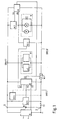
- the circuit arrangement according to the invention contains a first voltage sensor SE1, a second voltage sensor SE2, a controllable switching element M1, a controllable Resistor element M2 and a control circuit, which is a logic logic circuit L and a cut-off circuit A contains.
- the circuit arrangement has a connection terminal 1, which is connected to the positive pole of a secondary battery B. is, and a ground terminal 2, which is connected to the negative pole of the secondary battery B. is.
- a mechanical switch S1 connects the ground terminal 2 to a ground line section GND2.
- the first voltage sensor SE1 is with its Supply voltage and sensor connections between one with the connection terminal 1 connected supply voltage line and the ground line section GND2 switched.
- the logic logic circuit L is with its supply voltage connections also between the supply voltage line and the ground line section GND2 switched.
- the controllable switch element M1 is located between the GND2 ground line section and another ground line section GND3, and has a control input to which an output signal U4 the logic logic circuit L can be supplied.
- a series connection from the controllable resistance element M2 and first consumers V is between the Supply voltage line and the further ground line section GND3 switched. In parallel, there are other consumers V1 and the supply voltage connections the cut-off circuit A switched.
- the second voltage sensor SE2 is with its Supply voltage and sensor connections parallel to the first consumers V switched.
- the outputs of the first voltage sensor SE1, the second voltage sensor SE2, and possibly further sensors SE3 are with corresponding inputs of the logical logic circuit L connected.
- the output of the first voltage sensor SE1 is also connected to a first input of the cut-off circuit A.
- a second input of the cut-off circuit A is at the connection point between the controllable resistance element M2 and the first consumers V connected.
- the control output of the cut-off circuit A is connected to the control input of the controllable resistance elements M2 connected.
- the mechanical switch S1 is closed to switch on the system.
- the first voltage sensor SE1 provides an output signal U2 which has the value HIGH assumes, and thereby indicates that the secondary battery voltage UBATT is above a Switch-off voltage UBATTmin is.
- the second voltage sensor SE2 supplies an output signal U1, which takes the value LOW, and thereby indicates that the supply voltage UV of the first consumer V is below a threshold UVmin.
- the Output signals U2 and U1 of the first and second voltage sensors are applied to the corresponding inputs of the logic logic circuit L, which among these Conditions provides the output signal U4 with the value HIGH that the controllable Switch element M1 is supplied.
- the controllable switch element M1 the ground line section GND2 with the further ground line section GND3 connected so that the other consumers V1, the cut-off circuit A and the second voltage sensor SE2 supplied with voltage by the secondary battery B. become.
- U2 of the first voltage sensor SE1 which assumes the value HIGH, causes the Regulation circuit A turns on the controllable resistance element M2, so that also the first consumer V via the controllable resistance element M2 with voltage be supplied.
- the supply voltage UV corresponds to the first consumer V practically the supply voltage UBATT of the secondary battery B, and is therefore above a threshold UVmin. Therefore, the second voltage sensor delivers SE2 an output signal U1, which assumes the value HIGH. So that’s now System ready for operation.
- the secondary battery voltage UBATT decreases, and reaches the cut-off voltage UBATTmin.
- the output signal U2 then changes of the first voltage sensor SE1 from HIGH to LOW.
- the cut-off circuit reduces A the supply voltage UV according to a defined time course the first consumer V by the controllable resistance element M2 as a function of time controls so that its resistance value increases over time. Thereby the supply voltage UV of the first consumer V is reduced to one Threshold UVmin.
- the output voltage changes when this threshold value UVmin is reached of the second voltage sensor SE2 from HIGH to LOW.
- the first voltage sensor SE1 and the logic logic circuit L so can be designed so that their supply currents are in the microampere range through the voltage sensor SE1 and the logic logic circuit L the secondary battery B discharge only so slowly that it is normally expected can that the secondary battery B by the user in time before a deep discharge is recharged.
- the mechanical switch S1 also the first voltage sensor SE1 and the logic logic circuit L be separated from the secondary battery B, so that thereby secure protection against Deep discharge of the secondary battery B can be achieved.
- the system can be operated using a Power supply be put back into operation.
- the mechanical Switch S1 By operating the mechanical Switch S1, the consumers can only be operated again if in the meantime a charger has charged the secondary battery B so far that the Secondary battery voltage UBATT has risen above the value UBATTmin, and thus the first voltage sensor SE1 again has an output signal U2 with the value HIGH supplies.
- this can System even when the secondary battery is discharged using an appropriately designed one Charging power supply N operated.
- the logic logic circuit L a further input to which the output signal U3 of the charging power supply N is supplied becomes.
- the output signal takes of the charging power supply to the value HIGH.
- the mechanical switch is closed S1 thereby becomes the output signal U4 of the logic logic circuit L again set to the value HIGH, so that the controllable switching element M1 is closed.
- the system is thus operated with the current supplied by the charging power supply N.
- the secondary battery B can be recharged. After more complete Charging the secondary battery B turns off the charging power supply N.
- the output signal U3 of the charging power supply N changes from HIGH to LOW.
- the output signal U4 of the logical Logic circuit L only assumes the value LOW, and thus that controllable switching element M1 opens when each of the three signals U1, U2 and U3 the Assumes LOW value. Therefore, the logic logic circuit L can be used as an OR gate be executed. In another version of the logic logic circuit other values can be selected accordingly for the signals U1, U2 and U3.
- Controllable switching element M1 finds, for example, a relay or a MOS-FET Use.
- the controllable resistance element M2 is preferably a MOS-FET.
- Switching threshold of the first voltage sensor SE1 adjustable. This allows the circuit arrangement can be set to different switch-off voltages, and is therefore adaptable to different types of secondary batteries, solar cells, etc.
- a modified logic logic circuit L has further inputs, the output signals of further sensors SE3 can be fed to them. Thereby additional shutdown conditions can be implemented, for example a temperature shutdown, which prevents overheating of a consumer.
- each consumer V together by the Regulation circuit A regulated.
- each consumer to be curtailed has its own curtailment circuit and its own controllable resistance element is provided.
- the regulation circuit A has an operational amplifier OP1, whose inverting input is the supply voltage UV first consumer V can be fed. Between the non-inverting input of the Operational amplifier OP1 and the further ground line section GND3 is a resistor R1 and, in parallel, a capacitor C1 and a series connection of one controllable switch M3 and a reference voltage source UREF switched.
- the controllable switch M3 has a control input which is connected to the output of the first Voltage sensor SE1 is connected.
- the output U5 of the operational amplifier OP1 is connected to the control input of the controllable resistance element M2.
- the controllable switch M3 is, for example, by a relay or by a MOSFET realized.
- the controllable switch M3 is closed when the system is ready for operation and connects the non-inverting input of the operational amplifier OP1 with the Reference voltage source UREF.
- the one at the inverting input Supply voltage UV of the first consumer V to the voltage of the reference voltage source UREF are regulated.
- Changes the output signal of the first Voltage sensor SE1 from HIGH to LOW the controllable switch M3 is opened.
- the capacitor C1 discharges, which was previously controllable when the closed one Switch M3 was charged to the reference voltage, through resistor R1.
- a time-decreasing reference voltage is generated. This leads to an also time-decreasing output signal U5, and the supply voltage UV of the first consumer V is correspondingly controlled by the controllable resistance element M2 with increasing discharge of the capacitor C1 to zero curtailed.
- Another variant of the cut-off circuit is the reference voltage source UREF omitted. Instead, the controllable switch M3 will not inverting input of the operational amplifier OP1 directly the secondary battery voltage UBATT fed. This variant is used in cases where the first consumer V does not necessarily have a regulated supply voltage UV must be operated.
- the cut-off circuit consists of only one Microcontroller. If the first voltage sensor SE1 with its output signal U2 triggers the curtailment, the voltage at the output U5 of the microcontroller in small steps reduced to thereby by means of the controllable resistance element M2 to regulate the first consumers V.
- a current, speed, Brightness or volume control can be implemented.
- a control circuit can be provided instead of a cut-off circuit the controllable resistance element M2 in the presence of a switch-off condition Time-changing signal U5, which is independent of the supply voltage UV is the first consumer V, so the current through the first consumer V to decrease.
Landscapes
- Engineering & Computer Science (AREA)
- Power Engineering (AREA)
- Charge And Discharge Circuits For Batteries Or The Like (AREA)
- Control And Safety Of Cranes (AREA)
- Protection Of Static Devices (AREA)
- Supply And Distribution Of Alternating Current (AREA)
- Control Of Steam Boilers And Waste-Gas Boilers (AREA)
- Spinning Or Twisting Of Yarns (AREA)
- Direct Current Feeding And Distribution (AREA)
Description
- Fig. 1
- ein Blockschaltbild einer erfindungsgemäßen Schaltungsanordnung;
- Fig. 2
- eine Ausführung der Abregelungsschaltung nach Fig. 1.
Claims (20)
- Verfahren zum Abschalten eines elektrischen Geräts mit mehreren an eine Spannungsquelle angeschlossenen Verbrauchern, bei dem der von der Spannungsquelle gelieferte Strom kontinuierlich oder schrittweise verringert wird, worin in einem ersten Schritt der von der Spannungsquelle (B) an mindestens einen ersten Verbraucher (V) gelieferte Strom bis auf Null verringert wird, und danach in einem zweiten Schritt der von der Spannungsquelle (B) an mindestens einen weiteren Verbraucher (V1) gelieferte Strom abgeschaltet wird.
- Verfahren nach Anspruch 1, dadurch gekennzeichnet, daß der an den oder die ersten Verbraucher (V) gelieferte Strom bis auf einen voreinstellbaren Wert, beispielsweise Null, verringert wird.
- Verfahren nach Anspruch 1 oder 2, dadurch gekennzeichnet, daß gleichzeitig mit dem Abschalten des oder der weiteren Verbraucher(s) (V1) auch der oder die erste(n) Verbraucher (V) abgeschaltet wird (werden).
- Verfahren nach einem der vorhergehenden Ansprüche, dadurch gekennzeichnet, daß die Spannung der Spannungsquelle (B) durch einen ersten Spannungssensor (SE1) bestimmt wird, der ein Ausgangssignal (U2) liefert, und daß der an den oder die ersten Verbraucher (V) gelieferte Strom verringert wird, wenn die Spannung (UBATT) der Spannungsquelle (B) einen Schwellwert unterschreitet.
- Verfahren nach einem der vorhergehenden Ansprüche, dadurch gekennzeichnet, daß mindestens ein weiterer Sensor (SE3), insbesondere ein Temperatursensor vorhanden ist, der ein Ausgangssignal liefert, und daß der an den oder die ersten Verbraucher (V) gelieferte Strom verringert wird, wenn das Ausgangssignal des weiteren Sensors (SE3) einen Schwellwert über- oder unterschreitet.
- Verfahren nach Anspruch 4 oder 5, dadurch gekennzeichnet, daß nach Ablauf einer bestimmten Zeit nach Beginn der Verringerung des an den oder die ersten Verbraucher (V) gelieferten Stroms zumindest der an die weiteren Verbraucher (V1) gelieferte Strom abgeschaltet wird.
- Verfahren nach Anspruch 4 oder 5, dadurch gekennzeichnet, daß die Spannung am ersten Verbraucher (V) durch einen zweiten Spannungssensor (SE2) bestimmt wird, der ein Ausgangssignal (U1) liefert, und daß zumindest der an die weiteren Verbraucher (V1) gelieferte Strom abgeschaltet wird, wenn die Spannung am ersten Verbraucher (V) einen Schwellwert unterschreitet.
- Schaltungsanordnung zur Abschaltung mindestens eines an eine Spannungsquelle (B) angeschlossenen Verbrauchers (V) mit einem steuerbaren Widerstandselement (M2) und einer das steuerbare Widerstandselement (M2) ansteuernden Regelschaltung, wobei die Schaltungsanordnung ferner ein steuerbares Schaltelement (M1) zur Abschaltung mindestens eines weiteren Verbrauchers (V1) aufweist, das durch die Regelschaltung ansteuerbar ist, und die Regelschaltung so ausgebildet ist, daß erst nach Verringerung bis auf Null des durch mindestens einen ersten Verbraucher (V) fließenden Stroms der oder die weitere(n) Verbraucher (V1) durch Ansteuerung des steuerbaren Schaltelements (M1) abschaltbar ist (sind).
- Schaltungsanordnung nach Anspruch 8, dadurch gekennzeichnet, daß die Regelschaltung so ausgebildet ist, daß erst nach Verringerung des durch den oder die ersten Verbraucher (V) fließenden Stroms der oder die ersten Verbraucher (V) durch Ansteuerung des steuerbaren Schaltelements (M1) abschaltbar ist (sind).
- Schaltungsanordnung nach Anspruch 8 oder 9, dadurch gekennzeichnet, daß die Regelschaltung eine logische Verknüpfungsschaltung (L) und eine Abregelungsschaltung (A) enthält, denen ein Ausgangssignal (U2) eines ersten Spannungssensors (SE1) zur Bestimmung der Spannung (UBATT) der Spannungsquelle (B) zuführbar ist.
- Schaltungsanordnung nach Anspruch 10, dadurch gekennzeichnet, daß der logischen Verknüpfungsschaltung (L) ein Ausgangssignal (U1) eines zweiten Spannungssensors (SE2) zur Bestimmung der an dem oder den ersten Verbraucher(n) (V) anliegenden Spannung (UV) zuführbar ist.
- Schaltungsanordnung nach Anspruch 10 oder 11, dadurch gekennzeichnet, daß die Spannungsquelle (B) eine Batterie oder eine mindestens eine Solarzelle enthaltende Gleichspannungsquelle ist.
- Schaltungsanordnung nach Anspruch 12, dadurch gekennzeichnet, daß der logischen Verknüpfungsschaltung (L) ein Ausgangssignal (U3) eines Ladenetzteils (N) zum Laden einer Sekundärbatterie zuführbar ist.
- Schaltungsanordnung nach einem der Ansprüche 8 bis 13, dadurch gekenneichnet, daß der Regelschaltung ein Ausgangssignal mindestens eines weiteren Sensors (SE3), insbesondere eines Temperatursensors, zuführbar ist.
- Schaltungsanordnung nach einem der vorangehenden Ansprüche 8 bis 14, dadurch gekennzeichnet, daß die Regelschaltung eine Zeitschaltung enthält, die nach einer bestimmten Zeit nach Beginn der Verringerung des Stroms die Verbraucher abschaltet.
- Schaltungsanordnung nach einem der Ansprüche 8 bis 15, dadurch gekennzeichnet, daß das steuerbare Widerstandselement (M2) ein MOSFET ist, der von der Abregelungsschaltung (A) ansteuerbar ist, und daß das steuerbare Schaltelement (M1) ein MOSFET oder ein Relais ist, das von der logischen Verknüpfungsschaltung (L) ansteuerbar ist.
- Schaltungsanordnung nach einem der Ansprüche 10 bis 16, dadurch gekennzeichnet, daß die logische Verknüpfungsschaltung (L) ein ODER-Gatter aufweist.
- Schaltungsanordnung nach einem der Ansprüche 10 bis 17, dadurch gekennzeichnet, daß der Abregelungsschaltung (A) ein Signal zuführbar ist, das der an den ersten Verbrauchern (V) anliegenden Spannung (UV) entspricht.
- Schaltungsanordnung nach Anspruch 18, dadurch gekennzeichnet, daß die Abregelungsschaltung (A) einen Operationsverstärker (OP1) enthält, dem das der an den ersten Verbrauchern (V) anliegenden Spannung (UV) entsprechende Signal sowie eine Referenzspannung (UREF; UBATT) zuführbar ist, und dessen Ausgangssignal (U5) dem steuerbaren Widerstandselement (M2) zuführbar ist.
- Schaltungsanordnung nach Anspruch 19, dadurch gekennzeichnet, daß die Abregelungsschaltung (A) einen steuerbaren Schalter (M3) enthält, der durch den ersten Spannungssensor (SE1) steuerbar ist, und daß durch den steuerbaren Schalter (M3) statt der Referenzspannung (UREF) eine sich verändernde Spannung, insbesondere die Spannung eines sich über einen Widerstand (R1) entladenden Kondensators (C1), dem Operationsverstärker (OP1) zuführbar ist.
Applications Claiming Priority (3)
| Application Number | Priority Date | Filing Date | Title |
|---|---|---|---|
| DE19637574 | 1996-09-14 | ||
| DE19637574A DE19637574A1 (de) | 1996-09-14 | 1996-09-14 | Verfahren und Anordnung zur Abschaltung von Verbrauchern |
| PCT/EP1997/004664 WO1998011644A1 (de) | 1996-09-14 | 1997-08-27 | Verfahren und anordnung zur abschaltung von verbrauchern |
Publications (2)
| Publication Number | Publication Date |
|---|---|
| EP0925626A1 EP0925626A1 (de) | 1999-06-30 |
| EP0925626B1 true EP0925626B1 (de) | 2001-11-14 |
Family
ID=7805691
Family Applications (1)
| Application Number | Title | Priority Date | Filing Date |
|---|---|---|---|
| EP97940132A Expired - Lifetime EP0925626B1 (de) | 1996-09-14 | 1997-08-27 | Verfahren und anordnung zur abschaltung von verbrauchern |
Country Status (8)
| Country | Link |
|---|---|
| US (1) | US6188142B1 (de) |
| EP (1) | EP0925626B1 (de) |
| JP (1) | JP3789488B2 (de) |
| CN (1) | CN1098553C (de) |
| AT (1) | ATE208968T1 (de) |
| DE (2) | DE19637574A1 (de) |
| ES (1) | ES2167788T3 (de) |
| WO (1) | WO1998011644A1 (de) |
Families Citing this family (19)
| Publication number | Priority date | Publication date | Assignee | Title |
|---|---|---|---|---|
| DE19849493C1 (de) | 1998-10-27 | 1999-12-02 | Daimler Chrysler Ag | Verfahren zur Erfassung der Ladebilanz von Akkumulatoren |
| EP1148681B1 (de) | 2000-04-20 | 2005-12-07 | Nokia Corporation | Verfahren zur Übertragung von Ressourceninformation |
| US7139792B1 (en) * | 2000-09-29 | 2006-11-21 | Intel Corporation | Mechanism for locking client requests to a particular server |
| JP2003164066A (ja) * | 2001-11-21 | 2003-06-06 | Hitachi Koki Co Ltd | 電池パック |
| ATE330233T1 (de) * | 2002-10-08 | 2006-07-15 | Oticon As | Verfahren zur stromverwaltung in einer batteriebetriebenen einrichtung und batteriebetriebene einrichutng |
| US7782018B2 (en) * | 2007-09-10 | 2010-08-24 | Maxim Integrated Products, Inc. | Adaptive current limiting for any power source with output equivalent series resistance |
| TWI434921B (zh) | 2009-06-17 | 2014-04-21 | Danisco Us Inc | 從生物異戊二烯組合物製造燃料成分之方法及系統 |
| DE102010028638A1 (de) | 2010-05-05 | 2011-11-10 | BSH Bosch und Siemens Hausgeräte GmbH | Verfahren zum Versorgen eines elektrischen Hausgeräts aus einem Niederspannungsversorgungsnetz |
| JP4775516B1 (ja) | 2011-03-14 | 2011-09-21 | オムロン株式会社 | 制御装置、制御方法、プログラム、記録媒体 |
| JP5888019B2 (ja) | 2011-12-12 | 2016-03-16 | オムロン株式会社 | 制御装置、制御方法、プログラムおよび記録媒体 |
| CN103944149B (zh) * | 2014-04-16 | 2016-09-14 | 南车株洲电力机车有限公司 | 一种蓄电池馈电保护电路 |
| EP3124099A1 (de) | 2015-07-30 | 2017-02-01 | Gambro Lundia AB | Acrylnitril-basierte membran mit verbesserter leistung |
| CN105375858B (zh) * | 2015-11-19 | 2017-12-26 | 珠海格力电器股份有限公司 | 光伏系统控制方法和装置 |
| EP3296010B1 (de) | 2016-09-14 | 2023-04-26 | Gambro Lundia AB | Auf acrylonitril basierende membran mit niedriger thrombogenität |
| EP3548164A1 (de) | 2016-11-29 | 2019-10-09 | Gambro Lundia AB | Membran zur adsorption von bakterien |
| KR102073033B1 (ko) * | 2017-05-16 | 2020-02-04 | 가부시키가이샤다쓰미료키 | 부하 시스템, 부하 시험 장치 및 통신 단말 |
| EP3661838A4 (de) * | 2017-08-01 | 2021-03-31 | Cummins Inc. | Steuerlogikschaltung zur verbindung von mehreren hohen seitenlasten in einem motorsteuermodul |
| CN113303702B (zh) * | 2020-02-26 | 2023-02-24 | 江苏美的清洁电器股份有限公司 | 吸尘器电路系统及其供电控制方法及吸尘器 |
| JP7745480B2 (ja) * | 2022-02-28 | 2025-09-29 | 本田技研工業株式会社 | 電源システム |
Family Cites Families (12)
| Publication number | Priority date | Publication date | Assignee | Title |
|---|---|---|---|---|
| FR2445642A1 (fr) * | 1978-12-29 | 1980-07-25 | Radiotechnique Compelec | Agencement de securite en cas de chute d'une tension d'alimentation continue |
| US4703247A (en) | 1985-07-19 | 1987-10-27 | Sanyo Electric Co., Ltd. | Battery apparatus for an electric shaver |
| DE3611484C2 (de) | 1986-04-05 | 1994-06-09 | Ceag Licht & Strom | Schaltungsanordnung für eine tragbare Leuchte |
| US4949215A (en) * | 1988-08-26 | 1990-08-14 | Borg-Warner Automotive, Inc. | Driver for high speed solenoid actuator |
| US5204992A (en) * | 1990-11-30 | 1993-04-20 | General Motors Corporation | Motor vehicle battery discharge load current control |
| DE4116318A1 (de) * | 1991-05-15 | 1992-11-19 | Aeg Westinghouse Transport | Anordnung zum schutz von akkumulatoren gegen tiefentladung |
| DE4131981A1 (de) * | 1991-09-26 | 1993-04-01 | Braun Ag | Batteriebetriebenes geraet |
| JPH05205781A (ja) * | 1992-01-28 | 1993-08-13 | Sanyo Electric Co Ltd | 電池の過放電防止装置 |
| DE4241066C1 (de) * | 1992-12-05 | 1994-01-13 | Braun Ag | Automatische Laststromrückregelung |
| JP3222999B2 (ja) * | 1993-08-20 | 2001-10-29 | 三洋電機株式会社 | 二次電池の過放電防止回路 |
| US5804894A (en) * | 1996-08-16 | 1998-09-08 | Telxon Corporation | Low voltage battery pack monitoring circuit with adjustable set points |
| US6040682A (en) * | 1999-02-02 | 2000-03-21 | The United States Of America As Represented By The Secretary Of The Navy | Circuit for preventing battery damage |
-
1996
- 1996-09-14 DE DE19637574A patent/DE19637574A1/de not_active Withdrawn
-
1997
- 1997-08-27 WO PCT/EP1997/004664 patent/WO1998011644A1/de not_active Ceased
- 1997-08-27 EP EP97940132A patent/EP0925626B1/de not_active Expired - Lifetime
- 1997-08-27 JP JP51319698A patent/JP3789488B2/ja not_active Expired - Lifetime
- 1997-08-27 AT AT97940132T patent/ATE208968T1/de not_active IP Right Cessation
- 1997-08-27 US US09/254,313 patent/US6188142B1/en not_active Expired - Lifetime
- 1997-08-27 DE DE59705411T patent/DE59705411D1/de not_active Expired - Lifetime
- 1997-08-27 CN CN97197856A patent/CN1098553C/zh not_active Expired - Lifetime
- 1997-08-27 ES ES97940132T patent/ES2167788T3/es not_active Expired - Lifetime
Also Published As
| Publication number | Publication date |
|---|---|
| US6188142B1 (en) | 2001-02-13 |
| CN1098553C (zh) | 2003-01-08 |
| CN1230303A (zh) | 1999-09-29 |
| ATE208968T1 (de) | 2001-11-15 |
| WO1998011644A1 (de) | 1998-03-19 |
| HK1021263A1 (en) | 2000-06-02 |
| DE19637574A1 (de) | 1998-03-26 |
| EP0925626A1 (de) | 1999-06-30 |
| JP2001500355A (ja) | 2001-01-09 |
| ES2167788T3 (es) | 2002-05-16 |
| JP3789488B2 (ja) | 2006-06-21 |
| DE59705411D1 (de) | 2001-12-20 |
Similar Documents
| Publication | Publication Date | Title |
|---|---|---|
| EP0925626B1 (de) | Verfahren und anordnung zur abschaltung von verbrauchern | |
| EP0568655B1 (de) | Vorrichtung zur spannungsversorgung in einem kraftfahrzeug | |
| DE69124450T2 (de) | NI-Cad Batterie-Laderegler | |
| DE69733854T2 (de) | Schaltung zur Auswahl und Bestimmung eines Master-Batteriepakets in einem Computersystem | |
| DE69839115T2 (de) | Batterieschutzsystem | |
| DE102007018761B4 (de) | Energieversorgungssteuerung | |
| EP2435279B1 (de) | Bordnetz für ein fahrzeug sowie steuervorrichtung für ein bordnetz | |
| DE69508746T2 (de) | Selbstkonfigurierendes Batterieladegerät mit Mehrfachfunktionen als Versorgungsspannungsregler für batteriebetriebene Geräte | |
| DE102015008603A1 (de) | Batteriepack und Verfahren zum Steuern desselben | |
| DE69615774T2 (de) | Steuerungsvorrichtung für Wechselstromgenerator | |
| DE602004007074T2 (de) | Unterbrechungsfreie Stromversorgung | |
| DE112010001323T5 (de) | Energieversorgungssteuerung und Steuerverfahren dafür | |
| DE102018125272A1 (de) | Vorrichtung und Verfahren zum Entladen eines Zwischenkreiskondensators, Stromrichter und Fahrzeug | |
| WO2019192819A1 (de) | Verfahren und vorrichtung zum betreiben eines kraftfahrzeugs | |
| DE69400033T2 (de) | Konstantstrom-Batterieladegerät mit Zusatzstromversorgungsaussgang für tragbares Gerät. | |
| EP1299933B1 (de) | Elektronische schaltung für ein energieversorgungsgerät, insbesondere für ein ladegerät für akkumulatoren | |
| EP2553257B1 (de) | Bordnetz für ein fahrzeug sowie steuervorrichtung zum steuern eines stromflusses in einem bordnetz eines fahrzeugs | |
| EP4631769A1 (de) | Verfahren zum betreiben einer elektrischen leistungsversorgungsvorrichtung, abschaltsteuervorrichtung und leistungsversorgungsvorrichtung | |
| EP4631767A1 (de) | Verfahren zum betreiben einer elektrischen leistungsversorgungsvorrichtung, abschaltsteuervorrichtung, abschalteinrichtung, und leistungsversorgungsvorrichtung | |
| DE102014108601A1 (de) | Verfahren zum Anschließen mehrerer Batterieeinheiten an einen zweipoligen Eingang eines bidirektionalen Batteriewandlers sowie bidirektionaler Batteriewandler und Photovoltaikwechselrichter | |
| WO2018103946A1 (de) | Verfahren, maschinenlesbares speichermedium und elektronische steuereinheit zum betrieb eines elektrischen energiespeichersystems sowie entsprechendes elektrisches energiespeichersystem | |
| DE60222767T2 (de) | Stromversorgungseinrichtung | |
| EP2230135B1 (de) | Vorrichtung | |
| DE102012218596B4 (de) | Steuereinheit für ein Bordnetz, Bordnetz und Verfahren zum Betreiben eines Bordnetzes | |
| EP2720335B1 (de) | Schaltung zur Steuerung der Energieversorgung eines elektrischen Geräts sowie elektrisches Gerät mit einer Schaltung |
Legal Events
| Date | Code | Title | Description |
|---|---|---|---|
| PUAI | Public reference made under article 153(3) epc to a published international application that has entered the european phase |
Free format text: ORIGINAL CODE: 0009012 |
|
| 17P | Request for examination filed |
Effective date: 19990309 |
|
| AK | Designated contracting states |
Kind code of ref document: A1 Designated state(s): AT BE CH DE DK ES FI FR GB GR IE IT LI LU MC NL PT SE |
|
| RAP1 | Party data changed (applicant data changed or rights of an application transferred) |
Owner name: BRAUN GMBH |
|
| GRAG | Despatch of communication of intention to grant |
Free format text: ORIGINAL CODE: EPIDOS AGRA |
|
| 17Q | First examination report despatched |
Effective date: 20001122 |
|
| GRAG | Despatch of communication of intention to grant |
Free format text: ORIGINAL CODE: EPIDOS AGRA |
|
| GRAH | Despatch of communication of intention to grant a patent |
Free format text: ORIGINAL CODE: EPIDOS IGRA |
|
| ITF | It: translation for a ep patent filed | ||
| GRAH | Despatch of communication of intention to grant a patent |
Free format text: ORIGINAL CODE: EPIDOS IGRA |
|
| GRAA | (expected) grant |
Free format text: ORIGINAL CODE: 0009210 |
|
| AK | Designated contracting states |
Kind code of ref document: B1 Designated state(s): AT BE CH DE DK ES FI FR GB GR IE IT LI LU MC NL PT SE |
|
| PG25 | Lapsed in a contracting state [announced via postgrant information from national office to epo] |
Ref country code: IE Free format text: LAPSE BECAUSE OF FAILURE TO SUBMIT A TRANSLATION OF THE DESCRIPTION OR TO PAY THE FEE WITHIN THE PRESCRIBED TIME-LIMIT Effective date: 20011114 Ref country code: GR Free format text: LAPSE BECAUSE OF FAILURE TO SUBMIT A TRANSLATION OF THE DESCRIPTION OR TO PAY THE FEE WITHIN THE PRESCRIBED TIME-LIMIT Effective date: 20011114 Ref country code: FI Free format text: LAPSE BECAUSE OF FAILURE TO SUBMIT A TRANSLATION OF THE DESCRIPTION OR TO PAY THE FEE WITHIN THE PRESCRIBED TIME-LIMIT Effective date: 20011114 |
|
| REF | Corresponds to: |
Ref document number: 208968 Country of ref document: AT Date of ref document: 20011115 Kind code of ref document: T |
|
| REG | Reference to a national code |
Ref country code: CH Ref legal event code: EP |
|
| GBT | Gb: translation of ep patent filed (gb section 77(6)(a)/1977) |
Effective date: 20011114 |
|
| REG | Reference to a national code |
Ref country code: IE Ref legal event code: FG4D Free format text: GERMAN |
|
| REF | Corresponds to: |
Ref document number: 59705411 Country of ref document: DE Date of ref document: 20011220 |
|
| REG | Reference to a national code |
Ref country code: GB Ref legal event code: IF02 |
|
| PG25 | Lapsed in a contracting state [announced via postgrant information from national office to epo] |
Ref country code: SE Free format text: LAPSE BECAUSE OF FAILURE TO SUBMIT A TRANSLATION OF THE DESCRIPTION OR TO PAY THE FEE WITHIN THE PRESCRIBED TIME-LIMIT Effective date: 20020214 Ref country code: PT Free format text: LAPSE BECAUSE OF FAILURE TO SUBMIT A TRANSLATION OF THE DESCRIPTION OR TO PAY THE FEE WITHIN THE PRESCRIBED TIME-LIMIT Effective date: 20020214 Ref country code: DK Free format text: LAPSE BECAUSE OF FAILURE TO SUBMIT A TRANSLATION OF THE DESCRIPTION OR TO PAY THE FEE WITHIN THE PRESCRIBED TIME-LIMIT Effective date: 20020214 |
|
| REG | Reference to a national code |
Ref country code: ES Ref legal event code: FG2A Ref document number: 2167788 Country of ref document: ES Kind code of ref document: T3 |
|
| REG | Reference to a national code |
Ref country code: IE Ref legal event code: FD4D |
|
| PG25 | Lapsed in a contracting state [announced via postgrant information from national office to epo] |
Ref country code: LU Free format text: LAPSE BECAUSE OF NON-PAYMENT OF DUE FEES Effective date: 20020827 |
|
| PG25 | Lapsed in a contracting state [announced via postgrant information from national office to epo] |
Ref country code: ES Free format text: LAPSE BECAUSE OF NON-PAYMENT OF DUE FEES Effective date: 20020828 |
|
| PG25 | Lapsed in a contracting state [announced via postgrant information from national office to epo] |
Ref country code: LI Free format text: LAPSE BECAUSE OF NON-PAYMENT OF DUE FEES Effective date: 20020831 Ref country code: CH Free format text: LAPSE BECAUSE OF NON-PAYMENT OF DUE FEES Effective date: 20020831 Ref country code: BE Free format text: LAPSE BECAUSE OF NON-PAYMENT OF DUE FEES Effective date: 20020831 |
|
| PLBE | No opposition filed within time limit |
Free format text: ORIGINAL CODE: 0009261 |
|
| STAA | Information on the status of an ep patent application or granted ep patent |
Free format text: STATUS: NO OPPOSITION FILED WITHIN TIME LIMIT |
|
| 26N | No opposition filed | ||
| BERE | Be: lapsed |
Owner name: *BRAUN G.M.B.H. Effective date: 20020831 |
|
| PG25 | Lapsed in a contracting state [announced via postgrant information from national office to epo] |
Ref country code: MC Free format text: LAPSE BECAUSE OF NON-PAYMENT OF DUE FEES Effective date: 20030301 |
|
| REG | Reference to a national code |
Ref country code: CH Ref legal event code: PL |
|
| REG | Reference to a national code |
Ref country code: ES Ref legal event code: FD2A Effective date: 20030912 |
|
| PG25 | Lapsed in a contracting state [announced via postgrant information from national office to epo] |
Ref country code: IT Free format text: LAPSE BECAUSE OF NON-PAYMENT OF DUE FEES;WARNING: LAPSES OF ITALIAN PATENTS WITH EFFECTIVE DATE BEFORE 2007 MAY HAVE OCCURRED AT ANY TIME BEFORE 2007. THE CORRECT EFFECTIVE DATE MAY BE DIFFERENT FROM THE ONE RECORDED. Effective date: 20050827 |
|
| PGFP | Annual fee paid to national office [announced via postgrant information from national office to epo] |
Ref country code: AT Payment date: 20080826 Year of fee payment: 12 |
|
| PG25 | Lapsed in a contracting state [announced via postgrant information from national office to epo] |
Ref country code: AT Free format text: LAPSE BECAUSE OF NON-PAYMENT OF DUE FEES Effective date: 20090827 |
|
| PGFP | Annual fee paid to national office [announced via postgrant information from national office to epo] |
Ref country code: FR Payment date: 20100819 Year of fee payment: 14 |
|
| REG | Reference to a national code |
Ref country code: FR Ref legal event code: ST Effective date: 20120430 |
|
| PG25 | Lapsed in a contracting state [announced via postgrant information from national office to epo] |
Ref country code: FR Free format text: LAPSE BECAUSE OF NON-PAYMENT OF DUE FEES Effective date: 20110831 |
|
| PGFP | Annual fee paid to national office [announced via postgrant information from national office to epo] |
Ref country code: NL Payment date: 20160805 Year of fee payment: 20 |
|
| PGFP | Annual fee paid to national office [announced via postgrant information from national office to epo] |
Ref country code: GB Payment date: 20160725 Year of fee payment: 20 Ref country code: DE Payment date: 20160831 Year of fee payment: 20 |
|
| REG | Reference to a national code |
Ref country code: DE Ref legal event code: R071 Ref document number: 59705411 Country of ref document: DE |
|
| REG | Reference to a national code |
Ref country code: NL Ref legal event code: MK Effective date: 20170826 |
|
| REG | Reference to a national code |
Ref country code: GB Ref legal event code: PE20 Expiry date: 20170826 |
|
| PG25 | Lapsed in a contracting state [announced via postgrant information from national office to epo] |
Ref country code: GB Free format text: LAPSE BECAUSE OF EXPIRATION OF PROTECTION Effective date: 20170826 |