EP0925102B1 - Method and apparatus for the continuous extrusion of block elements - Google Patents
Method and apparatus for the continuous extrusion of block elements Download PDFInfo
- Publication number
- EP0925102B1 EP0925102B1 EP97940735A EP97940735A EP0925102B1 EP 0925102 B1 EP0925102 B1 EP 0925102B1 EP 97940735 A EP97940735 A EP 97940735A EP 97940735 A EP97940735 A EP 97940735A EP 0925102 B1 EP0925102 B1 EP 0925102B1
- Authority
- EP
- European Patent Office
- Prior art keywords
- barrel
- die
- screw
- core
- extrusion device
- Prior art date
- Legal status (The legal status is an assumption and is not a legal conclusion. Google has not performed a legal analysis and makes no representation as to the accuracy of the status listed.)
- Expired - Lifetime
Links
- 238000001125 extrusion Methods 0.000 title claims abstract description 25
- 238000000034 method Methods 0.000 title claims abstract description 17
- 239000000463 material Substances 0.000 claims abstract description 49
- 238000001816 cooling Methods 0.000 claims abstract description 12
- 238000010438 heat treatment Methods 0.000 claims abstract description 6
- 239000011230 binding agent Substances 0.000 claims description 12
- 239000000203 mixture Substances 0.000 claims description 12
- 239000011347 resin Substances 0.000 claims description 9
- 229920005989 resin Polymers 0.000 claims description 9
- 239000002131 composite material Substances 0.000 claims description 8
- 238000002156 mixing Methods 0.000 claims description 5
- 239000007787 solid Substances 0.000 claims description 4
- 238000011144 upstream manufacturing Methods 0.000 claims description 2
- 206010001497 Agitation Diseases 0.000 claims 1
- 238000004891 communication Methods 0.000 claims 1
- 238000012544 monitoring process Methods 0.000 claims 1
- OKTJSMMVPCPJKN-UHFFFAOYSA-N Carbon Chemical compound [C] OKTJSMMVPCPJKN-UHFFFAOYSA-N 0.000 abstract description 11
- 229910052799 carbon Inorganic materials 0.000 abstract description 3
- -1 polyethylene Polymers 0.000 description 7
- XLYOFNOQVPJJNP-UHFFFAOYSA-N water Substances O XLYOFNOQVPJJNP-UHFFFAOYSA-N 0.000 description 6
- 239000004698 Polyethylene Substances 0.000 description 5
- 229920000573 polyethylene Polymers 0.000 description 5
- 239000000498 cooling water Substances 0.000 description 4
- 235000012438 extruded product Nutrition 0.000 description 4
- 239000000047 product Substances 0.000 description 4
- 238000004519 manufacturing process Methods 0.000 description 3
- 238000002844 melting Methods 0.000 description 3
- 230000008018 melting Effects 0.000 description 3
- JOYRKODLDBILNP-UHFFFAOYSA-N Ethyl urethane Chemical compound CCOC(N)=O JOYRKODLDBILNP-UHFFFAOYSA-N 0.000 description 2
- 230000004323 axial length Effects 0.000 description 2
- 230000010006 flight Effects 0.000 description 2
- 239000000155 melt Substances 0.000 description 2
- VNWKTOKETHGBQD-UHFFFAOYSA-N methane Chemical compound C VNWKTOKETHGBQD-UHFFFAOYSA-N 0.000 description 2
- 230000002411 adverse Effects 0.000 description 1
- 238000013019 agitation Methods 0.000 description 1
- 230000015572 biosynthetic process Effects 0.000 description 1
- 239000007795 chemical reaction product Substances 0.000 description 1
- 238000010276 construction Methods 0.000 description 1
- 238000001914 filtration Methods 0.000 description 1
- 230000009969 flowable effect Effects 0.000 description 1
- 239000008187 granular material Substances 0.000 description 1
- 238000001746 injection moulding Methods 0.000 description 1
- 230000033001 locomotion Effects 0.000 description 1
- 239000011812 mixed powder Substances 0.000 description 1
- 229920000098 polyolefin Polymers 0.000 description 1
- 239000012254 powdered material Substances 0.000 description 1
- 229920001169 thermoplastic Polymers 0.000 description 1
- 239000004416 thermosoftening plastic Substances 0.000 description 1
- 230000000007 visual effect Effects 0.000 description 1
Images

Classifications
-
- B—PERFORMING OPERATIONS; TRANSPORTING
- B01—PHYSICAL OR CHEMICAL PROCESSES OR APPARATUS IN GENERAL
- B01D—SEPARATION
- B01D39/00—Filtering material for liquid or gaseous fluids
- B01D39/14—Other self-supporting filtering material ; Other filtering material
- B01D39/20—Other self-supporting filtering material ; Other filtering material of inorganic material, e.g. asbestos paper, metallic filtering material of non-woven wires
-
- B—PERFORMING OPERATIONS; TRANSPORTING
- B01—PHYSICAL OR CHEMICAL PROCESSES OR APPARATUS IN GENERAL
- B01D—SEPARATION
- B01D39/00—Filtering material for liquid or gaseous fluids
- B01D39/14—Other self-supporting filtering material ; Other filtering material
- B01D39/20—Other self-supporting filtering material ; Other filtering material of inorganic material, e.g. asbestos paper, metallic filtering material of non-woven wires
- B01D39/2055—Carbonaceous material
- B01D39/2058—Carbonaceous material the material being particulate
- B01D39/2062—Bonded, e.g. activated carbon blocks
-
- B—PERFORMING OPERATIONS; TRANSPORTING
- B01—PHYSICAL OR CHEMICAL PROCESSES OR APPARATUS IN GENERAL
- B01D—SEPARATION
- B01D39/00—Filtering material for liquid or gaseous fluids
- B01D39/14—Other self-supporting filtering material ; Other filtering material
- B01D39/20—Other self-supporting filtering material ; Other filtering material of inorganic material, e.g. asbestos paper, metallic filtering material of non-woven wires
- B01D39/2055—Carbonaceous material
-
- B—PERFORMING OPERATIONS; TRANSPORTING
- B29—WORKING OF PLASTICS; WORKING OF SUBSTANCES IN A PLASTIC STATE IN GENERAL
- B29C—SHAPING OR JOINING OF PLASTICS; SHAPING OF MATERIAL IN A PLASTIC STATE, NOT OTHERWISE PROVIDED FOR; AFTER-TREATMENT OF THE SHAPED PRODUCTS, e.g. REPAIRING
- B29C48/00—Extrusion moulding, i.e. expressing the moulding material through a die or nozzle which imparts the desired form; Apparatus therefor
- B29C48/03—Extrusion moulding, i.e. expressing the moulding material through a die or nozzle which imparts the desired form; Apparatus therefor characterised by the shape of the extruded material at extrusion
- B29C48/06—Rod-shaped
-
- B—PERFORMING OPERATIONS; TRANSPORTING
- B29—WORKING OF PLASTICS; WORKING OF SUBSTANCES IN A PLASTIC STATE IN GENERAL
- B29C—SHAPING OR JOINING OF PLASTICS; SHAPING OF MATERIAL IN A PLASTIC STATE, NOT OTHERWISE PROVIDED FOR; AFTER-TREATMENT OF THE SHAPED PRODUCTS, e.g. REPAIRING
- B29C48/00—Extrusion moulding, i.e. expressing the moulding material through a die or nozzle which imparts the desired form; Apparatus therefor
- B29C48/03—Extrusion moulding, i.e. expressing the moulding material through a die or nozzle which imparts the desired form; Apparatus therefor characterised by the shape of the extruded material at extrusion
- B29C48/09—Articles with cross-sections having partially or fully enclosed cavities, e.g. pipes or channels
-
- B—PERFORMING OPERATIONS; TRANSPORTING
- B29—WORKING OF PLASTICS; WORKING OF SUBSTANCES IN A PLASTIC STATE IN GENERAL
- B29C—SHAPING OR JOINING OF PLASTICS; SHAPING OF MATERIAL IN A PLASTIC STATE, NOT OTHERWISE PROVIDED FOR; AFTER-TREATMENT OF THE SHAPED PRODUCTS, e.g. REPAIRING
- B29C48/00—Extrusion moulding, i.e. expressing the moulding material through a die or nozzle which imparts the desired form; Apparatus therefor
- B29C48/16—Articles comprising two or more components, e.g. co-extruded layers
- B29C48/18—Articles comprising two or more components, e.g. co-extruded layers the components being layers
- B29C48/21—Articles comprising two or more components, e.g. co-extruded layers the components being layers the layers being joined at their surfaces
-
- B—PERFORMING OPERATIONS; TRANSPORTING
- B29—WORKING OF PLASTICS; WORKING OF SUBSTANCES IN A PLASTIC STATE IN GENERAL
- B29C—SHAPING OR JOINING OF PLASTICS; SHAPING OF MATERIAL IN A PLASTIC STATE, NOT OTHERWISE PROVIDED FOR; AFTER-TREATMENT OF THE SHAPED PRODUCTS, e.g. REPAIRING
- B29C48/00—Extrusion moulding, i.e. expressing the moulding material through a die or nozzle which imparts the desired form; Apparatus therefor
- B29C48/25—Component parts, details or accessories; Auxiliary operations
- B29C48/30—Extrusion nozzles or dies
- B29C48/305—Extrusion nozzles or dies having a wide opening, e.g. for forming sheets
- B29C48/307—Extrusion nozzles or dies having a wide opening, e.g. for forming sheets specially adapted for bringing together components, e.g. melts within the die
-
- B—PERFORMING OPERATIONS; TRANSPORTING
- B29—WORKING OF PLASTICS; WORKING OF SUBSTANCES IN A PLASTIC STATE IN GENERAL
- B29C—SHAPING OR JOINING OF PLASTICS; SHAPING OF MATERIAL IN A PLASTIC STATE, NOT OTHERWISE PROVIDED FOR; AFTER-TREATMENT OF THE SHAPED PRODUCTS, e.g. REPAIRING
- B29C48/00—Extrusion moulding, i.e. expressing the moulding material through a die or nozzle which imparts the desired form; Apparatus therefor
- B29C48/25—Component parts, details or accessories; Auxiliary operations
- B29C48/36—Means for plasticising or homogenising the moulding material or forcing it through the nozzle or die
- B29C48/375—Plasticisers, homogenisers or feeders comprising two or more stages
- B29C48/39—Plasticisers, homogenisers or feeders comprising two or more stages a first extruder feeding the melt into an intermediate location of a second extruder
-
- B—PERFORMING OPERATIONS; TRANSPORTING
- B29—WORKING OF PLASTICS; WORKING OF SUBSTANCES IN A PLASTIC STATE IN GENERAL
- B29C—SHAPING OR JOINING OF PLASTICS; SHAPING OF MATERIAL IN A PLASTIC STATE, NOT OTHERWISE PROVIDED FOR; AFTER-TREATMENT OF THE SHAPED PRODUCTS, e.g. REPAIRING
- B29C48/00—Extrusion moulding, i.e. expressing the moulding material through a die or nozzle which imparts the desired form; Apparatus therefor
- B29C48/25—Component parts, details or accessories; Auxiliary operations
- B29C48/36—Means for plasticising or homogenising the moulding material or forcing it through the nozzle or die
- B29C48/50—Details of extruders
- B29C48/505—Screws
- B29C48/53—Screws having a varying channel depth, e.g. varying the diameter of the longitudinal screw trunk
-
- B—PERFORMING OPERATIONS; TRANSPORTING
- B29—WORKING OF PLASTICS; WORKING OF SUBSTANCES IN A PLASTIC STATE IN GENERAL
- B29C—SHAPING OR JOINING OF PLASTICS; SHAPING OF MATERIAL IN A PLASTIC STATE, NOT OTHERWISE PROVIDED FOR; AFTER-TREATMENT OF THE SHAPED PRODUCTS, e.g. REPAIRING
- B29C48/00—Extrusion moulding, i.e. expressing the moulding material through a die or nozzle which imparts the desired form; Apparatus therefor
- B29C48/25—Component parts, details or accessories; Auxiliary operations
- B29C48/36—Means for plasticising or homogenising the moulding material or forcing it through the nozzle or die
- B29C48/50—Details of extruders
- B29C48/505—Screws
- B29C48/63—Screws having sections without mixing elements or threads, i.e. having cylinder shaped sections
-
- B—PERFORMING OPERATIONS; TRANSPORTING
- B29—WORKING OF PLASTICS; WORKING OF SUBSTANCES IN A PLASTIC STATE IN GENERAL
- B29C—SHAPING OR JOINING OF PLASTICS; SHAPING OF MATERIAL IN A PLASTIC STATE, NOT OTHERWISE PROVIDED FOR; AFTER-TREATMENT OF THE SHAPED PRODUCTS, e.g. REPAIRING
- B29C48/00—Extrusion moulding, i.e. expressing the moulding material through a die or nozzle which imparts the desired form; Apparatus therefor
- B29C48/25—Component parts, details or accessories; Auxiliary operations
- B29C48/78—Thermal treatment of the extrusion moulding material or of preformed parts or layers, e.g. by heating or cooling
- B29C48/80—Thermal treatment of the extrusion moulding material or of preformed parts or layers, e.g. by heating or cooling at the plasticising zone, e.g. by heating cylinders
- B29C48/83—Heating or cooling the cylinders
- B29C48/832—Heating
-
- B—PERFORMING OPERATIONS; TRANSPORTING
- B29—WORKING OF PLASTICS; WORKING OF SUBSTANCES IN A PLASTIC STATE IN GENERAL
- B29C—SHAPING OR JOINING OF PLASTICS; SHAPING OF MATERIAL IN A PLASTIC STATE, NOT OTHERWISE PROVIDED FOR; AFTER-TREATMENT OF THE SHAPED PRODUCTS, e.g. REPAIRING
- B29C48/00—Extrusion moulding, i.e. expressing the moulding material through a die or nozzle which imparts the desired form; Apparatus therefor
- B29C48/25—Component parts, details or accessories; Auxiliary operations
- B29C48/78—Thermal treatment of the extrusion moulding material or of preformed parts or layers, e.g. by heating or cooling
- B29C48/86—Thermal treatment of the extrusion moulding material or of preformed parts or layers, e.g. by heating or cooling at the nozzle zone
-
- B—PERFORMING OPERATIONS; TRANSPORTING
- B29—WORKING OF PLASTICS; WORKING OF SUBSTANCES IN A PLASTIC STATE IN GENERAL
- B29C—SHAPING OR JOINING OF PLASTICS; SHAPING OF MATERIAL IN A PLASTIC STATE, NOT OTHERWISE PROVIDED FOR; AFTER-TREATMENT OF THE SHAPED PRODUCTS, e.g. REPAIRING
- B29C48/00—Extrusion moulding, i.e. expressing the moulding material through a die or nozzle which imparts the desired form; Apparatus therefor
- B29C48/25—Component parts, details or accessories; Auxiliary operations
- B29C48/78—Thermal treatment of the extrusion moulding material or of preformed parts or layers, e.g. by heating or cooling
- B29C48/86—Thermal treatment of the extrusion moulding material or of preformed parts or layers, e.g. by heating or cooling at the nozzle zone
- B29C48/87—Cooling
-
- B—PERFORMING OPERATIONS; TRANSPORTING
- B29—WORKING OF PLASTICS; WORKING OF SUBSTANCES IN A PLASTIC STATE IN GENERAL
- B29C—SHAPING OR JOINING OF PLASTICS; SHAPING OF MATERIAL IN A PLASTIC STATE, NOT OTHERWISE PROVIDED FOR; AFTER-TREATMENT OF THE SHAPED PRODUCTS, e.g. REPAIRING
- B29C48/00—Extrusion moulding, i.e. expressing the moulding material through a die or nozzle which imparts the desired form; Apparatus therefor
- B29C48/25—Component parts, details or accessories; Auxiliary operations
- B29C48/88—Thermal treatment of the stream of extruded material, e.g. cooling
- B29C48/90—Thermal treatment of the stream of extruded material, e.g. cooling with calibration or sizing, i.e. combined with fixing or setting of the final dimensions of the extruded article
-
- B—PERFORMING OPERATIONS; TRANSPORTING
- B29—WORKING OF PLASTICS; WORKING OF SUBSTANCES IN A PLASTIC STATE IN GENERAL
- B29C—SHAPING OR JOINING OF PLASTICS; SHAPING OF MATERIAL IN A PLASTIC STATE, NOT OTHERWISE PROVIDED FOR; AFTER-TREATMENT OF THE SHAPED PRODUCTS, e.g. REPAIRING
- B29C48/00—Extrusion moulding, i.e. expressing the moulding material through a die or nozzle which imparts the desired form; Apparatus therefor
- B29C48/25—Component parts, details or accessories; Auxiliary operations
- B29C48/88—Thermal treatment of the stream of extruded material, e.g. cooling
- B29C48/90—Thermal treatment of the stream of extruded material, e.g. cooling with calibration or sizing, i.e. combined with fixing or setting of the final dimensions of the extruded article
- B29C48/908—Thermal treatment of the stream of extruded material, e.g. cooling with calibration or sizing, i.e. combined with fixing or setting of the final dimensions of the extruded article characterised by calibrator surface, e.g. structure or holes for lubrication, cooling or venting
-
- B—PERFORMING OPERATIONS; TRANSPORTING
- B29—WORKING OF PLASTICS; WORKING OF SUBSTANCES IN A PLASTIC STATE IN GENERAL
- B29C—SHAPING OR JOINING OF PLASTICS; SHAPING OF MATERIAL IN A PLASTIC STATE, NOT OTHERWISE PROVIDED FOR; AFTER-TREATMENT OF THE SHAPED PRODUCTS, e.g. REPAIRING
- B29C48/00—Extrusion moulding, i.e. expressing the moulding material through a die or nozzle which imparts the desired form; Apparatus therefor
- B29C48/25—Component parts, details or accessories; Auxiliary operations
- B29C48/92—Measuring, controlling or regulating
-
- C—CHEMISTRY; METALLURGY
- C04—CEMENTS; CONCRETE; ARTIFICIAL STONE; CERAMICS; REFRACTORIES
- C04B—LIME, MAGNESIA; SLAG; CEMENTS; COMPOSITIONS THEREOF, e.g. MORTARS, CONCRETE OR LIKE BUILDING MATERIALS; ARTIFICIAL STONE; CERAMICS; REFRACTORIES; TREATMENT OF NATURAL STONE
- C04B38/00—Porous mortars, concrete, artificial stone or ceramic ware; Preparation thereof
- C04B38/0038—Porous mortars, concrete, artificial stone or ceramic ware; Preparation thereof by superficial sintering or bonding of particulate matter
-
- B—PERFORMING OPERATIONS; TRANSPORTING
- B01—PHYSICAL OR CHEMICAL PROCESSES OR APPARATUS IN GENERAL
- B01D—SEPARATION
- B01D2239/00—Aspects relating to filtering material for liquid or gaseous fluids
- B01D2239/08—Special characteristics of binders
- B01D2239/086—Binders between particles or fibres
-
- B—PERFORMING OPERATIONS; TRANSPORTING
- B01—PHYSICAL OR CHEMICAL PROCESSES OR APPARATUS IN GENERAL
- B01D—SEPARATION
- B01D2239/00—Aspects relating to filtering material for liquid or gaseous fluids
- B01D2239/10—Filtering material manufacturing
-
- B—PERFORMING OPERATIONS; TRANSPORTING
- B29—WORKING OF PLASTICS; WORKING OF SUBSTANCES IN A PLASTIC STATE IN GENERAL
- B29C—SHAPING OR JOINING OF PLASTICS; SHAPING OF MATERIAL IN A PLASTIC STATE, NOT OTHERWISE PROVIDED FOR; AFTER-TREATMENT OF THE SHAPED PRODUCTS, e.g. REPAIRING
- B29C2948/00—Indexing scheme relating to extrusion moulding
- B29C2948/92—Measuring, controlling or regulating
- B29C2948/92504—Controlled parameter
- B29C2948/92514—Pressure
-
- B—PERFORMING OPERATIONS; TRANSPORTING
- B29—WORKING OF PLASTICS; WORKING OF SUBSTANCES IN A PLASTIC STATE IN GENERAL
- B29C—SHAPING OR JOINING OF PLASTICS; SHAPING OF MATERIAL IN A PLASTIC STATE, NOT OTHERWISE PROVIDED FOR; AFTER-TREATMENT OF THE SHAPED PRODUCTS, e.g. REPAIRING
- B29C2948/00—Indexing scheme relating to extrusion moulding
- B29C2948/92—Measuring, controlling or regulating
- B29C2948/92819—Location or phase of control
- B29C2948/92857—Extrusion unit
- B29C2948/92904—Die; Nozzle zone
-
- B—PERFORMING OPERATIONS; TRANSPORTING
- B29—WORKING OF PLASTICS; WORKING OF SUBSTANCES IN A PLASTIC STATE IN GENERAL
- B29C—SHAPING OR JOINING OF PLASTICS; SHAPING OF MATERIAL IN A PLASTIC STATE, NOT OTHERWISE PROVIDED FOR; AFTER-TREATMENT OF THE SHAPED PRODUCTS, e.g. REPAIRING
- B29C48/00—Extrusion moulding, i.e. expressing the moulding material through a die or nozzle which imparts the desired form; Apparatus therefor
- B29C48/001—Combinations of extrusion moulding with other shaping operations
- B29C48/0012—Combinations of extrusion moulding with other shaping operations combined with shaping by internal pressure generated in the material, e.g. foaming
-
- B—PERFORMING OPERATIONS; TRANSPORTING
- B29—WORKING OF PLASTICS; WORKING OF SUBSTANCES IN A PLASTIC STATE IN GENERAL
- B29C—SHAPING OR JOINING OF PLASTICS; SHAPING OF MATERIAL IN A PLASTIC STATE, NOT OTHERWISE PROVIDED FOR; AFTER-TREATMENT OF THE SHAPED PRODUCTS, e.g. REPAIRING
- B29C48/00—Extrusion moulding, i.e. expressing the moulding material through a die or nozzle which imparts the desired form; Apparatus therefor
- B29C48/03—Extrusion moulding, i.e. expressing the moulding material through a die or nozzle which imparts the desired form; Apparatus therefor characterised by the shape of the extruded material at extrusion
- B29C48/09—Articles with cross-sections having partially or fully enclosed cavities, e.g. pipes or channels
- B29C48/10—Articles with cross-sections having partially or fully enclosed cavities, e.g. pipes or channels flexible, e.g. blown foils
-
- B—PERFORMING OPERATIONS; TRANSPORTING
- B29—WORKING OF PLASTICS; WORKING OF SUBSTANCES IN A PLASTIC STATE IN GENERAL
- B29K—INDEXING SCHEME ASSOCIATED WITH SUBCLASSES B29B, B29C OR B29D, RELATING TO MOULDING MATERIALS OR TO MATERIALS FOR MOULDS, REINFORCEMENTS, FILLERS OR PREFORMED PARTS, e.g. INSERTS
- B29K2105/00—Condition, form or state of moulded material or of the material to be shaped
- B29K2105/04—Condition, form or state of moulded material or of the material to be shaped cellular or porous
-
- B—PERFORMING OPERATIONS; TRANSPORTING
- B29—WORKING OF PLASTICS; WORKING OF SUBSTANCES IN A PLASTIC STATE IN GENERAL
- B29K—INDEXING SCHEME ASSOCIATED WITH SUBCLASSES B29B, B29C OR B29D, RELATING TO MOULDING MATERIALS OR TO MATERIALS FOR MOULDS, REINFORCEMENTS, FILLERS OR PREFORMED PARTS, e.g. INSERTS
- B29K2503/00—Use of resin-bonded materials as filler
-
- C—CHEMISTRY; METALLURGY
- C04—CEMENTS; CONCRETE; ARTIFICIAL STONE; CERAMICS; REFRACTORIES
- C04B—LIME, MAGNESIA; SLAG; CEMENTS; COMPOSITIONS THEREOF, e.g. MORTARS, CONCRETE OR LIKE BUILDING MATERIALS; ARTIFICIAL STONE; CERAMICS; REFRACTORIES; TREATMENT OF NATURAL STONE
- C04B2111/00—Mortars, concrete or artificial stone or mixtures to prepare them, characterised by specific function, property or use
- C04B2111/00034—Physico-chemical characteristics of the mixtures
- C04B2111/00129—Extrudable mixtures
-
- C—CHEMISTRY; METALLURGY
- C04—CEMENTS; CONCRETE; ARTIFICIAL STONE; CERAMICS; REFRACTORIES
- C04B—LIME, MAGNESIA; SLAG; CEMENTS; COMPOSITIONS THEREOF, e.g. MORTARS, CONCRETE OR LIKE BUILDING MATERIALS; ARTIFICIAL STONE; CERAMICS; REFRACTORIES; TREATMENT OF NATURAL STONE
- C04B2111/00—Mortars, concrete or artificial stone or mixtures to prepare them, characterised by specific function, property or use
- C04B2111/00474—Uses not provided for elsewhere in C04B2111/00
- C04B2111/00793—Uses not provided for elsewhere in C04B2111/00 as filters or diaphragms
Definitions
- This invention relates to extruders, and in particular, to a method and apparatus for the continuous extrusion of porous activated carbon block filter elements.
- Screw extruders and injection molding machines are well known in the art.
- a significant disadvantage of the current state of the art methods and devices for the extrusion of composite articles including a resin binder and powdered or granular material is that, as the material flows off the screw and into the die, and begins to cool and harden, the flights extending from the screw create a spiraling "knit mark" along the outer surface of the material. This spiraling "knit mark" along the surface of the material results in a spiraling weak area all along the axial length of the material which extends through the body of the material and which has a lower density and a greater porosity. Product strength and filtering capability are both adversely affected.
- the Koslow U.S. Patent 5,189,092 and the Koslow U.S. Patent 5,249,948 disclose an apparatus and a method to provide a more uniform extruded product.
- the Koslow patents disclose passing the powered material through the extruder barrel by a screw feeder. The material in the extruder is preheated in the barrel by a preheater, and thereafter passed into a die where it is further heated by a heater element to the required processing temperature.
- WO-A-9 107 269 discloses an apparatus according to the preamble of claim 5.
- the heating of the material in the die is critical. If the heating of the material flowing through the die is too short, and the flow of the material too fast, it is not possible to transmit the heat required to form a solid object and the material may not solidify properly. On the other hand, if the heating section is too long, the back pressure increases uncontrollably so that the material hardens and locks up the extruder. Furthermore, the cooling of the material must be long enough such that the material retains its structural integrity when it emerges from the die without causing an uncontrolled amount of back pressure that can lead to material lockup.
- the flights of the screw create a spiraling "knit-mark" along the outer surface of the extruded block.
- the extruded block has a weakened area along its entire axial length. This weakened area, as previously described, has a lower density and a greater porosity.
- the die pressure is monitored and the flow rate of the material exiting the die is controlled. This is accomplished passing the extruded block which exits the die between first and second wheels. Thereafter, a braking force is applied to the wheels to limit the flow of material therebetween which, in turn, varies the pressure.
- extruder apparatus 10 is generally designated by the reference numeral 10.
- extruder apparatus 10 is designed to continuously extrude porous activated carbon block filter elements formed from a mixture of premixed material such as granular or powdered carbon and a polyolefin binder such as polyethylene.
- premixed material such as granular or powdered carbon
- polyolefin binder such as polyethylene
- hopper 12 is provided which is adapted for receiving a mixture therein.
- the mixture is in the form of a thoroughly mixed powder comprising a thermoplastic binder material, for example, polyethylene, and a powdered or granular primary material such as, for example, activated carbon.
- Hopper 12 includes a vertical auger 14 which feeds the mixture toward the feed throat 16.
- the feed throat 16 of hopper 12 communicates with the interior 18 of generally cylindrical barrel 20.
- Barrel 20 extends along a longitudinal axis and includes an inner wall 22 which defines the interior 18 of barrel 20 from an upstream input port 23 to an output end 42.
- a rotatable screw 24 is positioned within the interior 18 of barrel 20 and is coaxial with barrel 20.
- Screw 24 has an elongated, generally cylindrical core 26 surrounded by a conventional, helical flight 28. The root diameter (core 26) of the screw increases gradually from the input port 23 in the downstream direction.
- screw 24 includes a first forward end 30.
- Forward end 30 of screw 24 is tapered such that the diameter of core 26 is sharply reduced.
- the taper 31 of the forward end 30 acts to provide a region of increased volume for the heated agglomerated material as it passes from the extruder into the die where the flowing material is further mixed and agitated.
- Forward end 30 also includes a recessed cavity 32 (shown in phantom) in the forward surface 34 of screw 24 to facilitate the interconnection of the end of a mandrel 36 thereto.
- Helical flight 28 terminates near the forward end 30 of screw 24 at a surface 37 which is transverse and, preferably, perpendicular to the longitudinal axis along which screw 24 extends.
- Screw 24 includes the first forward end 30.
- Forward end 30 of screw 24 is tapered such that the diameter of core 26 is gradually reduced.
- the tapered portion 35 of core 26 terminates at a shoulder 39 which defines a generally flat disk shaped surface 41.
- the disk shaped surface 41 is spaced from the forward surface 34 of screw 24 by a generally cylindrical portion 43 of core 26.
- the premixed material must be preheated in barrel 20 by preheating element 38 in order that the premixed material remains flowable.
- the composite material is then further heated by a primary heater 40 to the required processing temperature at or below the resin melting temperature.
- the premixed material absorbs heat from the barrel 20, the polyethylene binder becomes soft, partially melts, and starts to create "bridges" between the carbon granules so as to form an agglomerated mass that is forced from the output end 42 of barrel 20.
- the output end 42 of barrel 20 feeds into an input end of a die assembly 44.
- the die assembly 44 includes an elongated die 46 having an inner surface 48 which defines a generally cylindrical passageway 50 therethrough.
- a water cooling jacket 52 is positioned about the outer periphery 51 of die 46.
- Water cooling jacket 52 includes a water inlet 54 and a water outlet 56 to provide for the flow of cooling water through water cooling jacket 52. The cooling water is maintained at a temperature below the resin melting temperature.
- agglomerated mass which enters die assembly partially solidifies therein, and forms an extruded block 64.
- Extruded block 64 which exits the output end 58 of the die 46 passes through a cooling tunnel 60 positioned adjacent to die 46.
- Cooling tunnel 60 includes an inlet 62 which receives cool air and passes it over the extruded block 64 in order to completely solidify the final composite product.
- Back pressure control device 66 provides a resistance to movement of the extruded block 64 from die 46.
- Back pressure control device 66 includes first 68 and second 70 spaced wheels, which are held in rotational contact with the continuous extruded product 64 as it exits from cooling tunnel 60 at a rate equal to the desired rate of extrusion.
- wheels 68 and 70 are constructed from a urethane material and are grooved to conform to the cylindrical surface of the extruded product.
- Wheels 68 and 70 are mounted onto corresponding support plates 72 and 74, respectively.
- Each support plate 72 and 74 includes a support member 76 and 78, respectively, which project therefrom.
- the support members 76 and 78 are interconnected by a hinge 80 thereby allowing plates 72 and 74 to pivot about hinge 80 so as to vary the vertical space between wheels 68 and 70.
- a tie rod 82 also interconnects plates 72 and 74.
- Tie rod 82 includes a spring 84 which biases plate 72 and 74 apart.
- a wing nut 86 is positioned over a first end 88 of tie rod 82 to provide a selected and adjustable bearing load to be applied through the wheels 68 and 70 to the extrusion moving therebetween.
- a load cell 90 is interconnected between plate 74 and a stationary surface 93 for measuring the back pressure force.
- the load cell 90 provides a signal proportional to the back pressure force along data line 92 to tension controller 94.
- Tension controller 94 which controls the brake tension on one or both wheels 68 and 70 by an air brake, may be adjusted automatically or by an operator in order to set the back pressure force and to provide a constant back pressure on extruded block 64.
- Air brake may be controlled by the pressure in brake line 96.
- the premixed material of carbon and polyethylene binder is fed into the hopper 12 at room temperature.
- screw 24 rotates, the premixed material moves along the interior 18 of barrel 20 toward forward end 30 of barrel 20.
- the increasing root diameter of the core 26 of the screw causes the advancing mixture to be compressed and entrapped air to be squeezed from it.
- the premixed material is preheated by preheater 38 and thereafter by heater 40.
- the premixed material absorbs heat from barrel 20 such that the polyethylene binder becomes soft, partially melts and starts to create "bridges" between the carbon granules.
- An agglomerated mass is formed which is urged through the output end 42 of barrel 20 into die assembly 44.
- the tapered, reduced diameter forward end 30 of screw 24 allows space for the flowing, premixed material to become mixed and agitated by flight 28, Fig. 3.
- the surface 37 of flight 28 acts to agitate the agglomerated mass, and to compact the agglomerated mass into the die 44.
- the agitation and mixing of the material that occurs at the screw end 30 has been found to disrupt the spiral pattern which is imparted to the composite material as it moves along the screw. This process of extrusion allows for the continuous formation of a uniform homogenous extruded product, eliminating the visual spiral marks and spiraling areas of higher and lower density.
- the increased space between the cylindrical surface 43 and the inner wall 22 of barrel 20 allows additional space for the flowing, premixed material to become mixed and agitated.
- the agglomerated mass is forced into the passageway 50 of die 46 and around the outer periphery of mandrel 36 such that mandrel 36 shapes the inner diameter of the extruded block 64 to be formed.
- Cooling water is circulated through water cooling jacket 52 so as to remove excess heat from the agglomerated mass thereby forming the extruded block 64.
- the melting temperature of the resin is typically in the range of 200-500°F. and, therefore, the cooling water may be maintained at any suitable lower temperature, typically in the range of 90-140°F.
- Extruded block 64 comes out of die 44 with some rigidity. As such, extruded block 64 is passed through cooling tunnel 60 so as to further solidify the extruded block 64 and form the solid end product.
- Extruded block 64 then passes between first 68 and second 70 wheels of back pressure control device 66.
- the back pressure applied to the extruded block 64 controls the density of extruded block 64. Hence, the more back pressure applied on the extruded block 64, the greater its density will be, and vice versa.
- back pressure in the extrusion process is controlled by the two urethane wheels 68 and 70.
- An operator programs tension controller 94 for a predetermined back pressure force.
- the compressive force applied by first 68 and second 70 wheels is initially set by adjusting wing nut 86 onto or off of tie rod 85.
- the compressive force between first 68 and second 70 wheels allow the wheels to grip extruded block 64.
- Tension controller 94 controls the brake tension on the wheels 68 and 70 by varying the pressure in brake line 96.
- the amount of back pressure force on extruded block 64 is controlled by tension controller 94 which is connected to load cell 90 mounted between plate 74 and ground 93.
- Load cell 90 provides a signal representative of the back pressure force on extruded block 64 and provides the information to tension controller 94 along data line 92 which, in turn, varies the brake tension on first 68 and/or second 70 wheels to maintain a constant back pressure.
Landscapes
- Engineering & Computer Science (AREA)
- Mechanical Engineering (AREA)
- Chemical & Material Sciences (AREA)
- Thermal Sciences (AREA)
- Physics & Mathematics (AREA)
- Life Sciences & Earth Sciences (AREA)
- Geology (AREA)
- Chemical Kinetics & Catalysis (AREA)
- Ceramic Engineering (AREA)
- Materials Engineering (AREA)
- Manufacturing & Machinery (AREA)
- Structural Engineering (AREA)
- Organic Chemistry (AREA)
- Extrusion Moulding Of Plastics Or The Like (AREA)
- Filtering Materials (AREA)
Abstract
Description
- This invention relates to extruders, and in particular, to a method and apparatus for the continuous extrusion of porous activated carbon block filter elements.
- Screw extruders and injection molding machines are well known in the art. A significant disadvantage of the current state of the art methods and devices for the extrusion of composite articles including a resin binder and powdered or granular material is that, as the material flows off the screw and into the die, and begins to cool and harden, the flights extending from the screw create a spiraling "knit mark" along the outer surface of the material. This spiraling "knit mark" along the surface of the material results in a spiraling weak area all along the axial length of the material which extends through the body of the material and which has a lower density and a greater porosity. Product strength and filtering capability are both adversely affected.
- In order to compensate for the lower density and the greater porosity along the spiraling weak area of the material, current state of the art methods and devices form the product with a greater overall density. This, in turn, causes higher production costs due to increased material usage, lower production rates, increased wear and tear on the extruder apparatus, and higher power consumption.
- Attempts to overcome the disadvantages of current state of the art extrusion methods and devices are disclosed in the Koslow U.S. Patent 5,189,092 and the Koslow U.S. Patent 5,249,948. The Koslow '092 patent and the Koslow '948 patent disclose an apparatus and a method to provide a more uniform extruded product. The Koslow patents disclose passing the powered material through the extruder barrel by a screw feeder. The material in the extruder is preheated in the barrel by a preheater, and thereafter passed into a die where it is further heated by a heater element to the required processing temperature. WO-A-9 107 269 discloses an apparatus according to the preamble of claim 5.
- The heating of the material in the die is critical. If the heating of the material flowing through the die is too short, and the flow of the material too fast, it is not possible to transmit the heat required to form a solid object and the material may not solidify properly. On the other hand, if the heating section is too long, the back pressure increases uncontrollably so that the material hardens and locks up the extruder. Furthermore, the cooling of the material must be long enough such that the material retains its structural integrity when it emerges from the die without causing an uncontrolled amount of back pressure that can lead to material lockup.
- However, as with other prior art extrusion devices, the flights of the screw create a spiraling "knit-mark" along the outer surface of the extruded block. Hence, the extruded block has a weakened area along its entire axial length. This weakened area, as previously described, has a lower density and a greater porosity.
- Therefore, it is a primary object and feature of the present invention to provide a method and apparatus for the continuous extrusion of a block element which eliminates the spiraling "knit mark" along the outer surfaces of the block element.
- It is a further object and feature of the present invention to provide a method and apparatus for the continuous extrusion of a block element which reduces the amount of material required, increases production rates, and reduces power consumption.
- It is still a further object and feature of the present invention to provide a method and apparatus for the continuous extrusion of a block element which produces a product of uniform density and porosity.
- In accordance with the present invention, a method and apparatus are provided for the continuous extrusion of a block element according to
claims 1 and 5. - In order to control the pressure within the die, the die pressure is monitored and the flow rate of the material exiting the die is controlled. This is accomplished passing the extruded block which exits the die between first and second wheels. Thereafter, a braking force is applied to the wheels to limit the flow of material therebetween which, in turn, varies the pressure.
- The drawings furnished herewith illustrate a preferred construction of the present invention in which the above advantages and features are clearly disclosed as well as others which will be readily understood from the following description of the illustrated embodiment.
- In the drawings:
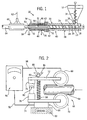
- Fig. 1 is a cross sectional view of the apparatus for the continuous extrusion of block filter elements in accordance with the present invention;
- Fig. 2 is a side elevational view of a back pressure control device for controlling the back pressure on the block formed by the extruder apparatus of Fig. 1;
- Fig. 3 is an enlarged, side elevational view of a portion of a screw for use with the extruder apparatus of Fig. 1;
- Fig. 4 is an end view of the screw of Fig. 3; and
- Fig. 5 is an enlarged, side elevational view of an alternate end portion of a screw for use with the extruder apparatus of Fig. 1.
-
- Referring to Fig. 1, the extruder apparatus of the present invention is generally designated by the
reference numeral 10. In the preferred embodiment,extruder apparatus 10 is designed to continuously extrude porous activated carbon block filter elements formed from a mixture of premixed material such as granular or powdered carbon and a polyolefin binder such as polyethylene. However, it is contemplated as being within the scope of the present invention to provide an extruder apparatus to produce other hollow, composite solid articles from a mixture of other materials. - As best seen in Fig. 1,
hopper 12 is provided which is adapted for receiving a mixture therein. The mixture is in the form of a thoroughly mixed powder comprising a thermoplastic binder material, for example, polyethylene, and a powdered or granular primary material such as, for example, activated carbon. Hopper 12 includes avertical auger 14 which feeds the mixture toward thefeed throat 16. Thefeed throat 16 ofhopper 12 communicates with theinterior 18 of generallycylindrical barrel 20. -
Barrel 20 extends along a longitudinal axis and includes aninner wall 22 which defines theinterior 18 ofbarrel 20 from anupstream input port 23 to anoutput end 42. Arotatable screw 24 is positioned within theinterior 18 ofbarrel 20 and is coaxial withbarrel 20.Screw 24 has an elongated, generallycylindrical core 26 surrounded by a conventional,helical flight 28. The root diameter (core 26) of the screw increases gradually from theinput port 23 in the downstream direction. - Referring to Figs. 3 and 4,
screw 24 includes a firstforward end 30.Forward end 30 ofscrew 24 is tapered such that the diameter ofcore 26 is sharply reduced. Thetaper 31 of theforward end 30 acts to provide a region of increased volume for the heated agglomerated material as it passes from the extruder into the die where the flowing material is further mixed and agitated.Forward end 30 also includes a recessed cavity 32 (shown in phantom) in theforward surface 34 ofscrew 24 to facilitate the interconnection of the end of amandrel 36 thereto.Helical flight 28 terminates near theforward end 30 ofscrew 24 at asurface 37 which is transverse and, preferably, perpendicular to the longitudinal axis along whichscrew 24 extends. - Referring to Fig. 5, a second embodiment of
screw 24 is shown. Common reference characters are used to facilitate understanding.Screw 24 includes the firstforward end 30.Forward end 30 ofscrew 24 is tapered such that the diameter ofcore 26 is gradually reduced. Thetapered portion 35 ofcore 26 terminates at ashoulder 39 which defines a generally flat disk shapedsurface 41. The disk shapedsurface 41 is spaced from theforward surface 34 ofscrew 24 by a generallycylindrical portion 43 ofcore 26. - As is known, the premixed material must be preheated in
barrel 20 by preheatingelement 38 in order that the premixed material remains flowable. The composite material is then further heated by aprimary heater 40 to the required processing temperature at or below the resin melting temperature. As the premixed material absorbs heat from thebarrel 20, the polyethylene binder becomes soft, partially melts, and starts to create "bridges" between the carbon granules so as to form an agglomerated mass that is forced from theoutput end 42 ofbarrel 20. - The output end 42 of
barrel 20 feeds into an input end of adie assembly 44. The dieassembly 44 includes anelongated die 46 having aninner surface 48 which defines a generallycylindrical passageway 50 therethrough. Awater cooling jacket 52 is positioned about theouter periphery 51 of die 46.Water cooling jacket 52 includes awater inlet 54 and awater outlet 56 to provide for the flow of cooling water throughwater cooling jacket 52. The cooling water is maintained at a temperature below the resin melting temperature. - As hereinafter described, agglomerated mass which enters die assembly partially solidifies therein, and forms an extruded
block 64. Extrudedblock 64 which exits theoutput end 58 of the die 46 passes through a coolingtunnel 60 positioned adjacent to die 46. Coolingtunnel 60 includes aninlet 62 which receives cool air and passes it over the extrudedblock 64 in order to completely solidify the final composite product. - Referring to Fig. 2, in order to control the pressure of material within
die 46, a backpressure control device 66 is provided. Backpressure control device 66 provides a resistance to movement of the extrudedblock 64 fromdie 46. Backpressure control device 66 includes first 68 and second 70 spaced wheels, which are held in rotational contact with the continuousextruded product 64 as it exits from coolingtunnel 60 at a rate equal to the desired rate of extrusion. In a preferred embodiment,wheels -
Wheels corresponding support plates support plate support member support members hinge 80 thereby allowingplates hinge 80 so as to vary the vertical space betweenwheels tie rod 82 also interconnectsplates Tie rod 82 includes aspring 84 whichbiases plate wing nut 86 is positioned over afirst end 88 oftie rod 82 to provide a selected and adjustable bearing load to be applied through thewheels - A
load cell 90 is interconnected betweenplate 74 and astationary surface 93 for measuring the back pressure force. Theload cell 90 provides a signal proportional to the back pressure force alongdata line 92 totension controller 94.Tension controller 94, which controls the brake tension on one or bothwheels block 64. Air brake may be controlled by the pressure inbrake line 96. - In operation, the premixed material of carbon and polyethylene binder is fed into the
hopper 12 at room temperature.Vertical auger 14, turning at a low speed, feeds the premixed material through thefeed throat 16 into the interior 18 ofbarrel 20. Asscrew 24 rotates, the premixed material moves along the interior 18 ofbarrel 20 towardforward end 30 ofbarrel 20. The increasing root diameter of thecore 26 of the screw causes the advancing mixture to be compressed and entrapped air to be squeezed from it. The premixed material is preheated bypreheater 38 and thereafter byheater 40. The premixed material absorbs heat frombarrel 20 such that the polyethylene binder becomes soft, partially melts and starts to create "bridges" between the carbon granules. An agglomerated mass is formed which is urged through theoutput end 42 ofbarrel 20 intodie assembly 44. - The tapered, reduced diameter forward end 30 of
screw 24 allows space for the flowing, premixed material to become mixed and agitated byflight 28, Fig. 3. Thesurface 37 offlight 28 acts to agitate the agglomerated mass, and to compact the agglomerated mass into thedie 44. The agitation and mixing of the material that occurs at thescrew end 30 has been found to disrupt the spiral pattern which is imparted to the composite material as it moves along the screw. This process of extrusion allows for the continuous formation of a uniform homogenous extruded product, eliminating the visual spiral marks and spiraling areas of higher and lower density. - In the alternate embodiment of
screw 24, the increased space between thecylindrical surface 43 and theinner wall 22 ofbarrel 20 allows additional space for the flowing, premixed material to become mixed and agitated. - The agglomerated mass is forced into the
passageway 50 ofdie 46 and around the outer periphery ofmandrel 36 such thatmandrel 36 shapes the inner diameter of the extrudedblock 64 to be formed. Cooling water is circulated throughwater cooling jacket 52 so as to remove excess heat from the agglomerated mass thereby forming the extrudedblock 64. The melting temperature of the resin is typically in the range of 200-500°F. and, therefore, the cooling water may be maintained at any suitable lower temperature, typically in the range of 90-140°F. Extruded block 64 comes out of die 44 with some rigidity. As such, extrudedblock 64 is passed through coolingtunnel 60 so as to further solidify the extrudedblock 64 and form the solid end product. - Extruded
block 64 then passes between first 68 and second 70 wheels of backpressure control device 66. The back pressure applied to the extrudedblock 64 controls the density ofextruded block 64. Hence, the more back pressure applied on the extrudedblock 64, the greater its density will be, and vice versa. - As previously described, back pressure in the extrusion process is controlled by the two
urethane wheels tension controller 94 for a predetermined back pressure force. The compressive force applied by first 68 and second 70 wheels is initially set by adjustingwing nut 86 onto or off of tie rod 85. The compressive force between first 68 and second 70 wheels allow the wheels to grip extrudedblock 64.Tension controller 94 controls the brake tension on thewheels brake line 96. - The amount of back pressure force on extruded
block 64 is controlled bytension controller 94 which is connected to loadcell 90 mounted betweenplate 74 andground 93.Load cell 90 provides a signal representative of the back pressure force on extrudedblock 64 and provides the information totension controller 94 alongdata line 92 which, in turn, varies the brake tension on first 68 and/or second 70 wheels to maintain a constant back pressure. - Various modes of carrying out the invention are contemplated as being in the scope of the following claims.
Claims (13)
- A method for the continuous extrusion of a porous composite block element (64) from a mixture of a resin binder and a granular base material in a screw extruder (10) of the type having a feed screw (24) rotatably mounted in the cylindrical interior of a barrel (20), and a die (44) connected to the barrel (20) to receive material from the barrel and form the extruded element, said method comprising the steps of:(1) feeding the mixture in a solid state into the barrel (20);(2) heating the mixture in the barrel (20) to melt the resin binder and cause the mixture to agglomerate;(3) providing a mixing region in the barrel (20) at the downstream end of the barrel (20) and upstream of the die (44) to cause increased agitation of the mixture; and,(4) advancing the agitated mixture directly into the die (44).
- The method as set forth in claim 1 wherein the feed screw (24) includes a central core (26) and a helical flight (28) extending radially from the core (26) and wherein the step of providing a mixing region comprises reducing the screw core (26) diameter at the downstream end thereof.
- The method as set forth in claim 2 wherein the step of reducing the core diameter comprises tapering the end of the core along approximately the last pitch length of the flight (28).
- The method as set forth in claim 2 wherein the step of reducing the core (26) diameter comprises providing a shoulder (39) defining a reduced diameter cylindrical end portion.
- An extrusion device (10) having a hollow, generally cylindrical barrel (20) extending along a longitudinal axis, the barrel (20) having an input port for the binder and base material and a discharge port;for forming a composite block of a resin binder and a granular base material, the resin binder having a predetermined processing temperature: characterised bya screw (24) having a helical flight (28) positioned coaxially within the barrel (20) between the input and discharge ports, the screw (24) rotatable about the longitudinal axis;a heater (40) positioned between the input port and the discharge port for heating the resin binder to the processing temperature;a mixing and agitating region defined by the screw (24) and the barrel (20) at the discharge port of the barrel (20);a die assembly (44) extending along the longitudinal axis adjacent to the barrel (20), the die assembly having an inlet end in communication with the discharge port of the barrel (20),the discharge end for the composite block being maintained at a temperature below the processing temperature of the base material; anda cooling device (52) being positioned about the die assembly for cooling the die (44) assembly to a predetermined temperature.
- The extrusion device (10) of claim 5 wherein the helical flight (28) of the screw projects from a generally cylindrical core (26), the core (26) having a first end adjacent the discharge port of the barrel (20) and a second end adjacent the input port of the barrel (20), and the mixing and agitating region comprises a reduced diameter portion on the first end of the core (26).
- The extrusion device (10) of claim 5 wherein the helical flight (28) terminates at the discharge port in a generally flat surface, transverse to the longitudinal axis of the barrel (20).
- The extrusion device (10) of claim 5 wherein the die assembly (44) includes an extruded block forming cavity positioned between the input end and the discharge end of the die assembly (44).
- The extrusion device (10) of claim 8 further comprising a generally cylindrical mandrel extending through the block forming cavity in the die assembly (44).
- The extrusion device (10) of claim 5 further comprising a back pressure control device (66), the back pressure control device (66) including first (68) and second (70) opposed wheels mounted to engage the extruded block (64) emerging from the discharge end of the die, each wheel (68, 70) rotatable about a distinct axis transverse to the longitudinal axis.
- The extrusion device (10) of claim 10 further comprising a means for varying compressive force between the wheels (68, 70).
- The extrusion device (10) of claim 10 further comprising a variable resistance brake for limiting rotation of each wheel.
- The extrusion device (10) of claim 12 further comprising a means (94) for monitoring the braking resistance and adjusting the braking resistance to a predetermined value.
Applications Claiming Priority (3)
| Application Number | Priority Date | Filing Date | Title |
|---|---|---|---|
| US08/711,090 US5976432A (en) | 1996-09-09 | 1996-09-09 | Method and apparatus for the continuous extrusion of block elements |
| US711090 | 1996-09-09 | ||
| PCT/US1997/015379 WO1998009709A1 (en) | 1996-09-09 | 1997-08-29 | Method and apparatus for the continuous extrusion of block elements |
Publications (2)
| Publication Number | Publication Date |
|---|---|
| EP0925102A1 EP0925102A1 (en) | 1999-06-30 |
| EP0925102B1 true EP0925102B1 (en) | 2000-05-17 |
Family
ID=24856735
Family Applications (1)
| Application Number | Title | Priority Date | Filing Date |
|---|---|---|---|
| EP97940735A Expired - Lifetime EP0925102B1 (en) | 1996-09-09 | 1997-08-29 | Method and apparatus for the continuous extrusion of block elements |
Country Status (8)
| Country | Link |
|---|---|
| US (1) | US5976432A (en) |
| EP (1) | EP0925102B1 (en) |
| JP (1) | JP3758682B2 (en) |
| KR (1) | KR100481656B1 (en) |
| CN (1) | CN1079687C (en) |
| DE (1) | DE69702071T2 (en) |
| ES (1) | ES2149004T3 (en) |
| WO (1) | WO1998009709A1 (en) |
Families Citing this family (43)
| Publication number | Priority date | Publication date | Assignee | Title |
|---|---|---|---|---|
| RU2171744C1 (en) * | 2000-09-28 | 2001-08-10 | Общество с ограниченной ответственностью "Аквафор" | Method and device for continuous extrusion of filter elements |
| FR2832667B1 (en) * | 2001-11-27 | 2006-10-13 | Claude Ailleau | PROCESS AND INSTALLATION FOR MANUFACTURING POROUS PARTS THROUGH AGGLOMERATION OF PELLETS IN THERMOPLASTIC MATERIAL |
| US6682667B1 (en) | 2002-02-05 | 2004-01-27 | Calgon Carbon Corporation | Method for producing self-supporting activated carbon structures |
| KR100503440B1 (en) * | 2002-06-18 | 2005-07-26 | 에스케이케미칼주식회사 | Method and apparatus for profile extruding polyester resin |
| US7112272B2 (en) | 2002-08-12 | 2006-09-26 | 3M Innovative Properties Company | Liquid and gas porous plastic filter and methods of use |
| US7169304B2 (en) * | 2002-08-12 | 2007-01-30 | 3M Innovative Properties Company | Porous polymer water filter and methods of use in refrigeration |
| US7112280B2 (en) | 2002-08-12 | 2006-09-26 | 3M Innovative Properties Company | Gas porous polymer filter and methods of use |
| US7252757B2 (en) | 2002-09-09 | 2007-08-07 | Clarity Filters Llc | Faucet-mounted water filtration device including gate position sensor |
| US7258781B2 (en) | 2002-09-09 | 2007-08-21 | Clarity Filters Llc | Single-use long-life faucet-mounted water filtration devices |
| GB2399532B (en) * | 2003-03-19 | 2007-10-24 | Econoplas Ltd | Method of manufacturing drainage/irrigation elements from recycled plastics |
| USD498512S1 (en) | 2003-07-03 | 2004-11-16 | Clear Flow Corporation | Water filter |
| US7022274B2 (en) * | 2003-11-25 | 2006-04-04 | Graver Technologies, Llc. | Gas sintered carbon block and method |
| US7704907B2 (en) * | 2005-08-25 | 2010-04-27 | Ceramext, Llc | Synthesized hybrid rock composition, method, and article formed by the method |
| USD541372S1 (en) | 2005-11-01 | 2007-04-24 | Clarity Filters Llc | Water filter |
| KR100674078B1 (en) * | 2006-01-09 | 2007-01-24 | 김민형 | Carbon filter manufacturing apparatus and method |
| KR101430206B1 (en) * | 2007-11-09 | 2014-08-14 | 주식회사 칸세라 | Apparatus for preventing extruded product from bending |
| EP2242725B1 (en) * | 2007-12-21 | 2016-04-06 | 3M Innovative Properties Company | Liquid filtration systems |
| DE102009032287A1 (en) | 2009-01-20 | 2010-08-05 | Evonik Degussa Gmbh | Extrusion plant with dynamic pressure regulating braking device |
| EP2255680A1 (en) * | 2009-05-28 | 2010-12-01 | SPX APV Danmark A/S | Food product heat treatment apparatus and method for heat treating food products |
| US20110168876A1 (en) * | 2010-01-14 | 2011-07-14 | Hsiung Hsiao | Optical module and system for liquid sample |
| CN103167940B (en) * | 2010-11-04 | 2016-09-21 | 3M创新有限公司 | The method forming filter element |
| CN102280212B (en) * | 2011-05-23 | 2013-04-10 | 江苏港通电缆有限公司 | Water-cooled stranding device used in cable-conductive-core strand production |
| JP5951798B2 (en) * | 2012-01-05 | 2016-07-13 | アウディ アクチェンゲゼルシャフトAudi Ag | Method for manufacturing a plurality of fuel cell separator plate assemblies |
| KR101587617B1 (en) * | 2013-10-24 | 2016-01-21 | 주식회사 마이크로필터 | Dubble Extrudesion Molding Apparatus for Carbon Block, Molding Method Using the Same and Carbon Block Using the Same |
| CN103816710B (en) * | 2014-03-28 | 2016-04-06 | 陆向东 | Antimicrobial filtering pipe |
| CN105599113B (en) * | 2015-12-29 | 2018-02-16 | 浙江轩鸣新材料有限公司 | It is incubated pipe forming machine |
| CN105690851A (en) * | 2016-01-05 | 2016-06-22 | 无锡市宏腾塑胶厂 | Air-cooled carbon rod extruder |
| CN106215527B (en) * | 2016-08-22 | 2017-11-24 | 广州康瑞环保科技有限公司 | Filter medium, its sintering method and the sintering equipment for implementing this method |
| CN106345389B (en) * | 2016-10-27 | 2019-03-22 | 广东华特气体股份有限公司 | A kind of reactor with refrigerating function |
| CN107090661A (en) * | 2017-05-22 | 2017-08-25 | 海安国洋机械科技有限公司 | The crush cutting of Self-spraying metallic fiber spreads felt machine |
| CN107087807B (en) * | 2017-05-23 | 2019-05-03 | 扬州大学 | A feeding device for extrusion puffing machine |
| CN108943643A (en) * | 2018-08-06 | 2018-12-07 | 南京欧纳壹有机光电有限公司 | A kind of raw material premix device of modified plastics double helix extrusion molding system |
| CN109927262A (en) * | 2019-04-11 | 2019-06-25 | 东莞市贝诺保温材料有限公司 | A kind of foaming tube process equipment and preparation method thereof and its method |
| CN111391266A (en) * | 2020-04-27 | 2020-07-10 | 深圳市百乐趣科技有限公司 | Pok plastic bar forming and extruding equipment |
| CN116234675A (en) * | 2020-09-21 | 2023-06-06 | 阿科玛股份有限公司 | Method and extruder for preparing high-quality immobilized active medium blocks |
| JP2023543436A (en) * | 2020-09-21 | 2023-10-16 | アーケマ・インコーポレイテッド | Method and extruder for preparing high quality blocks of immobilized active media |
| CN114248489B (en) * | 2020-09-21 | 2025-12-12 | 阿科玛股份有限公司 | Method and extruder for preparing high-quality immobilized active media blocks |
| IT202000022423A1 (en) * | 2020-09-23 | 2022-03-23 | Sacmi | CONTINUOUS CYCLE FORMING SYSTEM AND METHOD OF SINGLE OBJECTS IN PLASTIC MATERIAL |
| EP4263169A4 (en) * | 2020-12-18 | 2024-11-27 | Arkema, Inc. | Method and extruder for preparing a high quality block of immobilized active media |
| CN114804909B (en) * | 2022-05-10 | 2023-07-28 | 江西省东茂环保材料有限公司 | A kind of lightweight porous bio-ceramsite |
| CN115722667B (en) * | 2022-11-30 | 2023-06-16 | 华中科技大学 | Horizontal continuous material-adding screw extrusion equipment for sectional materials and preparation method |
| CN116118142B (en) * | 2022-12-14 | 2023-09-12 | 江苏君华特种工程塑料制品有限公司 | Plastic section bar cold-pushing forming damping machine |
| KR102904643B1 (en) | 2022-12-29 | 2025-12-26 | 주식회사 세명하이트 | Manufacturing Machine and Method For Cylindrical Activated Carbon Filter |
Family Cites Families (22)
| Publication number | Priority date | Publication date | Assignee | Title |
|---|---|---|---|---|
| US3164375A (en) * | 1955-10-14 | 1965-01-05 | Frenkel Ag C D | Apparatus for intensive mixing |
| US3268633A (en) * | 1965-09-21 | 1966-08-23 | Kaiser Ind Corp | Method of continuously forming carbon articles |
| NL6701289A (en) * | 1967-01-27 | 1967-04-25 | ||
| US3685804A (en) * | 1970-10-26 | 1972-08-22 | Sterling Extruder Corp | Mixing apparatus and method |
| US3795386A (en) * | 1971-08-16 | 1974-03-05 | Monsanto Co | Shaft seal for low and high pressures |
| JPS5221193B2 (en) * | 1971-12-17 | 1977-06-08 | ||
| US3879158A (en) * | 1973-01-09 | 1975-04-22 | Enrique Schele | Apparatus for extruding thermoplastic annular shapes |
| US3989433A (en) * | 1974-11-18 | 1976-11-02 | General Electric Company | Apparatus for controlling resistance to extrusion of a rod-like body through a die |
| US3954366A (en) * | 1975-01-06 | 1976-05-04 | Fields Reuben T | Two-stage single screw extrusion apparatus |
| CA1074780A (en) * | 1976-07-14 | 1980-04-01 | Frenkel C-D Aktiengesellschaft | Opposite handed variable groove threaded screw and barrel transfer mixer |
| DE3207856A1 (en) * | 1982-03-05 | 1983-09-15 | Basf Ag, 6700 Ludwigshafen | ROLLING PRESS FOR THE PRODUCTION OF GRANULES OR FORMS |
| US4557885A (en) * | 1984-06-12 | 1985-12-10 | Rca Corporation | Method of producing capacitive electronic discs |
| JPS6225030A (en) * | 1985-07-25 | 1987-02-03 | Ube Ind Ltd | Continuously molding method for polyimide powder |
| SE461139B (en) * | 1988-10-19 | 1990-01-15 | Curt Andersson | MADE TO MANUFACTURE PIPES AND DEVICE BEFORE ITS PREPARATION |
| US5019311A (en) * | 1989-02-23 | 1991-05-28 | Koslow Technologies Corporation | Process for the production of materials characterized by a continuous web matrix or force point bonding |
| JP2500277B2 (en) * | 1990-11-27 | 1996-05-29 | 三井東圧化学株式会社 | Extrusion molding method and apparatus for phenol resin pipe |
| TW254883B (en) * | 1991-04-03 | 1995-08-21 | Mitsui Petroleum Chemicals Ind | |
| US5189092A (en) * | 1991-04-08 | 1993-02-23 | Koslow Technologies Corporation | Method and apparatus for the continuous extrusion of solid articles |
| US5249948A (en) * | 1991-04-08 | 1993-10-05 | Koslow Technologies Corporation | Apparatus for the continuous extrusion of solid articles |
| JPH09511457A (en) * | 1994-01-19 | 1997-11-18 | ザ ダウ ケミカル カンパニー | Single screw extrusion method and device |
| US5597891A (en) * | 1995-08-01 | 1997-01-28 | Eastman Chemical Company | Process for producing polyester articles having low acetaldehyde content |
| US5694833A (en) * | 1996-07-18 | 1997-12-09 | Wenger Manufacturing, Inc. | Short length tapered extrusion cooking device |
-
1996
- 1996-09-09 US US08/711,090 patent/US5976432A/en not_active Expired - Lifetime
-
1997
- 1997-08-29 DE DE69702071T patent/DE69702071T2/en not_active Expired - Lifetime
- 1997-08-29 WO PCT/US1997/015379 patent/WO1998009709A1/en not_active Ceased
- 1997-08-29 JP JP51279298A patent/JP3758682B2/en not_active Expired - Fee Related
- 1997-08-29 EP EP97940735A patent/EP0925102B1/en not_active Expired - Lifetime
- 1997-08-29 CN CN97198990A patent/CN1079687C/en not_active Expired - Fee Related
- 1997-08-29 ES ES97940735T patent/ES2149004T3/en not_active Expired - Lifetime
- 1997-08-29 KR KR10-1999-7001986A patent/KR100481656B1/en not_active Expired - Fee Related
Also Published As
| Publication number | Publication date |
|---|---|
| KR100481656B1 (en) | 2005-04-11 |
| CN1079687C (en) | 2002-02-27 |
| JP2001501141A (en) | 2001-01-30 |
| EP0925102A1 (en) | 1999-06-30 |
| HK1022855A1 (en) | 2000-08-25 |
| US5976432A (en) | 1999-11-02 |
| WO1998009709A1 (en) | 1998-03-12 |
| DE69702071T2 (en) | 2000-12-21 |
| JP3758682B2 (en) | 2006-03-22 |
| DE69702071D1 (en) | 2000-06-21 |
| CN1233971A (en) | 1999-11-03 |
| KR20000068527A (en) | 2000-11-25 |
| ES2149004T3 (en) | 2000-10-16 |
Similar Documents
| Publication | Publication Date | Title |
|---|---|---|
| US5976432A (en) | Method and apparatus for the continuous extrusion of block elements | |
| US5653534A (en) | Screw apparatus and method for supplying reinforcing fiber-containing molten resin using the apparatus | |
| USRE23880E (en) | Extruder | |
| US20020062740A1 (en) | Method and apparatus for continuous extrusion of filter elements | |
| US4639143A (en) | Extrusion screw | |
| US6776596B2 (en) | Apparatus for the manufacture of fiber-reinforced plastic compositions | |
| JP2001501549A (en) | Manufacturing method and equipment for extruded plastic products, and plastic products | |
| US3782870A (en) | Apparatus for extruding a partially foamed thermoplastic product | |
| CZ280786B6 (en) | Extruding machine | |
| US4139309A (en) | Apparatus and method | |
| KR20100087014A (en) | Method for extruding plastic material and extruder | |
| JPH10138306A (en) | Screw of plasticizing apparatus and use thereof | |
| US6672753B1 (en) | Apparatus for plasticating thermoplastics | |
| EP2204272B1 (en) | Plasticating screw with two helical threads of varying pitches and a plasticating apparatus comprising this | |
| EP0831986B1 (en) | Feed device and method for extruders | |
| US5931578A (en) | Extruder and extrusion screw therefor | |
| US4842788A (en) | Process of an apparatus for extruding a meltable composition | |
| JPS59194821A (en) | Composite resin molding machine | |
| US20070104022A1 (en) | Extruder screw with mixing section | |
| US6062717A (en) | Chopper mixing screw | |
| HK1022855B (en) | Method and apparatus for the continuous extrusion of block elements | |
| US6699416B2 (en) | Impact modifier material and method and apparatus for the production thereof | |
| EP3095574A1 (en) | Method and device for producing a foamed granulate, and foamed granulate so produced | |
| JPS5892545A (en) | Extruder for molding thermoplastic resin | |
| JPH10109349A (en) | Screw extruder |
Legal Events
| Date | Code | Title | Description |
|---|---|---|---|
| PUAI | Public reference made under article 153(3) epc to a published international application that has entered the european phase |
Free format text: ORIGINAL CODE: 0009012 |
|
| 17P | Request for examination filed |
Effective date: 19990317 |
|
| AK | Designated contracting states |
Kind code of ref document: A1 Designated state(s): BE DE ES FR GB IT NL |
|
| GRAG | Despatch of communication of intention to grant |
Free format text: ORIGINAL CODE: EPIDOS AGRA |
|
| 17Q | First examination report despatched |
Effective date: 19991001 |
|
| GRAG | Despatch of communication of intention to grant |
Free format text: ORIGINAL CODE: EPIDOS AGRA |
|
| GRAH | Despatch of communication of intention to grant a patent |
Free format text: ORIGINAL CODE: EPIDOS IGRA |
|
| GRAH | Despatch of communication of intention to grant a patent |
Free format text: ORIGINAL CODE: EPIDOS IGRA |
|
| GRAA | (expected) grant |
Free format text: ORIGINAL CODE: 0009210 |
|
| AK | Designated contracting states |
Kind code of ref document: B1 Designated state(s): BE DE ES FR GB IT NL |
|
| REF | Corresponds to: |
Ref document number: 69702071 Country of ref document: DE Date of ref document: 20000621 |
|
| ITF | It: translation for a ep patent filed | ||
| ET | Fr: translation filed | ||
| REG | Reference to a national code |
Ref country code: ES Ref legal event code: FG2A Ref document number: 2149004 Country of ref document: ES Kind code of ref document: T3 |
|
| PLBE | No opposition filed within time limit |
Free format text: ORIGINAL CODE: 0009261 |
|
| STAA | Information on the status of an ep patent application or granted ep patent |
Free format text: STATUS: NO OPPOSITION FILED WITHIN TIME LIMIT |
|
| 26N | No opposition filed | ||
| REG | Reference to a national code |
Ref country code: GB Ref legal event code: IF02 |
|
| PGFP | Annual fee paid to national office [announced via postgrant information from national office to epo] |
Ref country code: DE Payment date: 20130821 Year of fee payment: 17 |
|
| PGFP | Annual fee paid to national office [announced via postgrant information from national office to epo] |
Ref country code: NL Payment date: 20140820 Year of fee payment: 18 |
|
| PGFP | Annual fee paid to national office [announced via postgrant information from national office to epo] |
Ref country code: FR Payment date: 20140821 Year of fee payment: 18 Ref country code: ES Payment date: 20140821 Year of fee payment: 18 Ref country code: GB Payment date: 20140820 Year of fee payment: 18 |
|
| PGFP | Annual fee paid to national office [announced via postgrant information from national office to epo] |
Ref country code: BE Payment date: 20140820 Year of fee payment: 18 |
|
| REG | Reference to a national code |
Ref country code: DE Ref legal event code: R119 Ref document number: 69702071 Country of ref document: DE |
|
| PGFP | Annual fee paid to national office [announced via postgrant information from national office to epo] |
Ref country code: IT Payment date: 20140826 Year of fee payment: 19 |
|
| REG | Reference to a national code |
Ref country code: DE Ref legal event code: R119 Ref document number: 69702071 Country of ref document: DE Effective date: 20150303 |
|
| PG25 | Lapsed in a contracting state [announced via postgrant information from national office to epo] |
Ref country code: DE Free format text: LAPSE BECAUSE OF NON-PAYMENT OF DUE FEES Effective date: 20150303 |
|
| GBPC | Gb: european patent ceased through non-payment of renewal fee |
Effective date: 20150829 |
|
| REG | Reference to a national code |
Ref country code: NL Ref legal event code: MM Effective date: 20150901 |
|
| REG | Reference to a national code |
Ref country code: FR Ref legal event code: ST Effective date: 20160429 |
|
| PG25 | Lapsed in a contracting state [announced via postgrant information from national office to epo] |
Ref country code: NL Free format text: LAPSE BECAUSE OF NON-PAYMENT OF DUE FEES Effective date: 20150901 |
|
| PG25 | Lapsed in a contracting state [announced via postgrant information from national office to epo] |
Ref country code: GB Free format text: LAPSE BECAUSE OF NON-PAYMENT OF DUE FEES Effective date: 20150829 |
|
| PG25 | Lapsed in a contracting state [announced via postgrant information from national office to epo] |
Ref country code: FR Free format text: LAPSE BECAUSE OF NON-PAYMENT OF DUE FEES Effective date: 20150831 |
|
| REG | Reference to a national code |
Ref country code: ES Ref legal event code: FD2A Effective date: 20160926 |
|
| PG25 | Lapsed in a contracting state [announced via postgrant information from national office to epo] |
Ref country code: ES Free format text: LAPSE BECAUSE OF NON-PAYMENT OF DUE FEES Effective date: 20150830 |
|
| PG25 | Lapsed in a contracting state [announced via postgrant information from national office to epo] |
Ref country code: BE Free format text: LAPSE BECAUSE OF NON-PAYMENT OF DUE FEES Effective date: 20150831 |
|
| PG25 | Lapsed in a contracting state [announced via postgrant information from national office to epo] |
Ref country code: IT Free format text: LAPSE BECAUSE OF NON-PAYMENT OF DUE FEES Effective date: 20160829 |