EP0924847A2 - Method and circuit arrangement for commutation of a multiple winding electric motor - Google Patents
Method and circuit arrangement for commutation of a multiple winding electric motor Download PDFInfo
- Publication number
- EP0924847A2 EP0924847A2 EP98123071A EP98123071A EP0924847A2 EP 0924847 A2 EP0924847 A2 EP 0924847A2 EP 98123071 A EP98123071 A EP 98123071A EP 98123071 A EP98123071 A EP 98123071A EP 0924847 A2 EP0924847 A2 EP 0924847A2
- Authority
- EP
- European Patent Office
- Prior art keywords
- voltage
- circuit arrangement
- motor
- ramp voltage
- commutation
- Prior art date
- Legal status (The legal status is an assumption and is not a legal conclusion. Google has not performed a legal analysis and makes no representation as to the accuracy of the status listed.)
- Granted
Links
- 238000004804 winding Methods 0.000 title claims abstract description 29
- 238000000034 method Methods 0.000 title claims abstract description 9
- 238000011144 upstream manufacturing Methods 0.000 claims abstract description 5
- 230000000737 periodic effect Effects 0.000 claims description 8
- 125000004122 cyclic group Chemical group 0.000 claims description 3
- 230000001629 suppression Effects 0.000 abstract description 4
- 230000001360 synchronised effect Effects 0.000 abstract description 2
- 238000005516 engineering process Methods 0.000 abstract 1
- 239000003990 capacitor Substances 0.000 description 4
- 230000033228 biological regulation Effects 0.000 description 3
- 230000001133 acceleration Effects 0.000 description 2
- 238000004519 manufacturing process Methods 0.000 description 2
- 230000001276 controlling effect Effects 0.000 description 1
- 238000013016 damping Methods 0.000 description 1
- 230000001419 dependent effect Effects 0.000 description 1
- 238000011161 development Methods 0.000 description 1
- 230000018109 developmental process Effects 0.000 description 1
- 230000010363 phase shift Effects 0.000 description 1
- 230000001105 regulatory effect Effects 0.000 description 1
- 230000000630 rising effect Effects 0.000 description 1
- 230000007704 transition Effects 0.000 description 1
Images


Classifications
-
- H—ELECTRICITY
- H02—GENERATION; CONVERSION OR DISTRIBUTION OF ELECTRIC POWER
- H02P—CONTROL OR REGULATION OF ELECTRIC MOTORS, ELECTRIC GENERATORS OR DYNAMO-ELECTRIC CONVERTERS; CONTROLLING TRANSFORMERS, REACTORS OR CHOKE COILS
- H02P6/00—Arrangements for controlling synchronous motors or other dynamo-electric motors using electronic commutation dependent on the rotor position; Electronic commutators therefor
- H02P6/14—Electronic commutators
-
- H—ELECTRICITY
- H02—GENERATION; CONVERSION OR DISTRIBUTION OF ELECTRIC POWER
- H02P—CONTROL OR REGULATION OF ELECTRIC MOTORS, ELECTRIC GENERATORS OR DYNAMO-ELECTRIC CONVERTERS; CONTROLLING TRANSFORMERS, REACTORS OR CHOKE COILS
- H02P2209/00—Indexing scheme relating to controlling arrangements characterised by the waveform of the supplied voltage or current
- H02P2209/07—Trapezoidal waveform
Definitions
- the present invention is based on a method and a circuit arrangement having a controller for commutation of a multiple winding electric motor.
- a circuit arrangement of this type has been disclosed, for example, in EP 0 574 435 B1.
- a motor having three winding sections is driven by a pulse generator via an output amplifier. Regulation is achieved via a sensor which detects the revolutions of the motor.
- the pulse generator in this arrangement produces square-wave signals, which cyclically pass through the states +1, 0, -1, 0, +1 etc. Since interference pulses occur at certain transitions between these states, suitable means have to be provided for suppression.
- EP 0 259 764 B1 discloses a further circuit arrangement for commutation of an electric motor, which is based on digital circuits.
- commutation pulses from a sensor arranged on the motor are used in a counter and an associated logic circuit to produce three phase-shifted signal voltages for driving the three winding sections.
- These voltages are used in a downstream decoder to generate six phase-shifted signal voltages, from which currents with a square-wave amplitude are produced, via invertors, OR circuits and six switches, and are used to drive the motor.
- the circuit complexity is relatively high in this case, particularly since the six switches have to switch high currents.
- the object of the present invention is to specify a circuit arrangement for commutation of a multiple winding electric motor, and a method relating to this, which has a low circuit complexity level with good suppression of interference pulses.
- the circuit arrangement for commutation in the present invention contains switching means, using which, controlled by a controller, a periodic, trapezoidal waveform control signal for driving a respective winding section is formed from a supply voltage or an equivalent DC voltage, a reference potential and a triangular waveform ramp voltage.
- This control signal contains no switching pulses with steep edges, so that the inductances in the motor cannot produce any excessive interference voltages.
- the control signal is formed in particular upstream of the output amplifier of a respective winding section, so that no high currents are switched by the switching means.
- each winding section is operated by the output amplifier with low impedance at all times, resulting in good additional damping.
- a signal derived from the supply voltage or a signal generated in some other way may also be used instead of a supply voltage.
- the periodic, trapezoidal waveform control signal is produced by cyclic switching from the two voltages and the reference potential, the switching time either being dictated by the controller or being derived from signal pulses from a sensor S arranged on the motor. For example, 24 times are required, at equal time intervals per motor revolution, in order to produce the ramp voltage, for example for a motor having three winding sections. These times govern the times from which the three trapezoidal waveform control signals are formed in order to drive these winding sections, one ramp voltage being sufficient for all three winding sections.
- the triangular waveform ramp voltage may be produced, for example, by means of two current or voltage sources of opposite polarity, between which switching takes place periodically, and whose output voltages or currents, respectively, periodically charge and discharge a capacitor.
- other triangular waveform generators may be used, so that, for example, the ramp voltage can be produced digitally by the controller, by generating a staircase waveform voltage. Since the motor is preferably controlled by a specified control signal amplitude and not by variation of the pulse width (PWM), it is at the same time necessary to ensure that the maximum voltage of the ramp voltage matches the value of the supply voltage.
- PWM pulse width
- the motor 10 in Fig. 1a contains three winding sections 1, 2, 3, which are driven by output amplifiers 11, 12, 13. These winding sections 1, 2, 3 are driven by periodic, trapezoidal waveform control signals c, d, e, as is illustrated in Fig. 2. These control signals c, d, e are formed from a supply voltage U0 (Fig. 1a), a reference potential, in this exemplary embodiment earth, and a triangular waveform ramp voltage Ur. Alternatively, any desired voltage other than zero may be used as the reference potential, for example -Ur.
- a controller P controls the generation of these control signals c, d, e via the switches 4, 5, 6, on which the above voltages U0 and Ur and earth are respectively present, switching them onwards periodically.
- the trapezoidal waveform control signal is in this case formed successively from a positive ramp, the positive operating voltage Ur, a negative ramp and earth.
- the triangular waveform ramp voltage Ur in this case correspondingly has identical voltage levels at the switching times with respect to the operating voltage U0 and earth, so that no discontinuities occur.
- the motor 10 is started by the controller P predetermining a low frequency of revolution by means of the switches 4, 5, 6, and increasing this frequency until normal operation is reached at a specific nominal value.
- the frequency of the ramp voltage can in this case be matched to the low starting frequency during acceleration, in order to avoid abrupt voltage changes during switching.
- the circuit arrangement for commutation according to Fig. 1a can alternatively be equipped with a sensor which is arranged on the motor and predetermines commutation times which can then be used both in normal operation and during motor starting.
- the triangular waveform ramp voltage Ur is produced in this exemplary embodiment using two current sources 8, 9 of different polarity, and a switch 7.
- the switch 7 is switched periodically between the outputs of the current sources 8, 9 by means of the controller P, so that a triangular waveform ramp voltage Ur is produced using a capacitor C1, which is appropriately charged and discharged.
- two voltage sources with a resistor in series can also be used instead of the current sources 8, 9 for charging the capacitor C1, or some other triangular waveform generator can be used to produce the ramp voltage Ur.
- the ramp voltage Ur can also be produced, in particular, digitally by means of the controller P, for example by using a digital/analogue converter (DAC) to produce staircase waveform voltages.
- DAC digital/analogue converter
- the operating voltage U0 is a constant voltage and, in this exemplary embodiment, is also smoothed by a capacitor C2. Since the switches 4, 5, 6 are arranged upstream of the output amplifiers 11, 12, 13, they switch only low power levels, so that low-power transistors, in particular, can be used as the switching elements. In consequence, the three switches 4, 5, 6 can advantageously also be integrated in an IC, together with the ramp generator 7, 8, 9 and the controller P. Separate power transistors may be used as the output amplifiers 11, 12, 13. Since the winding sections 1, 2, 3 are driven directly by the output amplifiers 11, 12, 13 with low impedance, interference voltages produced in the motor 10 are effectively suppressed.
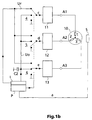
- Fig. 1b illustrates a commutation circuit which regulates the speed of the motor 10 via a sensor S.
- the commutation circuit is constructed analogously to that in Fig. 1a, and the same items have the same reference symbols.
- periodic, trapezoidal waveform control signals c, d, e for driving a respective winding section 1, 2, 3 are likewise formed from a supply voltage U0, a triangular waveform ramp voltage Ur and a reference potential, in this exemplary embodiment earth.
- the sensor S supplies a specific number of pulses a per motor revolution, these pulses being at equal time intervals, as illustrated in Fig. 2.
- These pulses are a measure of the position and speed of motor revolution and are used by the controller P to stabilize the motor speed or for acceleration and braking.
- the motor is advantageously controlled by controlling the amplitude, that is to say by variation of the supply voltage U0.
- This is generated by the controller P via an interface I which, for example, contains a digital/analogue converter (DAC).
- DAC digital/analogue converter
- the ramp voltage Ur is likewise produced digitally, and its frequency and amplitude can be matched by the controller P to the supply voltage U0, via the interface I, so that the switches 4, 5, 6 respectively form trapezoidal waveform control signals c, d, e that are as ideal as possible.
- the sensor S supplies 24 pulsed sensor signals a per motor revolution, corresponding to 360°. As described above, these pulses are used to produce the triangular waveform ramp voltage Ur, which has a period of 2 sensor pulses.
- the switches 4, 5, 6 in Fig. 1b are used to produce trapezoidal waveform control signals c, d, e from the operating voltage U0, the reference potential of earth and the ramp voltage Ur, these control signals c, d, e having a period of, for example, 6 sensor pulses, and each being phase-shifted by 2 sensor signals from one another.
- the duration of the maximum and minimum amplitude of each trapezoidal waveform control signal c, d, e respectively corresponds to the time interval between two marking pulses (t2 to t4 or t5 to t7 for the voltage c).
- the motor can be regulated by amplitude variation, as explained with reference to Fig. 1b.
- it is possible to vary the width of the maximum thus resulting in a pulse-width-modulated control signal.
- the operating voltage U0 and the maximum amplitude of the ramp voltage Ur can be kept constant, so that the motor 10 is controlled just by pulse-width modulation (PWM). Since the times of the rising edges are unchanged, this does not change the frequency, but only the pulse width.
- PWM pulse-width modulation
- the period of the trapezoidal waveform control signals c, d, e is in each case 6 pulses, and the respective phase shift is 2 pulses.
- the switches 4, 5, 6 are switched onwards alternately with a period of one or two sensor pulses, and the switch 7 is switched onwards with each sensor pulse.
- 12 sensor pulses per motor revolution may be used, for example, for commutation, the switching signals for the switch 7 being produced in the controller P in this case.
- circuit arrangements in Figures 1a and 1b each show a circuit arrangement for a motor having three winding sections, which represent a preferred exemplary embodiment. Other refinements of the invention can likewise be applied to a two winding motor or to motors with more than three winding sections.
- the circuits which are illustrated as blocks in Figures 1a and 1b are used only to assist understanding of the invention. They may also be formed and illustrated in other ways, as well as being integrated in different manners. The elements contained in the blocks may also be discrete.
Abstract
Description
- The present invention is based on a method and a circuit arrangement having a controller for commutation of a multiple winding electric motor.
- A circuit arrangement of this type has been disclosed, for example, in EP 0 574 435 B1. In this case, a motor having three winding sections is driven by a pulse generator via an output amplifier. Regulation is achieved via a sensor which detects the revolutions of the motor. The pulse generator in this arrangement produces square-wave signals, which cyclically pass through the states +1, 0, -1, 0, +1 etc. Since interference pulses occur at certain transitions between these states, suitable means have to be provided for suppression.
- EP 0 259 764 B1 discloses a further circuit arrangement for commutation of an electric motor, which is based on digital circuits. In this case, commutation pulses from a sensor arranged on the motor are used in a counter and an associated logic circuit to produce three phase-shifted signal voltages for driving the three winding sections. These voltages are used in a downstream decoder to generate six phase-shifted signal voltages, from which currents with a square-wave amplitude are produced, via invertors, OR circuits and six switches, and are used to drive the motor. The circuit complexity is relatively high in this case, particularly since the six switches have to switch high currents.
- The object of the present invention is to specify a circuit arrangement for commutation of a multiple winding electric motor, and a method relating to this, which has a low circuit complexity level with good suppression of interference pulses.
- This object is achieved by the method according to
Claim 1 and by the circuit arrangement according toClaim 5. Advantageous developments of the invention are specified in the dependent claims. - The circuit arrangement for commutation in the present invention contains switching means, using which, controlled by a controller, a periodic, trapezoidal waveform control signal for driving a respective winding section is formed from a supply voltage or an equivalent DC voltage, a reference potential and a triangular waveform ramp voltage. This control signal contains no switching pulses with steep edges, so that the inductances in the motor cannot produce any excessive interference voltages. The control signal is formed in particular upstream of the output amplifier of a respective winding section, so that no high currents are switched by the switching means. Furthermore, each winding section is operated by the output amplifier with low impedance at all times, resulting in good additional damping. A signal derived from the supply voltage or a signal generated in some other way may also be used instead of a supply voltage.
- The periodic, trapezoidal waveform control signal is produced by cyclic switching from the two voltages and the reference potential, the switching time either being dictated by the controller or being derived from signal pulses from a sensor S arranged on the motor. For example, 24 times are required, at equal time intervals per motor revolution, in order to produce the ramp voltage, for example for a motor having three winding sections. These times govern the times from which the three trapezoidal waveform control signals are formed in order to drive these winding sections, one ramp voltage being sufficient for all three winding sections.
- The triangular waveform ramp voltage may be produced, for example, by means of two current or voltage sources of opposite polarity, between which switching takes place periodically, and whose output voltages or currents, respectively, periodically charge and discharge a capacitor. Alternatively, other triangular waveform generators may be used, so that, for example, the ramp voltage can be produced digitally by the controller, by generating a staircase waveform voltage. Since the motor is preferably controlled by a specified control signal amplitude and not by variation of the pulse width (PWM), it is at the same time necessary to ensure that the maximum voltage of the ramp voltage matches the value of the supply voltage.
- The production of the supply voltage and of the ramp voltage and the switching means can advantageously be combined together with the controller required for driving and regulation in an integrated circuit, which now requires only a few external components. Applications of the invention include, in particular, use in synchronous motors for consumer electronics, for example those used in video recorders, or for computer equipment.
- The invention is explained in more detail in the following text, by way of example, using schematic drawings, in which:
- Fig. 1a
- shows a motor having three winding sections and a circuit arrangement for commutation;
- Fig. 1b
- shows the motor and the circuit arrangement from Fig. 1a with a sensor for regulation, and
- Fig. 2
- shows sensor signals from a sensor arranged on the motor, and signals derived from it.
- The
motor 10 in Fig. 1a contains threewinding sections output amplifiers winding sections switches - The
motor 10 is started by the controller P predetermining a low frequency of revolution by means of theswitches - The triangular waveform ramp voltage Ur is produced in this exemplary embodiment using two
current sources switch 7. Theswitch 7 is switched periodically between the outputs of thecurrent sources current sources - The operating voltage U0 is a constant voltage and, in this exemplary embodiment, is also smoothed by a capacitor C2. Since the
switches output amplifiers switches ramp generator output amplifiers winding sections output amplifiers motor 10 are effectively suppressed. - Fig. 1b illustrates a commutation circuit which regulates the speed of the
motor 10 via a sensor S. The commutation circuit is constructed analogously to that in Fig. 1a, and the same items have the same reference symbols. Once again, periodic, trapezoidal waveform control signals c, d, e for driving arespective winding section switches - The production of the periodic, trapezoidal waveform control signals c, d, e in the arrangement in Fig. 1b will be explained in more detail with reference to Fig. 2. In this exemplary embodiment, the sensor S supplies 24 pulsed sensor signals a per motor revolution, corresponding to 360°. As described above, these pulses are used to produce the triangular waveform ramp voltage Ur, which has a period of 2 sensor pulses. The
switches - In this exemplary embodiment, the duration of the maximum and minimum amplitude of each trapezoidal waveform control signal c, d, e respectively corresponds to the time interval between two marking pulses (t2 to t4 or t5 to t7 for the voltage c). The motor can be regulated by amplitude variation, as explained with reference to Fig. 1b. Alternatively, it is possible to vary the width of the maximum, thus resulting in a pulse-width-modulated control signal. In this case, the operating voltage U0 and the maximum amplitude of the ramp voltage Ur can be kept constant, so that the
motor 10 is controlled just by pulse-width modulation (PWM). Since the times of the rising edges are unchanged, this does not change the frequency, but only the pulse width. - If there are 24 sensor pulses per motor revolution, the period of the trapezoidal waveform control signals c, d, e is in each
case 6 pulses, and the respective phase shift is 2 pulses. Theswitches switch 7 is switched onwards with each sensor pulse. Alternatively, 12 sensor pulses per motor revolution may be used, for example, for commutation, the switching signals for theswitch 7 being produced in the controller P in this case. - The circuit arrangements in Figures 1a and 1b each show a circuit arrangement for a motor having three winding sections, which represent a preferred exemplary embodiment. Other refinements of the invention can likewise be applied to a two winding motor or to motors with more than three winding sections. The circuits which are illustrated as blocks in Figures 1a and 1b are used only to assist understanding of the invention. They may also be formed and illustrated in other ways, as well as being integrated in different manners. The elements contained in the blocks may also be discrete.
Claims (10)
- Method for commutation of a multiple winding electric motor, characterized in thata supply voltage or an appropriate DC voltage (U0), a reference potential and a triangular waveform ramp voltage (Ur) are provided and coupled to switching means (4, 5, 6), and
said switching means (4, 5, 6) are used by means of a controller (P) to form a periodic, trapezoidal waveform control signal (c, d, e) by a cyclic switching between said voltages (U0, Ur) and said reference potential for driving a respective winding section (1, 2, 3) of the motor. - Method according to Claim 1, characterized in that the switching means (4, 5, 6) are arranged upstream of an output amplifier (11, 12, 13) of the respective winding section (1, 2, 3).
- Method according to Claim 2, characterized in that the triangular waveform ramp voltage (Ur) is produced from the output currents or voltages, respectively, of two current or voltage sources (8, 9) of different polarity, the amplitude of the ramp voltage (Ur) corresponding to the magnitude of the supply voltage or the appropriate signal (U0), respectively.
- Method according to Claim 2, characterized in that the triangular waveform ramp voltage (Ur) is produced digitally by the controller (P) by generating a staircase waveform voltage.
- Circuit arrangement for commutation of a multiple winding electric motor (10) having a controller (P), characterized in that the circuit arrangement contains switching means (4, 5, 6), using which a periodic, trapezoidal waveform control signal (c, d, e) is produced from a supply voltage or an appropriate signal (U0), a reference potential and a triangular waveform ramp voltage (Ur), for driving a respective winding section (1, 2, 3).
- Circuit arrangement according to Claim 5, characterized in that the switching means (4, 5, 6) are arranged upstream of an output amplifier (11, 12, 13) of the respective winding section (1, 2, 3)
- Circuit arrangement according to Claim 6, characterized in that the circuit arrangement contains two current or voltage sources (8, 9) of different polarity, from whose output currents or voltages the triangular waveform ramp voltage (Ur) is produced by periodic switching via a switch (7).
- Circuit arrangement according to Claim 6, characterized in that the trapezoidal waveform control signal (c, d, e) for a respective winding section (1, 2, 3) is produced by cyclic switching from the supply voltage or the appropriate signal (U0), the reference potential and the ramp voltage (Ur).
- Circuit arrangement according to Claim 5, characterized in that said arrangement contains a sensor (S) which is arranged on the motor (10), in order to regulate the motor speed and/or the commutation.
- Circuit arrangement according to Claim 9, characterized in that the motor (10) has three winding sections (1, 2, 3), in that the sensor (S) produces a number m, which can be divided by 6, of pulsed signals per revolution of the motor, in that the period of the control signals (c, d, e) which drive the winding sections (1, 2, 3) is m/4, in that the period of the triangular waveform ramp signal (Ur) is m/12, and in that the switches (4, 5, 6) are switched onwards alternately with a period of m/12 and m/24.
Applications Claiming Priority (2)
| Application Number | Priority Date | Filing Date | Title |
|---|---|---|---|
| DE19756791 | 1997-12-19 | ||
| DE19756791A DE19756791A1 (en) | 1997-12-19 | 1997-12-19 | Method and circuit arrangement for commutating a multi-stranded electric motor |
Publications (3)
| Publication Number | Publication Date |
|---|---|
| EP0924847A2 true EP0924847A2 (en) | 1999-06-23 |
| EP0924847A3 EP0924847A3 (en) | 2001-04-25 |
| EP0924847B1 EP0924847B1 (en) | 2004-11-17 |
Family
ID=7852696
Family Applications (1)
| Application Number | Title | Priority Date | Filing Date |
|---|---|---|---|
| EP98123071A Expired - Lifetime EP0924847B1 (en) | 1997-12-19 | 1998-12-10 | Method and circuit arrangement for commutation of a multiple winding electric motor |
Country Status (5)
| Country | Link |
|---|---|
| US (1) | US6043619A (en) |
| EP (1) | EP0924847B1 (en) |
| JP (1) | JP4194698B2 (en) |
| CN (1) | CN1088285C (en) |
| DE (2) | DE19756791A1 (en) |
Cited By (1)
| Publication number | Priority date | Publication date | Assignee | Title |
|---|---|---|---|---|
| DE102008036704A1 (en) | 2008-08-07 | 2010-02-11 | Clauß, Ulrich, Dr.-Ing. | Brushless direct current-machine e.g. brushless direct current-motor, has electronic commutator including electronically controllable switch elements connected with junctions of homogeneous winding elements in closed progressive winding |
Families Citing this family (3)
| Publication number | Priority date | Publication date | Assignee | Title |
|---|---|---|---|---|
| US6163120A (en) * | 1996-12-17 | 2000-12-19 | Stmicroelectronics, Inc. | Simple back emf reconstruction in pulse width modulation (PWM) mode |
| DE102006014640B4 (en) * | 2006-03-29 | 2009-11-26 | Infineon Technologies Austria Ag | Method for data transmission via a data transmission path with inductive transformers and data transmission device |
| US7816881B2 (en) * | 2006-06-29 | 2010-10-19 | Exlar Corporation | Method and apparatus for utilizing commutation sensors for speed and position control |
Citations (5)
| Publication number | Priority date | Publication date | Assignee | Title |
|---|---|---|---|---|
| US3919608A (en) * | 1973-07-26 | 1975-11-11 | Fujitsu Ltd | System for driving a pulse motor |
| EP0482913A2 (en) * | 1990-10-25 | 1992-04-29 | Matsushita Electric Industrial Co., Ltd. | Sensorless brushless motor |
| EP0501594A2 (en) * | 1988-04-28 | 1992-09-02 | Matsushita Electric Industrial Co., Ltd. | Trapezoidal wave generator |
| US5319290A (en) * | 1992-01-10 | 1994-06-07 | Rohm Co., Ltd. | Motor control circuit and motor drive system using the same |
| US5382886A (en) * | 1992-05-18 | 1995-01-17 | Kabushiki Kaisha Toshiba | Electric waveform generating circuit for brushless motor |
Family Cites Families (5)
| Publication number | Priority date | Publication date | Assignee | Title |
|---|---|---|---|---|
| US4356437A (en) * | 1979-07-20 | 1982-10-26 | Hitachi, Ltd. | Control circuit for DC motors |
| US5220258A (en) * | 1990-06-18 | 1993-06-15 | Papst-Motoren Gmbh & Co. Kg | Drive circuit for a brushless direct-current motor |
| DE4404889A1 (en) * | 1994-02-16 | 1995-08-17 | Fgw Fahrzeuggetriebewerk Glauc | Vehicle brushless DC motor drive with electronic speed control |
| DE4432530A1 (en) * | 1994-09-13 | 1996-03-14 | Bosch Gmbh Robert | Circuit and method for driving a brushless DC motor |
| DE19542713A1 (en) * | 1995-11-16 | 1997-05-22 | Thomson Brandt Gmbh | Circuit with a digital controller for the operation of a synchronous motor |
-
1997
- 1997-12-19 DE DE19756791A patent/DE19756791A1/en not_active Withdrawn
-
1998
- 1998-12-10 DE DE69827592T patent/DE69827592T2/en not_active Expired - Lifetime
- 1998-12-10 EP EP98123071A patent/EP0924847B1/en not_active Expired - Lifetime
- 1998-12-10 US US09/209,100 patent/US6043619A/en not_active Expired - Lifetime
- 1998-12-18 JP JP36124598A patent/JP4194698B2/en not_active Expired - Fee Related
- 1998-12-19 CN CN98124066A patent/CN1088285C/en not_active Expired - Fee Related
Patent Citations (5)
| Publication number | Priority date | Publication date | Assignee | Title |
|---|---|---|---|---|
| US3919608A (en) * | 1973-07-26 | 1975-11-11 | Fujitsu Ltd | System for driving a pulse motor |
| EP0501594A2 (en) * | 1988-04-28 | 1992-09-02 | Matsushita Electric Industrial Co., Ltd. | Trapezoidal wave generator |
| EP0482913A2 (en) * | 1990-10-25 | 1992-04-29 | Matsushita Electric Industrial Co., Ltd. | Sensorless brushless motor |
| US5319290A (en) * | 1992-01-10 | 1994-06-07 | Rohm Co., Ltd. | Motor control circuit and motor drive system using the same |
| US5382886A (en) * | 1992-05-18 | 1995-01-17 | Kabushiki Kaisha Toshiba | Electric waveform generating circuit for brushless motor |
Non-Patent Citations (1)
| Title |
|---|
| "Enhanced voltage step waveform generator" IBM TECHNICAL DISCLOSURE BULLETIN,IBM CORP. NEW YORK,US, vol. 28, no. 6, November 1985 (1985-11), pages 2484-2487, XP002156564 ISSN: 0018-8689 * |
Cited By (1)
| Publication number | Priority date | Publication date | Assignee | Title |
|---|---|---|---|---|
| DE102008036704A1 (en) | 2008-08-07 | 2010-02-11 | Clauß, Ulrich, Dr.-Ing. | Brushless direct current-machine e.g. brushless direct current-motor, has electronic commutator including electronically controllable switch elements connected with junctions of homogeneous winding elements in closed progressive winding |
Also Published As
| Publication number | Publication date |
|---|---|
| JP4194698B2 (en) | 2008-12-10 |
| US6043619A (en) | 2000-03-28 |
| JPH11252983A (en) | 1999-09-17 |
| DE69827592T2 (en) | 2005-04-07 |
| EP0924847A3 (en) | 2001-04-25 |
| CN1222005A (en) | 1999-07-07 |
| DE19756791A1 (en) | 1999-06-24 |
| DE69827592D1 (en) | 2004-12-23 |
| CN1088285C (en) | 2002-07-24 |
| EP0924847B1 (en) | 2004-11-17 |
Similar Documents
| Publication | Publication Date | Title |
|---|---|---|
| US4700116A (en) | System for controlling brushless DC motor | |
| US5428522A (en) | Four quadrant unipolar pulse width modulated inverter | |
| JP4843041B2 (en) | Pulse signal generation with modulated duty cycle | |
| US5747958A (en) | Circuit arrangement for powering a two-phase asynchronous motor | |
| US6043619A (en) | Method and circuit arrangement for commutation of a multiple winding electric motor | |
| US7012396B1 (en) | Increased digital spindle motor control resolution through dither | |
| US6323610B1 (en) | Silent spin sine wave generator | |
| JP3576711B2 (en) | Drive circuit for three-phase brushless motor | |
| EP0800277A2 (en) | Analogue to digital converter | |
| JP2863449B2 (en) | Control method of DC motor by pulse width modulation signal | |
| JP3305173B2 (en) | Control device for brushless motor | |
| US4472671A (en) | Inverter startup circuit | |
| CN214267365U (en) | Linear starting controller of electric vehicle | |
| KR100853588B1 (en) | Silent spin sine wave generator | |
| KR0159543B1 (en) | Pwm pulse generating apparatus for servo drive | |
| KR900007584B1 (en) | Arrangement for starting brushless motor | |
| KR100463303B1 (en) | Driving circuit | |
| JP2672886B2 (en) | DC servo motor pulse drive system | |
| JP3591519B2 (en) | Pulse width modulation circuit | |
| SU1145444A1 (en) | Device for control of voltage inverter for electric drive | |
| SU1525852A1 (en) | Device for controlling two-phase induction motor | |
| US20020097021A1 (en) | Starting device and method for eliminating a peak current | |
| SU1042151A1 (en) | Device for controlling step motor | |
| JP3215558B2 (en) | Actuator device | |
| JPS6329515B2 (en) |
Legal Events
| Date | Code | Title | Description |
|---|---|---|---|
| PUAI | Public reference made under article 153(3) epc to a published international application that has entered the european phase |
Free format text: ORIGINAL CODE: 0009012 |
|
| AK | Designated contracting states |
Kind code of ref document: A2 Designated state(s): DE FR GB IT |
|
| AX | Request for extension of the european patent |
Free format text: AL;LT;LV;MK;RO;SI |
|
| PUAL | Search report despatched |
Free format text: ORIGINAL CODE: 0009013 |
|
| AK | Designated contracting states |
Kind code of ref document: A3 Designated state(s): AT BE CH CY DE DK ES FI FR GB GR IE IT LI LU MC NL PT SE |
|
| AX | Request for extension of the european patent |
Free format text: AL;LT;LV;MK;RO;SI |
|
| 17P | Request for examination filed |
Effective date: 20011005 |
|
| AKX | Designation fees paid |
Free format text: DE FR GB IT |
|
| R17P | Request for examination filed (corrected) |
Effective date: 20011005 |
|
| 17Q | First examination report despatched |
Effective date: 20011227 |
|
| GRAP | Despatch of communication of intention to grant a patent |
Free format text: ORIGINAL CODE: EPIDOSNIGR1 |
|
| GRAS | Grant fee paid |
Free format text: ORIGINAL CODE: EPIDOSNIGR3 |
|
| GRAA | (expected) grant |
Free format text: ORIGINAL CODE: 0009210 |
|
| AK | Designated contracting states |
Kind code of ref document: B1 Designated state(s): DE FR GB IT |
|
| REG | Reference to a national code |
Ref country code: GB Ref legal event code: FG4D |
|
| REG | Reference to a national code |
Ref country code: GB Ref legal event code: 746 Effective date: 20041123 |
|
| REF | Corresponds to: |
Ref document number: 69827592 Country of ref document: DE Date of ref document: 20041223 Kind code of ref document: P |
|
| PLBE | No opposition filed within time limit |
Free format text: ORIGINAL CODE: 0009261 |
|
| STAA | Information on the status of an ep patent application or granted ep patent |
Free format text: STATUS: NO OPPOSITION FILED WITHIN TIME LIMIT |
|
| ET | Fr: translation filed | ||
| 26N | No opposition filed |
Effective date: 20050818 |
|
| PGFP | Annual fee paid to national office [announced via postgrant information from national office to epo] |
Ref country code: GB Payment date: 20150105 Year of fee payment: 17 |
|
| REG | Reference to a national code |
Ref country code: FR Ref legal event code: PLFP Year of fee payment: 18 |
|
| PGFP | Annual fee paid to national office [announced via postgrant information from national office to epo] |
Ref country code: DE Payment date: 20151215 Year of fee payment: 18 |
|
| PGFP | Annual fee paid to national office [announced via postgrant information from national office to epo] |
Ref country code: FR Payment date: 20151222 Year of fee payment: 18 |
|
| PGFP | Annual fee paid to national office [announced via postgrant information from national office to epo] |
Ref country code: IT Payment date: 20151221 Year of fee payment: 18 |
|
| GBPC | Gb: european patent ceased through non-payment of renewal fee |
Effective date: 20151210 |
|
| PG25 | Lapsed in a contracting state [announced via postgrant information from national office to epo] |
Ref country code: GB Free format text: LAPSE BECAUSE OF NON-PAYMENT OF DUE FEES Effective date: 20151210 |
|
| REG | Reference to a national code |
Ref country code: DE Ref legal event code: R119 Ref document number: 69827592 Country of ref document: DE |
|
| REG | Reference to a national code |
Ref country code: FR Ref legal event code: ST Effective date: 20170831 |
|
| PG25 | Lapsed in a contracting state [announced via postgrant information from national office to epo] |
Ref country code: IT Free format text: LAPSE BECAUSE OF NON-PAYMENT OF DUE FEES Effective date: 20161210 Ref country code: FR Free format text: LAPSE BECAUSE OF NON-PAYMENT OF DUE FEES Effective date: 20170102 |
|
| PG25 | Lapsed in a contracting state [announced via postgrant information from national office to epo] |
Ref country code: DE Free format text: LAPSE BECAUSE OF NON-PAYMENT OF DUE FEES Effective date: 20170701 |