EP0924810A2 - Coaxial antenna connector for mobile phone - Google Patents
Coaxial antenna connector for mobile phone Download PDFInfo
- Publication number
- EP0924810A2 EP0924810A2 EP98123641A EP98123641A EP0924810A2 EP 0924810 A2 EP0924810 A2 EP 0924810A2 EP 98123641 A EP98123641 A EP 98123641A EP 98123641 A EP98123641 A EP 98123641A EP 0924810 A2 EP0924810 A2 EP 0924810A2
- Authority
- EP
- European Patent Office
- Prior art keywords
- connector
- assembly
- contact
- center contact
- internal antenna
- Prior art date
- Legal status (The legal status is an assumption and is not a legal conclusion. Google has not performed a legal analysis and makes no representation as to the accuracy of the status listed.)
- Granted
Links
Images


Classifications
-
- H—ELECTRICITY
- H01—ELECTRIC ELEMENTS
- H01R—ELECTRICALLY-CONDUCTIVE CONNECTIONS; STRUCTURAL ASSOCIATIONS OF A PLURALITY OF MUTUALLY-INSULATED ELECTRICAL CONNECTING ELEMENTS; COUPLING DEVICES; CURRENT COLLECTORS
- H01R24/00—Two-part coupling devices, or either of their cooperating parts, characterised by their overall structure
- H01R24/38—Two-part coupling devices, or either of their cooperating parts, characterised by their overall structure having concentrically or coaxially arranged contacts
- H01R24/40—Two-part coupling devices, or either of their cooperating parts, characterised by their overall structure having concentrically or coaxially arranged contacts specially adapted for high frequency
- H01R24/50—Two-part coupling devices, or either of their cooperating parts, characterised by their overall structure having concentrically or coaxially arranged contacts specially adapted for high frequency mounted on a PCB [Printed Circuit Board]
-
- H—ELECTRICITY
- H01—ELECTRIC ELEMENTS
- H01R—ELECTRICALLY-CONDUCTIVE CONNECTIONS; STRUCTURAL ASSOCIATIONS OF A PLURALITY OF MUTUALLY-INSULATED ELECTRICAL CONNECTING ELEMENTS; COUPLING DEVICES; CURRENT COLLECTORS
- H01R24/00—Two-part coupling devices, or either of their cooperating parts, characterised by their overall structure
- H01R24/38—Two-part coupling devices, or either of their cooperating parts, characterised by their overall structure having concentrically or coaxially arranged contacts
- H01R24/40—Two-part coupling devices, or either of their cooperating parts, characterised by their overall structure having concentrically or coaxially arranged contacts specially adapted for high frequency
- H01R24/42—Two-part coupling devices, or either of their cooperating parts, characterised by their overall structure having concentrically or coaxially arranged contacts specially adapted for high frequency comprising impedance matching means or electrical components, e.g. filters or switches
- H01R24/46—Two-part coupling devices, or either of their cooperating parts, characterised by their overall structure having concentrically or coaxially arranged contacts specially adapted for high frequency comprising impedance matching means or electrical components, e.g. filters or switches comprising switches
-
- H—ELECTRICITY
- H01—ELECTRIC ELEMENTS
- H01R—ELECTRICALLY-CONDUCTIVE CONNECTIONS; STRUCTURAL ASSOCIATIONS OF A PLURALITY OF MUTUALLY-INSULATED ELECTRICAL CONNECTING ELEMENTS; COUPLING DEVICES; CURRENT COLLECTORS
- H01R13/00—Details of coupling devices of the kinds covered by groups H01R12/70 or H01R24/00 - H01R33/00
- H01R13/02—Contact members
- H01R13/22—Contacts for co-operating by abutting
- H01R13/24—Contacts for co-operating by abutting resilient; resiliently-mounted
-
- H—ELECTRICITY
- H01—ELECTRIC ELEMENTS
- H01R—ELECTRICALLY-CONDUCTIVE CONNECTIONS; STRUCTURAL ASSOCIATIONS OF A PLURALITY OF MUTUALLY-INSULATED ELECTRICAL CONNECTING ELEMENTS; COUPLING DEVICES; CURRENT COLLECTORS
- H01R2103/00—Two poles
-
- H—ELECTRICITY
- H01—ELECTRIC ELEMENTS
- H01R—ELECTRICALLY-CONDUCTIVE CONNECTIONS; STRUCTURAL ASSOCIATIONS OF A PLURALITY OF MUTUALLY-INSULATED ELECTRICAL CONNECTING ELEMENTS; COUPLING DEVICES; CURRENT COLLECTORS
- H01R2201/00—Connectors or connections adapted for particular applications
- H01R2201/02—Connectors or connections adapted for particular applications for antennas
-
- H—ELECTRICITY
- H01—ELECTRIC ELEMENTS
- H01R—ELECTRICALLY-CONDUCTIVE CONNECTIONS; STRUCTURAL ASSOCIATIONS OF A PLURALITY OF MUTUALLY-INSULATED ELECTRICAL CONNECTING ELEMENTS; COUPLING DEVICES; CURRENT COLLECTORS
- H01R2201/00—Connectors or connections adapted for particular applications
- H01R2201/16—Connectors or connections adapted for particular applications for telephony
Definitions
- This invention relates to a coaxial connector for interconnecting the antenna of a mobile phone to circuitry thereof.
- Mobile phones comprise their own antennas but when the phone is positioned on a support in a automobile for example, the phone connects to the automobile antenna.
- the connection of the mobile phone to the automobile antenna requires a switch to disconnect the phone from its antenna.
- the connector for connection to the external antenna is typically a coaxial type of connector having an inner conductor concentrically surrounded by a ground conductor.
- a coaxial connector assembly comprising a first coaxial connector for mating pluggably with a complementary coaxial external antenna connector, the first connector comprising an inner contact matable with a center conductor of the complementary connector, the inner contact comprising a switch for disconnecting an internal antenna from circuitry of the mobile phone when the complementary connector is plugged with the first connector, wherein the assembly further comprises a second coaxial internal antenna connector integrally formed with the first connector for connection to the internal antenna.
- the second coaxial connector may comprise an inner conductor resiliently biasable against the antenna.
- a spring element for resiliently biasing the inner contact may be integrally formed with a portion of the switch.
- the spring element and portion of switch may be stamped and formed from sheet metal for a particularly cost-effective and reliable design.
- the assembly may comprise a dielectric housing formed of an integral part, for example by moulding, to which the inner and outer contacts of the assembly are securely fastened. A single assembly that can be easily handled and connected to a printed circuit board, and that allows interconnection of an internal or an external antenna via the switching coaxial connector is thus provided. A particularly cost-effective and reliable antenna connection is thus achieved.
- the second coaxial connector for the internal antenna may comprise a center contact mounted concentrically within a portion of housing, the center conductor slideably movable in an axial direction substantially perpendicular to a circuit board when the connector is mounted thereon.
- the second coaxial connector center contact may have an enlargened dome-shaped contact portion for adjusting to positional tolerances of the internal antenna with respect to the connector.
- the center contact may be machined from solid metal.
- the first coaxial connector may comprise a pin-shaped center contact slideable in an axial direction substantially orthogonal to a printed circuit board on which the connector is mounted, the center contact having a contact portion protruding beyond a mating face of the dielectric housing for resilient abutment against the center contact of the pluggable complementary connector.
- Resilient biasing of the center pin contact may be effected by a stamped and formed spring arm having a portion of the switch thereon.
- a coaxial connector assembly for a mobile phone comprising an internal antenna coaxial connector for connection to an internal antenna, the connector having a dielectric housing portion concentrically surrounding a pin-shaped center contact slideably mounted in an axial direction (A) within a cavity of the housing portion for absorbing positional tolerances of the antenna in the axial direction, the assembly further comprising a spring member engaging a connection end of the center contact such that a contact surface of the center contact is biased axially away from a mating face of the dielectric housing portion, wherein the contact surface has a large dome-shape having a diameter substantially greater than the portion of pin-shaped center contact positioned within the cavity of the housing portion in order to absorb tolerances in positioning an antenna in a radial direction (R) substantially orthogonal to the axial direction (A).
- a coaxial connection assembly 2 for connecting an internal 70 or external antenna to a mobile phone, is mountable on a circuit board PCB 1 of the mobile phone.
- the assembly 2 comprises a first coaxial connector 4 (or switching connector) and a second coaxial connector 6 (or internal antenna connector) that are formed together in a single assembly.
- the assembly 2 has a common dielectric housing 8 (see figure 5) to which conductive contacts of the connectors 4, 6 are securely mounted.
- the switching connector 4 comprises a dielectric housing portion 10, which is part of the housing 8, within which is axially slideably mounted a center contact 12, and mounted concentrically therearound is an outer contact 14.
- the connector 4 has a mating section 16 and a connection section 18.
- the connection section 18 comprises a first contact leg 19 and a second contact leg 20 mounted from a connection side 22 of the housing 8 into a recess 23 extending from the mounting or connection face 22.
- the contact legs 19, 20 are stamped and formed from sheet metal and have retention members in the form of V-shaped barbs 24 that engage opposing walls of vertical grooves 26 in the housing, for securing the contacts 19, 20 within the recess 23.
- the first contact leg 19 comprises a PCB connection portion in the form of a surface mount tab 28 for solder surface mount on the printed circuit board 1, in particular to a circuit trace 31 (see figure 4) thereon.
- the contact leg 19 further comprises a spring member in the form of a cantilever beam spring arm 30 extending from the mounting portion 24 to a free end 32. Proximate the free end 32 is a contact portion in the form of a protrusion 34 that biases against a complementary contact portion 36 of the second contact leg 20.
- the spring arm 30 extends across a connection end 38 of the center contact 12.
- connection portion 38 is enlargened with respect to the body 39 of the pin-shaped center contact such that the connection end 38 provides an abutment 40 limiting upward biasing of the center contact 12 beyond a mating face 42 of the housing portion 10.
- the center pin contact 12 is depressed towards the printed circuit board when a complementary coaxial connector is plugged to the connector 4, thereby abutting a protruding contact surface 44 of the center pin contact 12.
- the complementary plugging connector is for example interconnected to a external antenna such as the antenna of an automobile whereby the switch contacts 34, 36 are open thereby disconnecting the internal antenna 70.
- the outer contact 14 of the connector 4 has a large funnel-shaped mating portion 46 having a mating end 48 protruding well beyond the pin contact surface 44 for guiding and adjusting tolerances during plugging of the complementary external antenna connector to the switching connector.
- the outer contact 14 is connected to circuit trace portions 50 (see figure 4) by extensions 52 (see figures 1 and 3) integrally extending axially from the concentric portion 51 surrounding the dielectric portion 10, the extensions 52 provided with contact pads 53 for surface mount solder connection to the circuit traces 50.
- the antenna connector 6 comprises a dielectric housing portion 56 forming part of the housing 8 and concentrically surrounding a center contact 58, the housing portion 56 concentrically surrounded by an outer contact 60.
- the center contact 58 extends from a connection end 62 to a contact end 64, and is axially slideable in an axially extending cavity 66 of the housing portion 56.
- the contact end 64 has an enlargened head 67 with a domed contact surface 68 against which an antenna 70 abuts.
- the large domed contact surface 68 enables the antenna 70 to be positioned significant tolerances with respect to the connector.
- the center contact 58 is spring mounted such that relatively large tolerances in the axial direction (A) are absorbed, (the axial direction is defined as substantially perpendicular to PCB 1 on which the connector is mountable), as can be seen by comparing figures 5 and 6.
- the axial direction is defined as substantially perpendicular to PCB 1 on which the connector is mountable
- the resiliency of the second coaxial connector center contact is provided by a spring arm 72 abutting against the connection end 62 of the center contact 58.
- the spring arm 72 is integrally stamped and formed with the second contact leg 28 which is mounted in the housing recess 23.
- the spring arm 72 is in the form of a cantilever beam where the contact against the connection end 62 is proximate a free end 74 of the arm.
- the spring arm 72 also effects the electrical interconnection between the center contact 58 and the second contact leg 20 through the switch to the PCB center contact circuit trace 31.
- the center contact 58 comprises a retention shoulder 76 engageable with a shoulder 78 in the cavity 66 for retaining the center contact in an upwardmost position protruding beyond a mating face 80 of the dielectric housing portion 56.
- the outer contact 60 of the second coaxial connector 6 is interconnected to the PCB by provision of a contact pad 82 soldered against a complementary semi-circular circuit trace 84 (see figure 4) that is interconnected to the outer contact circuit traces 50.
- the connectors 4,6 are mechanically held together by the common dielectric housing 8 such that a single connector assembly can be handled and assembled to a circuit board thereby reducing assembly costs.
- the secure and accurate positioning of the connector 4, 6 with respect to each other enable reliable interconnection of an internal antenna 70 or an external antenna to the circuit board 1 in a particularly cost-effective manner.
- the internal antenna connector 6 absorbs large misalignments between the internal antenna 70 and the printed circuit board by way of the enlargened dome-shaped contact surface 68 and the axially slideable center contact 58 resiliently mounted against the spring arm 72.
- the contact legs 19, 20 can be simply assembled into the common housing 8 by insertion into the recess 23 in a single insertion assembly.
Abstract
Description
- This invention relates to a coaxial connector for interconnecting the antenna of a mobile phone to circuitry thereof.
- Mobile phones comprise their own antennas but when the phone is positioned on a support in a automobile for example, the phone connects to the automobile antenna. The connection of the mobile phone to the automobile antenna requires a switch to disconnect the phone from its antenna. The connector for connection to the external antenna is typically a coaxial type of connector having an inner conductor concentrically surrounded by a ground conductor.
- An example of a coaxial switching connector assembly is shown in European application 685 911 A1. The switch function is accomplished by provision of a spring loaded bush mounted concentrically around a coaxial center pin conductor and biased against a conductor pad. Disconnection between the center pin and conductor pad occurs during plugging of the complementary connector which depresses the concentric bush member. One of the problems of the latter design and other coaxial connectors, is that they are not adapted to absorb relatively large tolerances in position of the mating parts. This is particularly important in applications such as cell phones, where in comparison to the connector size, the positioning of the cell phone in its support (cradle) may vary significantly. Another problem arises from the frequent plugging and unplugging and relatively large shocks and forces to which contacts are subject.
- It would be desirable to provide a coaxial connector interface that supports high mechanical solicitation and a large number of connection cycles in a compact and cost-effective manner.
- In conventional designs it is typical to interconnect, via circuit traces on the cell phone PCB, the center conductor that is switched by the external antenna connector, to an antenna mounted in the phone. The connection between the antenna and PCB requires a further connection device. One of the problems of conventional interconnections between the antenna and the coaxial switching connector is the relatively poor electrical performance and the plurality of components that increase manufacturing and assembly costs. Tolerances in the positioning of the antenna relative to the printed circuit board may be fairly large. It would be advantageous to provide a connection system to the antenna that allows for large positional tolerances without diminishing the electrical performance.
- It is an object of this invention to improve the interconnection between antennas and a mobile phone.
- Objects of this invention have been achieved by providing the connector according to
claim 1. Disclosed herein is a coaxial connector assembly comprising a first coaxial connector for mating pluggably with a complementary coaxial external antenna connector, the first connector comprising an inner contact matable with a center conductor of the complementary connector, the inner contact comprising a switch for disconnecting an internal antenna from circuitry of the mobile phone when the complementary connector is plugged with the first connector, wherein the assembly further comprises a second coaxial internal antenna connector integrally formed with the first connector for connection to the internal antenna. - The second coaxial connector may comprise an inner conductor resiliently biasable against the antenna. A spring element for resiliently biasing the inner contact may be integrally formed with a portion of the switch. The spring element and portion of switch may be stamped and formed from sheet metal for a particularly cost-effective and reliable design. The assembly may comprise a dielectric housing formed of an integral part, for example by moulding, to which the inner and outer contacts of the assembly are securely fastened. A single assembly that can be easily handled and connected to a printed circuit board, and that allows interconnection of an internal or an external antenna via the switching coaxial connector is thus provided. A particularly cost-effective and reliable antenna connection is thus achieved. The second coaxial connector for the internal antenna may comprise a center contact mounted concentrically within a portion of housing, the center conductor slideably movable in an axial direction substantially perpendicular to a circuit board when the connector is mounted thereon. The second coaxial connector center contact may have an enlargened dome-shaped contact portion for adjusting to positional tolerances of the internal antenna with respect to the connector. The center contact may be machined from solid metal.
- The first coaxial connector may comprise a pin-shaped center contact slideable in an axial direction substantially orthogonal to a printed circuit board on which the connector is mounted, the center contact having a contact portion protruding beyond a mating face of the dielectric housing for resilient abutment against the center contact of the pluggable complementary connector. Resilient biasing of the center pin contact may be effected by a stamped and formed spring arm having a portion of the switch thereon.
- Objects to this invention have been achieved by providing the connector assembly according to
claim 10. Disclosed here is a coaxial connector assembly for a mobile phone, comprising an internal antenna coaxial connector for connection to an internal antenna, the connector having a dielectric housing portion concentrically surrounding a pin-shaped center contact slideably mounted in an axial direction (A) within a cavity of the housing portion for absorbing positional tolerances of the antenna in the axial direction, the assembly further comprising a spring member engaging a connection end of the center contact such that a contact surface of the center contact is biased axially away from a mating face of the dielectric housing portion, wherein the contact surface has a large dome-shape having a diameter substantially greater than the portion of pin-shaped center contact positioned within the cavity of the housing portion in order to absorb tolerances in positioning an antenna in a radial direction (R) substantially orthogonal to the axial direction (A). - Further advantageous aspects of this invention are set forth in the claims, or will be apparent from the following description and drawings.
- An embodiment of this invention will now be described by way of example with reference to the figures in which;
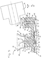
- figure 1 is a partial cross-sectional side view of an assembly according to this invention mounted on a printed circuit board;
- figure 2 is a view in the direction of
arrow 2 of figure 1; - figure 3 is a view in the direction of
arrow 3 of figure 1; - figure 4 is a partial top view of the layout of circuit traces on the printed circuit board, for connection to the connector assembly;
- figure 5 is a cross-sectional view through lines 5-5 of figure 3 showing an internal antenna connected to the connector assembly;
- figure 6 is view similar to figure 5 but showing the internal antenna in a different position due to positional tolerances.
-
- Referring to figures 1-6, a
coaxial connection assembly 2 for connecting an internal 70 or external antenna to a mobile phone, is mountable on acircuit board PCB 1 of the mobile phone. Theassembly 2 comprises a first coaxial connector 4 (or switching connector) and a second coaxial connector 6 (or internal antenna connector) that are formed together in a single assembly. Theassembly 2 has a common dielectric housing 8 (see figure 5) to which conductive contacts of theconnectors - Referring mainly to figures 5 and 2, the
switching connector 4 comprises adielectric housing portion 10, which is part of thehousing 8, within which is axially slideably mounted acenter contact 12, and mounted concentrically therearound is anouter contact 14. Theconnector 4 has amating section 16 and aconnection section 18. Theconnection section 18 comprises afirst contact leg 19 and asecond contact leg 20 mounted from aconnection side 22 of thehousing 8 into a recess 23 extending from the mounting orconnection face 22. Thecontact legs shaped barbs 24 that engage opposing walls ofvertical grooves 26 in the housing, for securing thecontacts - The
first contact leg 19 comprises a PCB connection portion in the form of asurface mount tab 28 for solder surface mount on the printedcircuit board 1, in particular to a circuit trace 31 (see figure 4) thereon. Thecontact leg 19 further comprises a spring member in the form of a cantileverbeam spring arm 30 extending from themounting portion 24 to afree end 32. Proximate thefree end 32 is a contact portion in the form of aprotrusion 34 that biases against acomplementary contact portion 36 of thesecond contact leg 20. Thespring arm 30 extends across aconnection end 38 of thecenter contact 12. Theconnection portion 38 is enlargened with respect to thebody 39 of the pin-shaped center contact such that theconnection end 38 provides anabutment 40 limiting upward biasing of thecenter contact 12 beyond amating face 42 of thehousing portion 10. Thecenter pin contact 12 is depressed towards the printed circuit board when a complementary coaxial connector is plugged to theconnector 4, thereby abutting a protrudingcontact surface 44 of thecenter pin contact 12. The complementary plugging connector is for example interconnected to a external antenna such as the antenna of an automobile whereby theswitch contacts internal antenna 70. Theouter contact 14 of theconnector 4 has a large funnel-shaped mating portion 46 having amating end 48 protruding well beyond thepin contact surface 44 for guiding and adjusting tolerances during plugging of the complementary external antenna connector to the switching connector. Theouter contact 14 is connected to circuit trace portions 50 (see figure 4) by extensions 52 (see figures 1 and 3) integrally extending axially from theconcentric portion 51 surrounding thedielectric portion 10, theextensions 52 provided withcontact pads 53 for surface mount solder connection to thecircuit traces 50. - The
antenna connector 6 comprises adielectric housing portion 56 forming part of thehousing 8 and concentrically surrounding acenter contact 58, thehousing portion 56 concentrically surrounded by anouter contact 60. Thecenter contact 58 extends from aconnection end 62 to acontact end 64, and is axially slideable in an axially extendingcavity 66 of thehousing portion 56. Thecontact end 64 has anenlargened head 67 with adomed contact surface 68 against which anantenna 70 abuts. The largedomed contact surface 68 enables theantenna 70 to be positioned significant tolerances with respect to the connector. As theantenna 70 is mounted to a housing of a cell phone, it is advantageous to allow for substantial tolerance in positioning between the housing and PCB mounted in the housing, in view of increasing reliability and reducing manufacturing costs. Thecenter contact 58 is spring mounted such that relatively large tolerances in the axial direction (A) are absorbed, (the axial direction is defined as substantially perpendicular toPCB 1 on which the connector is mountable), as can be seen by comparing figures 5 and 6. Thus, large tolerances in the radial direction R (substantially parallel to the plane of the PCB 1) and large tolerances in the axial direction A can be absorbed. - The resiliency of the second coaxial connector center contact is provided by a
spring arm 72 abutting against theconnection end 62 of thecenter contact 58. Thespring arm 72 is integrally stamped and formed with thesecond contact leg 28 which is mounted in the housing recess 23. Thespring arm 72 is in the form of a cantilever beam where the contact against theconnection end 62 is proximate afree end 74 of the arm. Thespring arm 72 also effects the electrical interconnection between thecenter contact 58 and thesecond contact leg 20 through the switch to the PCB centercontact circuit trace 31. Thecenter contact 58 comprises aretention shoulder 76 engageable with ashoulder 78 in thecavity 66 for retaining the center contact in an upwardmost position protruding beyond amating face 80 of thedielectric housing portion 56. - The
outer contact 60 of the secondcoaxial connector 6 is interconnected to the PCB by provision of acontact pad 82 soldered against a complementary semi-circular circuit trace 84 (see figure 4) that is interconnected to the outer contact circuit traces 50. Theconnectors dielectric housing 8 such that a single connector assembly can be handled and assembled to a circuit board thereby reducing assembly costs. In addition, the secure and accurate positioning of theconnector internal antenna 70 or an external antenna to thecircuit board 1 in a particularly cost-effective manner. Furthermore, theinternal antenna connector 6 absorbs large misalignments between theinternal antenna 70 and the printed circuit board by way of the enlargened dome-shapedcontact surface 68 and the axiallyslideable center contact 58 resiliently mounted against thespring arm 72. Thecontact legs common housing 8 by insertion into the recess 23 in a single insertion assembly.
Claims (12)
- A coaxial connector assembly (2) for a mobile communication device such as a phone, comprising a first coaxial connector (4) pluggably matable with a complementary coaxial antenna connector, the first connector comprising a center contact (12) matable with a center conductor of the complementary pluggable connector, the center contact actuating a switch (30, 34, 36) for disconnecting an internal antenna (70) from circuitry of the mobile phone when the complementary connector is plugged with the first connector (4), characterised in that the assembly further comprises a second coaxial connector (6) integrally formed with the first connector (4) for connection to the internal antenna (70).
- The assembly of claim 1 wherein the internal antenna connector (6) comprises a center contact (58) resiliently movable in an axial direction (A) orthogonal to a PCB (1) on which the assembly is mounted.
- The assembly of claim 2 wherein the internal antenna connector center contact (58) is slideably mounted in a cavity (66) of a dielectric housing portion (56), whereby resiliency is provided by a separate spring arm (72) engaging the center contact.
- The assembly of claim 3 wherein the spring arm (72) is stamped and formed from sheet metal.
- The assembly of claim 3 or 4 wherein the spring arm (72) is integrally formed with a second contact leg (20) having a portion (36) of the switch.
- The assembly of anyone of the preceding claims wherein the internal antenna connector center contact (58) has a large dome-shaped contact surface (68) for abutment against the internal antenna (70).
- The assembly of anyone of the preceding claims wherein the first connector has a dielectric housing portion (10) and the second connector has a dielectric housing portion (56), the housing portions (10,56) integrally formed in a common dielectric housing (8) to which contacts (12, 58, 14, 60, 19, 20) are securely mounted.
- The assembly of anyone of the preceding claims wherein the first connector (4) comprises a center contact (12) mounted slideably in an axial direction (A) with respect to a PCB (1) when the assembly is mounted thereto, the center contact having a contact surface (44) projecting beyond a mating face (42) of a dielectric housing portion (10) for abutment against the complementary pluggable connector.
- The assembly of claim 8 wherein the first connector center contact (12) engages a spring arm (30) that comprises a portion (34) of the switch.
- A coaxial connector assembly for a mobile phone, comprising an internal antenna coaxial connector (6) for connection to an internal antenna (70), the connector (6) having a dielectric housing portion (56) concentrically surrounding a pin-shaped center contact (58) slideably mounted in an axial direction (A) within a cavity (66) of the housing portion for absorbing positional tolerances of the antenna in the axial direction, the assembly further comprising a spring member (72) engaging a connection end (62) of the center contact (58) such that a contact surface (68) of the center contact is biased axially away from a mating face (80) of the dielectric housing portion (56), wherein the contact surface (68) has a large dome-shape having a diameter substantially greater than the portion of pin-shaped center contact positioned within the cavity (66) of the housing portion (56) in order to absorb tolerances in positioning an antenna (70) in a radial direction (R) substantially orthogonal to the axial direction (A).
- The assembly of claim 10 wherein the spring member is a spring arm (72) stamped and formed from sheet metal and engages a connection end (62) of the center contact opposed to the contact surface (68).
- The assembly of claim 10 or 11 wherein the spring member is integrally formed with a second contact leg (20) comprising a portion of switch (36) for disconnecting the internal antenna (70).
Priority Applications (1)
| Application Number | Priority Date | Filing Date | Title |
|---|---|---|---|
| EP98123641A EP0924810B1 (en) | 1997-12-22 | 1998-12-10 | Coaxial antenna connector for mobile phone |
Applications Claiming Priority (3)
| Application Number | Priority Date | Filing Date | Title |
|---|---|---|---|
| EP97122616 | 1997-12-22 | ||
| EP97122616 | 1997-12-22 | ||
| EP98123641A EP0924810B1 (en) | 1997-12-22 | 1998-12-10 | Coaxial antenna connector for mobile phone |
Publications (3)
| Publication Number | Publication Date |
|---|---|
| EP0924810A2 true EP0924810A2 (en) | 1999-06-23 |
| EP0924810A3 EP0924810A3 (en) | 2002-09-25 |
| EP0924810B1 EP0924810B1 (en) | 2004-04-07 |
Family
ID=26146006
Family Applications (1)
| Application Number | Title | Priority Date | Filing Date |
|---|---|---|---|
| EP98123641A Expired - Lifetime EP0924810B1 (en) | 1997-12-22 | 1998-12-10 | Coaxial antenna connector for mobile phone |
Country Status (1)
| Country | Link |
|---|---|
| EP (1) | EP0924810B1 (en) |
Cited By (5)
| Publication number | Priority date | Publication date | Assignee | Title |
|---|---|---|---|---|
| GB2351617A (en) * | 1999-06-30 | 2001-01-03 | Matsushita Electric Ind Co Ltd | Coaxial connector with switch |
| EP1158627A1 (en) * | 1999-12-27 | 2001-11-28 | Yamaichi Electrics Co., Ltd. | Coaxial connector with switch |
| WO2002049408A1 (en) * | 2000-12-12 | 2002-06-20 | Testo Ag | Module for measuring purposes |
| EP1460771A1 (en) * | 2003-03-19 | 2004-09-22 | Sony Ericsson Mobile Communications AB | A switchable antenna arrangement |
| WO2004084427A1 (en) * | 2003-03-19 | 2004-09-30 | Sony Ericsson Mobile Communications Ab | A switchable antenna arrangement |
Citations (1)
| Publication number | Priority date | Publication date | Assignee | Title |
|---|---|---|---|---|
| US4286335A (en) * | 1979-11-08 | 1981-08-25 | Motorola, Inc. | Coaxial dual antenna connection arrangement for communications apparatus |
-
1998
- 1998-12-10 EP EP98123641A patent/EP0924810B1/en not_active Expired - Lifetime
Patent Citations (1)
| Publication number | Priority date | Publication date | Assignee | Title |
|---|---|---|---|---|
| US4286335A (en) * | 1979-11-08 | 1981-08-25 | Motorola, Inc. | Coaxial dual antenna connection arrangement for communications apparatus |
Cited By (10)
| Publication number | Priority date | Publication date | Assignee | Title |
|---|---|---|---|---|
| GB2351617A (en) * | 1999-06-30 | 2001-01-03 | Matsushita Electric Ind Co Ltd | Coaxial connector with switch |
| US6320144B1 (en) | 1999-06-30 | 2001-11-20 | Matsushita Electric Industrial Co., Ltd. | Coaxial connector switch |
| GB2351617B (en) * | 1999-06-30 | 2003-05-14 | Matsushita Electric Ind Co Ltd | Switched coaxial connector |
| EP1158627A1 (en) * | 1999-12-27 | 2001-11-28 | Yamaichi Electrics Co., Ltd. | Coaxial connector with switch |
| EP1158627A4 (en) * | 1999-12-27 | 2007-09-05 | Yamaichi Electronics Co Ltd | Coaxial connector with switch |
| WO2002049408A1 (en) * | 2000-12-12 | 2002-06-20 | Testo Ag | Module for measuring purposes |
| EP1460771A1 (en) * | 2003-03-19 | 2004-09-22 | Sony Ericsson Mobile Communications AB | A switchable antenna arrangement |
| WO2004084427A1 (en) * | 2003-03-19 | 2004-09-30 | Sony Ericsson Mobile Communications Ab | A switchable antenna arrangement |
| US7511681B2 (en) | 2003-03-19 | 2009-03-31 | Sony Ericsson Mobile Communications Ab | Switchable antenna arrangement |
| CN1792041B (en) * | 2003-03-19 | 2010-12-08 | 索尼爱立信移动通讯股份有限公司 | Antenna apparatus, method for controlling antenna reception mode and mobile radio terminal |
Also Published As
| Publication number | Publication date |
|---|---|
| EP0924810A3 (en) | 2002-09-25 |
| EP0924810B1 (en) | 2004-04-07 |
Similar Documents
| Publication | Publication Date | Title |
|---|---|---|
| US6224407B1 (en) | Coaxial switch connector assembly | |
| US6758680B2 (en) | Coaxial connector for interconnecting printed circuit boards | |
| JP3970939B2 (en) | Coaxial switch connector assembly | |
| KR100367071B1 (en) | Cordless phone cradle connector | |
| US6155848A (en) | Auxiliary device for ZIF electrical connector | |
| EP0970547B1 (en) | Coaxial connector for circuit board | |
| KR101802731B1 (en) | Coaxial connector with switch | |
| JP2838135B2 (en) | Thin receptacle connector | |
| US6142803A (en) | Coaxial antenna connector for mobile phone | |
| US6473045B1 (en) | Coaxial connector assembly and antenna assembly having a switching function | |
| EP1846986A2 (en) | Novel coaxial connector | |
| WO1998005103A1 (en) | Electrical connector | |
| US6435892B1 (en) | Electrical connector with a supporting mechanism | |
| EP0924810B1 (en) | Coaxial antenna connector for mobile phone | |
| US6171123B1 (en) | Electrical connector | |
| US6837724B2 (en) | Electrical connector with an internal switch | |
| US20020115318A1 (en) | Electrical connector and circuit with center ground plane | |
| WO2021215143A1 (en) | Connector device | |
| KR102309404B1 (en) | Board to board connector | |
| CN112448209B (en) | Shielded connector | |
| CN115398752A (en) | Connector assembly | |
| CN217405782U (en) | Plug connector and connector assembly | |
| CN112103697B (en) | Electrical connector | |
| GB2336480A (en) | Coaxial switching connector | |
| CN107887735B (en) | Coaxial connector |
Legal Events
| Date | Code | Title | Description |
|---|---|---|---|
| PUAI | Public reference made under article 153(3) epc to a published international application that has entered the european phase |
Free format text: ORIGINAL CODE: 0009012 |
|
| AK | Designated contracting states |
Kind code of ref document: A2 Designated state(s): AT BE CH CY DE DK ES FI FR GB GR IE IT LI LU MC NL PT SE |
|
| AX | Request for extension of the european patent |
Free format text: AL;LT;LV;MK;RO;SI |
|
| PUAL | Search report despatched |
Free format text: ORIGINAL CODE: 0009013 |
|
| AK | Designated contracting states |
Kind code of ref document: A3 Designated state(s): AT BE CH CY DE DK ES FI FR GB GR IE IT LI LU MC NL PT SE |
|
| AX | Request for extension of the european patent |
Free format text: AL;LT;LV;MK;RO;SI |
|
| RIC1 | Information provided on ipc code assigned before grant |
Free format text: 7H 01R 13/646 A |
|
| 17P | Request for examination filed |
Effective date: 20030220 |
|
| 17Q | First examination report despatched |
Effective date: 20030410 |
|
| AKX | Designation fees paid |
Designated state(s): CH DE FI FR GB LI SE |
|
| GRAP | Despatch of communication of intention to grant a patent |
Free format text: ORIGINAL CODE: EPIDOSNIGR1 |
|
| GRAS | Grant fee paid |
Free format text: ORIGINAL CODE: EPIDOSNIGR3 |
|
| GRAA | (expected) grant |
Free format text: ORIGINAL CODE: 0009210 |
|
| AK | Designated contracting states |
Kind code of ref document: B1 Designated state(s): CH DE FI FR GB LI SE |
|
| REG | Reference to a national code |
Ref country code: GB Ref legal event code: FG4D |
|
| REG | Reference to a national code |
Ref country code: SE Ref legal event code: TRGR |
|
| REG | Reference to a national code |
Ref country code: CH Ref legal event code: EP |
|
| REF | Corresponds to: |
Ref document number: 69822989 Country of ref document: DE Date of ref document: 20040513 Kind code of ref document: P |
|
| REG | Reference to a national code |
Ref country code: CH Ref legal event code: NV Representative=s name: RITSCHER & PARTNER AG PATENTANWAELTE |
|
| ET | Fr: translation filed | ||
| PLBE | No opposition filed within time limit |
Free format text: ORIGINAL CODE: 0009261 |
|
| STAA | Information on the status of an ep patent application or granted ep patent |
Free format text: STATUS: NO OPPOSITION FILED WITHIN TIME LIMIT |
|
| 26N | No opposition filed |
Effective date: 20050110 |
|
| PGFP | Annual fee paid to national office [announced via postgrant information from national office to epo] |
Ref country code: FR Payment date: 20061220 Year of fee payment: 9 |
|
| PGFP | Annual fee paid to national office [announced via postgrant information from national office to epo] |
Ref country code: GB Payment date: 20061222 Year of fee payment: 9 |
|
| PGFP | Annual fee paid to national office [announced via postgrant information from national office to epo] |
Ref country code: SE Payment date: 20061227 Year of fee payment: 9 Ref country code: CH Payment date: 20061227 Year of fee payment: 9 |
|
| PGFP | Annual fee paid to national office [announced via postgrant information from national office to epo] |
Ref country code: FI Payment date: 20061228 Year of fee payment: 9 |
|
| PGFP | Annual fee paid to national office [announced via postgrant information from national office to epo] |
Ref country code: DE Payment date: 20070131 Year of fee payment: 9 |
|
| REG | Reference to a national code |
Ref country code: CH Ref legal event code: PCAR Free format text: RITSCHER & PARTNER AG;RESIRAIN 1;8125 ZOLLIKERBERG (CH) |
|
| PG25 | Lapsed in a contracting state [announced via postgrant information from national office to epo] |
Ref country code: FI Free format text: LAPSE BECAUSE OF NON-PAYMENT OF DUE FEES Effective date: 20071210 |
|
| REG | Reference to a national code |
Ref country code: CH Ref legal event code: PL |
|
| EUG | Se: european patent has lapsed | ||
| GBPC | Gb: european patent ceased through non-payment of renewal fee |
Effective date: 20071210 |
|
| PG25 | Lapsed in a contracting state [announced via postgrant information from national office to epo] |
Ref country code: SE Free format text: LAPSE BECAUSE OF NON-PAYMENT OF DUE FEES Effective date: 20071211 Ref country code: LI Free format text: LAPSE BECAUSE OF NON-PAYMENT OF DUE FEES Effective date: 20071231 Ref country code: DE Free format text: LAPSE BECAUSE OF NON-PAYMENT OF DUE FEES Effective date: 20080701 Ref country code: CH Free format text: LAPSE BECAUSE OF NON-PAYMENT OF DUE FEES Effective date: 20071231 |
|
| REG | Reference to a national code |
Ref country code: FR Ref legal event code: ST Effective date: 20081020 |
|
| PG25 | Lapsed in a contracting state [announced via postgrant information from national office to epo] |
Ref country code: GB Free format text: LAPSE BECAUSE OF NON-PAYMENT OF DUE FEES Effective date: 20071210 |
|
| PG25 | Lapsed in a contracting state [announced via postgrant information from national office to epo] |
Ref country code: FR Free format text: LAPSE BECAUSE OF NON-PAYMENT OF DUE FEES Effective date: 20071231 |