EP0924779A1 - Non-aqueous electrolyte secondary battery - Google Patents
Non-aqueous electrolyte secondary battery Download PDFInfo
- Publication number
- EP0924779A1 EP0924779A1 EP98124035A EP98124035A EP0924779A1 EP 0924779 A1 EP0924779 A1 EP 0924779A1 EP 98124035 A EP98124035 A EP 98124035A EP 98124035 A EP98124035 A EP 98124035A EP 0924779 A1 EP0924779 A1 EP 0924779A1
- Authority
- EP
- European Patent Office
- Prior art keywords
- battery
- aqueous electrolyte
- electrolyte secondary
- secondary battery
- electrode
- Prior art date
- Legal status (The legal status is an assumption and is not a legal conclusion. Google has not performed a legal analysis and makes no representation as to the accuracy of the status listed.)
- Granted
Links
Images



Classifications
-
- H—ELECTRICITY
- H01—ELECTRIC ELEMENTS
- H01M—PROCESSES OR MEANS, e.g. BATTERIES, FOR THE DIRECT CONVERSION OF CHEMICAL ENERGY INTO ELECTRICAL ENERGY
- H01M10/00—Secondary cells; Manufacture thereof
- H01M10/05—Accumulators with non-aqueous electrolyte
- H01M10/058—Construction or manufacture
- H01M10/0585—Construction or manufacture of accumulators having only flat construction elements, i.e. flat positive electrodes, flat negative electrodes and flat separators
-
- H—ELECTRICITY
- H01—ELECTRIC ELEMENTS
- H01M—PROCESSES OR MEANS, e.g. BATTERIES, FOR THE DIRECT CONVERSION OF CHEMICAL ENERGY INTO ELECTRICAL ENERGY
- H01M10/00—Secondary cells; Manufacture thereof
- H01M10/04—Construction or manufacture in general
- H01M10/0436—Small-sized flat cells or batteries for portable equipment
-
- H—ELECTRICITY
- H01—ELECTRIC ELEMENTS
- H01M—PROCESSES OR MEANS, e.g. BATTERIES, FOR THE DIRECT CONVERSION OF CHEMICAL ENERGY INTO ELECTRICAL ENERGY
- H01M50/00—Constructional details or processes of manufacture of the non-active parts of electrochemical cells other than fuel cells, e.g. hybrid cells
- H01M50/10—Primary casings; Jackets or wrappings
- H01M50/102—Primary casings; Jackets or wrappings characterised by their shape or physical structure
- H01M50/103—Primary casings; Jackets or wrappings characterised by their shape or physical structure prismatic or rectangular
-
- H—ELECTRICITY
- H01—ELECTRIC ELEMENTS
- H01M—PROCESSES OR MEANS, e.g. BATTERIES, FOR THE DIRECT CONVERSION OF CHEMICAL ENERGY INTO ELECTRICAL ENERGY
- H01M50/00—Constructional details or processes of manufacture of the non-active parts of electrochemical cells other than fuel cells, e.g. hybrid cells
- H01M50/10—Primary casings; Jackets or wrappings
- H01M50/172—Arrangements of electric connectors penetrating the casing
- H01M50/174—Arrangements of electric connectors penetrating the casing adapted for the shape of the cells
-
- H—ELECTRICITY
- H01—ELECTRIC ELEMENTS
- H01M—PROCESSES OR MEANS, e.g. BATTERIES, FOR THE DIRECT CONVERSION OF CHEMICAL ENERGY INTO ELECTRICAL ENERGY
- H01M50/00—Constructional details or processes of manufacture of the non-active parts of electrochemical cells other than fuel cells, e.g. hybrid cells
- H01M50/50—Current conducting connections for cells or batteries
- H01M50/572—Means for preventing undesired use or discharge
- H01M50/574—Devices or arrangements for the interruption of current
- H01M50/578—Devices or arrangements for the interruption of current in response to pressure
-
- H—ELECTRICITY
- H01—ELECTRIC ELEMENTS
- H01M—PROCESSES OR MEANS, e.g. BATTERIES, FOR THE DIRECT CONVERSION OF CHEMICAL ENERGY INTO ELECTRICAL ENERGY
- H01M50/00—Constructional details or processes of manufacture of the non-active parts of electrochemical cells other than fuel cells, e.g. hybrid cells
- H01M50/50—Current conducting connections for cells or batteries
- H01M50/572—Means for preventing undesired use or discharge
- H01M50/574—Devices or arrangements for the interruption of current
- H01M50/581—Devices or arrangements for the interruption of current in response to temperature
-
- H—ELECTRICITY
- H01—ELECTRIC ELEMENTS
- H01M—PROCESSES OR MEANS, e.g. BATTERIES, FOR THE DIRECT CONVERSION OF CHEMICAL ENERGY INTO ELECTRICAL ENERGY
- H01M50/00—Constructional details or processes of manufacture of the non-active parts of electrochemical cells other than fuel cells, e.g. hybrid cells
- H01M50/60—Arrangements or processes for filling or topping-up with liquids; Arrangements or processes for draining liquids from casings
- H01M50/609—Arrangements or processes for filling with liquid, e.g. electrolytes
- H01M50/627—Filling ports
-
- H—ELECTRICITY
- H01—ELECTRIC ELEMENTS
- H01M—PROCESSES OR MEANS, e.g. BATTERIES, FOR THE DIRECT CONVERSION OF CHEMICAL ENERGY INTO ELECTRICAL ENERGY
- H01M50/00—Constructional details or processes of manufacture of the non-active parts of electrochemical cells other than fuel cells, e.g. hybrid cells
- H01M50/30—Arrangements for facilitating escape of gases
-
- H—ELECTRICITY
- H01—ELECTRIC ELEMENTS
- H01M—PROCESSES OR MEANS, e.g. BATTERIES, FOR THE DIRECT CONVERSION OF CHEMICAL ENERGY INTO ELECTRICAL ENERGY
- H01M50/00—Constructional details or processes of manufacture of the non-active parts of electrochemical cells other than fuel cells, e.g. hybrid cells
- H01M50/50—Current conducting connections for cells or batteries
- H01M50/543—Terminals
- H01M50/552—Terminals characterised by their shape
- H01M50/553—Terminals adapted for prismatic, pouch or rectangular cells
-
- H—ELECTRICITY
- H01—ELECTRIC ELEMENTS
- H01M—PROCESSES OR MEANS, e.g. BATTERIES, FOR THE DIRECT CONVERSION OF CHEMICAL ENERGY INTO ELECTRICAL ENERGY
- H01M6/00—Primary cells; Manufacture thereof
- H01M6/40—Printed batteries, e.g. thin film batteries
-
- Y—GENERAL TAGGING OF NEW TECHNOLOGICAL DEVELOPMENTS; GENERAL TAGGING OF CROSS-SECTIONAL TECHNOLOGIES SPANNING OVER SEVERAL SECTIONS OF THE IPC; TECHNICAL SUBJECTS COVERED BY FORMER USPC CROSS-REFERENCE ART COLLECTIONS [XRACs] AND DIGESTS
- Y02—TECHNOLOGIES OR APPLICATIONS FOR MITIGATION OR ADAPTATION AGAINST CLIMATE CHANGE
- Y02E—REDUCTION OF GREENHOUSE GAS [GHG] EMISSIONS, RELATED TO ENERGY GENERATION, TRANSMISSION OR DISTRIBUTION
- Y02E60/00—Enabling technologies; Technologies with a potential or indirect contribution to GHG emissions mitigation
- Y02E60/10—Energy storage using batteries
-
- Y—GENERAL TAGGING OF NEW TECHNOLOGICAL DEVELOPMENTS; GENERAL TAGGING OF CROSS-SECTIONAL TECHNOLOGIES SPANNING OVER SEVERAL SECTIONS OF THE IPC; TECHNICAL SUBJECTS COVERED BY FORMER USPC CROSS-REFERENCE ART COLLECTIONS [XRACs] AND DIGESTS
- Y02—TECHNOLOGIES OR APPLICATIONS FOR MITIGATION OR ADAPTATION AGAINST CLIMATE CHANGE
- Y02P—CLIMATE CHANGE MITIGATION TECHNOLOGIES IN THE PRODUCTION OR PROCESSING OF GOODS
- Y02P70/00—Climate change mitigation technologies in the production process for final industrial or consumer products
- Y02P70/50—Manufacturing or production processes characterised by the final manufactured product
Definitions
- the present invention relates to a non-aqueous electrolyte secondary battery for use in a power source for a portable electronic apparatus or the like, and more particularly to an improvement in the shape of a battery.
- hydraulic electrolyte secondary batteries have been employed which include nickel-cadmium batteries.
- the foregoing hydraulic electrolyte secondary batteries suffer from excessively low discharge potentials. What is worse, the weight and volume of the battery cannot satisfactorily be reduced. Thus, a requirement for raising the energy density cannot be met.
- non-aqueous electrolyte secondary batteries such as lithium ion secondary batteries, have been suggested and put to practical use because of their higher energy densities than those of the hydraulic electrolyte secondary batteries.
- the non-aqueous electrolyte secondary batteries have been formed into cylindrical batteries each having an electrode device wound into a spiral shape and inserted into a cylindrical battery can; laminated electrode devices formed by laminating folded electrodes or positive and negative electrodes in the form of rectangles; and rectangular batteries each of which is formed by inserting, into a rectangular battery can, a coil electrode device constituted by winding elongated positive and negative electrodes.
- the rectangular battery has a space efficiency superior to that of the cylindrical battery.
- each portable electronic apparatus has furthermore been reduced. Also the thicknesses of the apparatuses have been reduced. It leads to a fact that reduction in the thickness of the second batteries serving as the power sources for the electronic apparatuses has been required.
- the thickness of an electrode device 22 which must be accommodated in the battery can 21 is reduced.
- the hardness of the electrode device 22 decreases in a direction indicated by an arrow X shown in Fig. 1. Therefore, there arises a problem when the electrode device 22 is inserted into the battery can 21 in a direction (indicated by an arrow Y shown in Fig. 1) in parallel with a direction in which the electrodes are stacked. That is, the electrode device 22 is undesirably deformed because of contact resistance caused between the electrode device 22 and the inner surface of the battery can 21, as shown in Fig. 2. As a result, the electrode device 22 cannot easily and smoothly be inserted into the battery can 21.
- the terminal cannot easily be formed on a battery cover which is provided for the surface of the battery can having the minimum area. In this case, a space for a safety unit, such as a split valve, cannot easily be obtained. Moreover, a lead wire which must be drawn out from the terminal of the battery to an electronic apparatus cannot easily be welded.
- the thickness of the electrode device is reduced.
- the clearance between the battery can and the electrode device is enlarged in order to reduce the contact resistance.
- pressure which can be applied to the electrode device is, however, lowered.
- force for bringing the positive electrode and the negative electrode into hermetic contact with each other is reduced.
- movement and reactions of ions cannot smoothly be performed.
- an object of the present invention is to provide a non-aqueous electrolyte secondary battery having a structure with which an electrode device can easily be inserted into a battery can thereof and a terminal can easily be formed even if the thickness of the battery is considerably reduced.
- a non-aqueous electrolyte secondary battery comprising: a battery can which accommodates an electrode device and non-aqueous electrolyte, wherein a largest opening of the battery can is hermetically sealed by a battery cover incorporating a terminal.
- the battery cover has a safety unit which outwards releases internal pressure of the battery when the internal pressure of the battery has been raised to a predetermined pressure.
- the safety unit incorporates at least a member, which is selected from a group consisting of a current interrupting unit and a Positive Temperature Coefficient device, and a split valve.
- the battery cover has an electrolyte injecting opening through which the electrolyte is injected.
- the electrode device is formed into a laminate constituted by laminating a positive electrode and a negative electrode substantially in parallel with the battery cover through a separator.
- leads drawn out from the electrode device and laid substantially in parallel with the battery cover are connected to the terminal.
- the battery can is formed into a rectangular shape.
- the height of the battery can from a bottom surface thereof to the battery cover is 0.5 mm to 6 mm.
- the non-aqueous electrolyte secondary battery according to the present invention incorporates an electrode device 2 accommodated through a largest opening 1a of a battery can 1 formed into a flat and rectangular shape.
- the largest opening 1a is hermetically sealed by a battery cover 4 which incorporates a terminal 3.
- the electrode device 2 incorporates a positive electrode 5 and a negative electrode 6 formed into rectangular shapes and laminated through a separator 7.
- a collecting plate 8 and a pressing plate 9 are disposed at two ends of the electrode device 2.
- a device-bonding tape 10 is used to secure the end portion of the electrode device 2.
- the electrode device 2 is inserted into the battery can 1 through the largest opening 1a of the battery can 1 in a direction indicated by an arrow X.
- the electrode device 2, a device-pressing plate 11 and an insulating plate 12 are collectively inserted into the battery can 1.
- the electrode device 2 may be either of a laminated electrode device formed by laminating a plurality of combinations of plate-like positive and negative electrodes or a coil-type electrode device formed by turning elongated positive and negative electrodes.
- the battery cover 4 is provided with the terminal 3, a split valve 14 and an electrolyte injecting opening 15 disposed on a surface of the battery cover 4 opposite to the electrode device 2.
- the terminal 3 is joined to the battery cover 4 through an insulating portion 16. An end of the terminal 3 is electrically connected to the positive electrode 5 in the battery can 1 through a positive-electrode lead 17. Another end of the terminal 3 is electrically connected to an external connecting terminal so that a positive terminal is formed. On the other hand, a negative-electrode lead 18 drawn out from the negative electrode 6 is electrically connected to the battery can 1 through the collecting plate 8. Thus, the battery can 1 has a polarity which is different from that of the terminal 3.
- the positive-electrode lead 17 and the negative-electrode lead 18 are drawn out in direction Y in which the electrode device 2 is laminated, that is, substantially in parallel with the battery cover 4. Then, the positive-electrode lead 17 and the negative-electrode lead 18 are connected by welding or the like in parallel with the connecting surface of the terminal 3 or the battery can 1.
- the split valve 14 is constituted by metal foil, such as nickel foil, structured to have a splitting pressure adjusted to a predetermined pressure. If the pressure in the battery can 1 is raised for some reason, the split valve 14 is split. Thus, the pressure in the battery can 1 is directly released to the outside of the non-aqueous electrolyte secondary battery.
- the electrolyte injecting opening 15 is an opening through which the electrolyte is injected into the battery can 1. After the battery has been assembled, the electrolyte injecting opening 15 is welded by resistance welding or the like so as to be sealed.
- the battery cover 4 structured as described above may have a current interrupting mechanism for interrupting an electric current if the pressure in the battery can 1 is raised.
- a Positive Temperature Coefficient device may be provided which interrupts an electric current because resistance thereof is increased if the temperature is raised.
- the battery cover 4 is joined to the largest opening 1a of the battery can 1.
- the battery cover 4 may be joined as described above by welding, as shown in Fig. 3.
- the outer end of the battery cover 4 and the periphery of the opening of the terminal 3 may be caulked. Note that the same elements in Fig. 7 are given the same reference numerals and the same elements are omitted from description.
- the battery can 1 may be made of any one of known materials. For example, iron, nickel, stainless steel, aluminum or their alloy may be employed. If corrosion takes place owning to the non-aqueous electrolyte, plating may be performed.
- the battery can 1 can be manufactured by any one of appropriate methods. For example, a drawing process may be employed such that a nickel-plated steel plate is subjected to an ironing process using a mold.
- the battery cover 4 may be made of any one of known materials including iron, nickel, stainless steel, aluminum and their alloy. If corrosion takes place owning to the non-aqueous electrolyte, plating may be performed.
- the battery cover 4 can be manufactured by any one of known methods. For example, a nickel-plated steel plate is molded by a pressing work. Then, the terminal 3 is caulked. Thus, the battery cover 4 having the terminal 3 can be manufactured. It is preferable that the split valve 14 is provided for the battery cover 4 before or after the pressing work or after the terminal 3 has been formed.
- the electrode device 2 of the non-aqueous electrolyte secondary battery structured as described above is inserted through the largest opening 1a of the battery can 1 in a direction indicated by an arrow X.
- the height from a bottom surface 1b to the battery cover 4, that is, the height of the battery in the direction X (hereinafter called thickness x of the battery) is very small. Therefore, the electrode device 2 is not deformed by the contact resistance. As a result, the electrode device 2 can easily and smoothly be inserted.
- clearance k can be created between the battery can 1 and the electrode device 2, as shown in Fig. 5. Therefore, the electrode device 2 can easily and smoothly be inserted into the battery can 1.
- the largest opening 1a of the battery can 1 is hermetically sealed by the battery cover 4. Therefore, the productivity can be improved.
- the non-aqueous electrolyte secondary battery has the large battery cover 4. Therefore, the terminal 3 can significantly easily be formed. Moreover, the safety unit including the split valve 14 can be provided for the battery cover 4. As a result, the productivity and reliability can be improved.
- the non-aqueous electrolyte secondary battery according to the present invention is structured such that the largest opening 1a of the battery can 1 is hermetically sealed by the battery cover 4 having the terminal 3. Therefore, the thickness of the battery can be reduced.
- the thickness x of the battery is 0.5 mm or greater, more preferably 0.6 mm or greater. If the thickness x of the battery is smaller than 0.5 mm, the strength of the battery decreases.
- the thickness x of the battery is 6 mm or smaller, more preferably 5 mm or smaller. If the thickness x of the battery is greater than 6 mm, the electrode device 2 is able to have sufficient strength. Therefore, the electrode device 2 can easily be inserted also through the opening which is the smallest area of the battery can 1. In the foregoing case, the advantage that the largest opening 1a is provided for the largest surface of the battery can 1 cannot be obtained.
- the structure of the present invention is applied to a lithium secondary battery or a lithium ion secondary battery, the following materials may be employed.
- positive-electrode active materials for making the positive electrode 5 contain lithium in a sufficiently large quantity.
- a composite metal oxide may be employed which contains lithium expressed by general formula LiMO 2 (where M is at least any one of Co, Ni, Mn, Fe, Al, V and Ti) and transition metal.
- an interlayer compound may be employed which contains lithium.
- Negative electrode active materials for making the negative electrode 6 may be any one of oxides having relatively basic potential, such as iron oxide, ruthenium oxide, molybdenum oxide, tungsten oxide or titanium oxide.
- the negative electrode active materials may be a carbon material permitting doping/dedoping of lithium, lithium alloy and lithium ions.
- the carbon material for making the negative electrode 6 may be any one of the following materials: a conjugate resin, such as a phenol resin, an acrylic resin, a vinyl halide resin, a polyimide resin, a polyamideimide resin, a polyamide resin, polyacetylene or poly (p-phenylene); a cellulose derivative; its derivative; and an arbitrary organic polymer compound.
- a conjugate resin such as a phenol resin, an acrylic resin, a vinyl halide resin, a polyimide resin, a polyamideimide resin, a polyamide resin, polyacetylene or poly (p-phenylene); a cellulose derivative; its derivative; and an arbitrary organic polymer compound.
- a carbonaceous material or graphite may be employed which includes a furan resin composed of homopolymers or copolymers of furfuryl alcohol or furfural; or petroleum pitch, which can be prepared by performing carbonating such that the foregoing organic material is, for example, baked.
- the electrolyte may be non-aqueous electrolyte having a structure that electrolyte is dissolved in non-aqueous solvent
- the non-aqueous solvent may be any one of the following materials: propylene carbonate, ethylene carbonate, butylene carbonate, diethyl carbonate, dimethyl carbonate, methylethyl carbonate, 1, 2-dimethoxyethane, 1, 2-diethoxymethane, ⁇ -butyrolactone, valerolactone, tetrahydrofuran, 2-methyltetrahydrofuran, 1, 3-dioxolan, 4-methyl-1, 3-dioxolan, sulfolane, methylsulfolane, acetonitrile, propyonitrile and their mixture.
- the electrolyte which can be dissolved in the above-mentioned non-aqueous solvent may be any one of known materials. It is preferable that any one of the following materials is employed: LiPF 6 , LiClO 4 , LiAsF 6 , LiBF 4 , LiB(C 6 H 5 ) 4 , CH 3 SO 3 Li, CF 3 SO 3 Li, LiN (CF 3 SO 2 ) 3 , LiC(CF 3 SO 2 ) 3 , LiCl and LiBr. It is preferable that LiPF 6 is employed.
- a flat and rectangle secondary battery shown in Fig. 3 is manufactured.
- the positive electrode 5 is manufactured as follows.
- a positive electrode active substance which is 94.5 parts by weight of lithium cobalt oxide (LiCoO 2 ), 3 parts by weight of ketchen black serving as a conductive material and 2.5 parts by weight of polyvinylidene fluoride are mixed. Then, dimethylformamide serving as a dispersant is added so that a slurry material is prepared. Then the slurry is dried with hot air, the temperature of which is 150°C by using a spray driver (manufactured by Sakamoto) for organic solvent. Thus, substantially complete spherical powder having an average particle size of 100 ⁇ is prepared. The thus-prepared granule mixture is molded into a rectangular shape.
- a collector in the form of an aluminum mesh is interposed between the molded mixtures, and then molding is performed to form a rectangular shape.
- an elongated positive electrode having a volume density of 3.1 g/ml and size of 39.5 mm ⁇ 31.0 mm is obtained.
- a positive electrode lead constituted by aluminum foil having a thickness of 10 ⁇ m has been connected to the collector by ultrasonic welding.
- the thickness of the elongated positive electrode 5 is 0.8 mm.
- the negative electrode 6 is manufactured as follows.
- Low-expansion mesophase carbon powder containing fixed carbon by 88.5 % and having a total expansion ratio of 0 % (measured by a dilatometer for use in a heat expansion test for coal) under 250 mesh is processed at 300°C for one hour in an oxidation atmosphere.
- carbonaceous powder a having an average particle size of 20 ⁇ is obtained.
- Low-expansion mesophase carbon powder containing fixed carbon by 88.5 % and having a total expansion ratio of 0% (measured by a dilatometer for use in a heat expansion test for coal) under 250 mesh is processed at 300°C for one hour in an oxidation atmosphere. Then, the atmosphere is changed to an inert (nitrogen) gas. In the inert gas atmosphere, the material is baked at 900°C for 3 hours so that a material in the form of coke is obtained which is then pulverized. As a result, carbonaceous powder b having an average particle size of 20 ⁇ is obtained.
- the carbonaceous powder a and the carbonaceous powder b are mixed at a ratio of 70:30. Then, polyvinyl alcohol (having molecular weight of 500) serving as a binder is added. Water is employed as the solvent for a kneading process. Then, a mesh not less than 150 ⁇ nor more than 250 ⁇ is employed to perform granulation and adjust the grain size.
- an elongated negative electrode made of a sintered body having a size of 41.5 mm ⁇ 32.0 mm is obtained.
- the volume density of the carbonaceous portion of the negative electrode 6 was 1.25 g/ml and the true specific gravity was 1.75 g/ml.
- the thickness of the elongated negative electrode 6 is 0.35 mm.
- the manufactured positive electrodes 5 and the negative electrodes 6 are laminated through separators 7 in the form of micro-porous polyethylene films each having a thickness of 30 ⁇ m.
- the laminating order is such that the negative electrode 6, the separator 7, the positive electrode 5, the separator 7 and the negative electrode 6 are sequentially laminated in this sequential order (that is, two negative electrodes, one positive electrode and two separators are provided).
- the collecting plate 8 and the pressing plate 9 are disposed at two ends of the obtained laminate.
- a device-bonding tape 10 having a width of 40 mm is used to secure the ends.
- the electrode device 2 is manufactured.
- To collect electric currents from the negative electrode 6, the negative-electrode leads 18 are bundled, and then welded to an end of the collecting plate 8.
- To collect electric currents from the positive electrode 5 an end of the positive-electrode lead 17 is welded to the terminal 3 joined to the battery cover 4.
- the electrode device 2, the device-pressing plate 11 and the insulating plate 12 are accommodated in a flat and rectangle battery can 1 made of iron subjected to nickel plating.
- the collecting plate 8 is brought into contact with the battery can 1.
- the battery can 1 and the battery cover 4 are secured to each other by laser welding.
- non-aqueous electrolyte in which one mole of LiPF 6 is dissolved in mixture solvent composed of 50 vol% propylene carbonate and 50 vol% diethylcarbonate is injected through the electrolyte injecting opening 15. Then, the electrolyte injecting opening 15 is welded so that gastightness in the battery is realized.
- a flat and rectangular secondary battery which has a thickness x (height from the bottom surface of the battery can 1 to the battery cover 4) of 3mm, a height of 48 mm and a width of 34 mm.
- Two positive electrodes 5 each having a thickness of 0.8 mm are prepared.
- Three negative electrodes 6 are prepared which consist of two negative electrodes 6 each having a thickness of 0.35 mm and arranged to be disposed at the outermost positions and one negative electrode 6 having a thickness of 0.65 mm.
- the positive electrodes 5 and the negative electrodes 6 are laminated through four separators 7. Thus, the electrode device 2 is manufactured.
- a non-aqueous electrolyte secondary battery according to Example 2 of the present invention is manufactured similarly to Example 1 except for the above-mentioned electrode device 2.
- the non-aqueous electrolyte secondary battery according to this example is a flat and rectangular battery having a thickness x of 4.5 mm, a height of 48 mm and a width of 34 mm. Note that the battery can 1 must correspond to the designed thickness.
- Three positive electrodes 5 each having a thickness of 0.8 mm are prepared.
- Four negative electrodes 6 are prepared which consist of two negative electrodes 6 each having a thickness of 0.35 mm and arranged to be disposed at the outermost positions and two negative electrodes 6 each having a thickness of 0.65 mm.
- the positive electrodes 5 and the negative electrodes 6 are laminated through six separators 7 so that the electrode device 2 is manufactured.
- the non-aqueous electrolyte secondary battery according to Example 3 of the present invention is manufactured similarly to Example 1 except for the above-mentioned electrode device 2.
- the non-aqueous electrolyte secondary battery according to this example is a flat and rectangular secondary battery having a thickness x of 6mm, a height of 48 mm and a width of 34 mm. Note that the battery can 1 must correspond to the deigned thickness.
- Example 4 of the present invention a molded positive electrode having size of 39.5 mm ⁇ 30.0 mm is employed to serve as the positive electrode.
- a molded negative electrode having size of 41.5 mm ⁇ 31.0 mm is employed.
- the battery can 1 and the battery cover 4 are secured to each other by caulking so that a flat and rectangular secondary battery (see Fig. 7) is manufactured.
- the other structure of the battery according to this example are similar to those of Example 1.
- the battery can 1 must correspond to the designed thickness.
- a battery according to Comparative Example 1 is a flat and rectangular secondary battery (see Fig. 7) incorporating a battery can 21 having an opening 21a formed in the surface having a smallest area thereof.
- a terminal 24 is joined through an insulating portion 23.
- the other structures of the battery according to this comparative example are similar to those according to Example 1.
- a battery according to Comparative Example 2 is a flat and rectangular secondary battery incorporating a battery can which is a battery can 21 having an opening 21a formed in the surface having a smallest area. Moreover, the battery incorporates a battery cover 25 to which a terminal 24 is joined to hermetically seal the opening 21a through an insulating portion 23.
- the other structures of the battery according to this comparative example are similar to those according to Example 2.
- a battery according to Comparative Example 3 is a flat and rectangular secondary battery incorporating a battery can 21 having an opening 21a formed in the surface having a smallest area. Moreover, a battery can 25 is employed which hermetically seal the opening 21a and to which a terminal 24 is joined through an insulating portion 23.
- the other structures of the battery according to this comparative example are similar to those according to Example 3.
- the flat and rectangular secondary batteries according to Example 1 to 4 and having the structure that the largest opening 1a of the battery can 1 is hermetically sealed by the battery cover 4 having the terminal 3 enables the electrode device 2 to easily be inserted into the battery can 1 even if the thickness x of the battery is reduced. The insertion of the electrode device 2 can satisfactorily be performed. Thus, batteries exhibiting excellent productivity can be obtained.
- the flat and rectangular secondary batteries according to Comparative Examples 1 to 3 and having the structure that the minimum opening 21a of the battery can 21 is hermetically sealed by the battery cover 25 having the terminal 24 results in difficulty in inserting the electrode device 2 into the battery can 21 when the thickness x of the battery is reduced. That is, insertion of the electrode device cannot easily and smoothly be performed.
- the largest opening of the battery can is hermetically sealed by the battery cover having the terminal. Therefore, even if the thickness of the battery is reduced, the electrode device can easily be inserted into the battery can. Since a large battery cover can be provided, the terminal can easily be formed. Moreover, the safety unit including the split valve can easily be disposed. As a result, a non-aqueous electrolyte secondary battery exhibiting excellent productivity and reliability and having a high energy density can be provided.
Landscapes
- Chemical & Material Sciences (AREA)
- Chemical Kinetics & Catalysis (AREA)
- Electrochemistry (AREA)
- General Chemical & Material Sciences (AREA)
- Engineering & Computer Science (AREA)
- Manufacturing & Machinery (AREA)
- Secondary Cells (AREA)
- Sealing Battery Cases Or Jackets (AREA)
- Gas Exhaust Devices For Batteries (AREA)
Abstract
Description
- The present invention relates to a non-aqueous electrolyte secondary battery for use in a power source for a portable electronic apparatus or the like, and more particularly to an improvement in the shape of a battery.
- Since new portable electronic apparatuses including camera-video tape recorder hybrid apparatuses, portable telephones and laptop computers have been widely used in recent years, a need for rechargeable secondary batteries has arisen in place of disposable primary batteries.
- Hitherto, hydraulic electrolyte secondary batteries have been employed which include nickel-cadmium batteries. The foregoing hydraulic electrolyte secondary batteries, however, suffer from excessively low discharge potentials. What is worse, the weight and volume of the battery cannot satisfactorily be reduced. Thus, a requirement for raising the energy density cannot be met.
- Therefore, non-aqueous electrolyte secondary batteries, such as lithium ion secondary batteries, have been suggested and put to practical use because of their higher energy densities than those of the hydraulic electrolyte secondary batteries.
- The non-aqueous electrolyte secondary batteries have been formed into cylindrical batteries each having an electrode device wound into a spiral shape and inserted into a cylindrical battery can; laminated electrode devices formed by laminating folded electrodes or positive and negative electrodes in the form of rectangles; and rectangular batteries each of which is formed by inserting, into a rectangular battery can, a coil electrode device constituted by winding elongated positive and negative electrodes. The rectangular battery has a space efficiency superior to that of the cylindrical battery.
- The size and weight of each portable electronic apparatus have furthermore been reduced. Also the thicknesses of the apparatuses have been reduced. It leads to a fact that reduction in the thickness of the second batteries serving as the power sources for the electronic apparatuses has been required.
- The conventional rectangular and non-aqueous electrolyte secondary batteries have a structure as shown in Fig. 1 that an opening 21a is formed in a surface of a battery can 21 having a minimum area. Therefore, the battery can 21 required to have a reduced thickness cannot easily be machined in spite of a large quantity of active substances which can be accommodated in the battery can 21.
- When further reduction in the thickness of the battery is required, also the thickness of an
electrode device 22 which must be accommodated in the battery can 21 is reduced. As a result, the hardness of theelectrode device 22 decreases in a direction indicated by an arrow X shown in Fig. 1. Therefore, there arises a problem when theelectrode device 22 is inserted into the battery can 21 in a direction (indicated by an arrow Y shown in Fig. 1) in parallel with a direction in which the electrodes are stacked. That is, theelectrode device 22 is undesirably deformed because of contact resistance caused between theelectrode device 22 and the inner surface of the battery can 21, as shown in Fig. 2. As a result, theelectrode device 22 cannot easily and smoothly be inserted into the battery can 21. - If the thin battery is employed, the terminal cannot easily be formed on a battery cover which is provided for the surface of the battery can having the minimum area. In this case, a space for a safety unit, such as a split valve, cannot easily be obtained. Moreover, a lead wire which must be drawn out from the terminal of the battery to an electronic apparatus cannot easily be welded.
- To easily insert the electrode device into the battery can, it might be considered feasible to employ a method in which the thickness of the electrode device is reduced. Thus, the clearance between the battery can and the electrode device is enlarged in order to reduce the contact resistance. In the foregoing case, pressure which can be applied to the electrode device is, however, lowered. Thus, force for bringing the positive electrode and the negative electrode into hermetic contact with each other is reduced. As a result, movement and reactions of ions cannot smoothly be performed. Hence, there is apprehension that satisfactory characteristics cannot be obtained from the battery.
- In view of the foregoing, an object of the present invention is to provide a non-aqueous electrolyte secondary battery having a structure with which an electrode device can easily be inserted into a battery can thereof and a terminal can easily be formed even if the thickness of the battery is considerably reduced.
- To achieve the above-mentioned object, according to one aspect of the present invention, there is provided a non-aqueous electrolyte secondary battery comprising: a battery can which accommodates an electrode device and non-aqueous electrolyte, wherein a largest opening of the battery can is hermetically sealed by a battery cover incorporating a terminal.
- It is preferable that the battery cover has a safety unit which outwards releases internal pressure of the battery when the internal pressure of the battery has been raised to a predetermined pressure.
- It is preferable that the safety unit incorporates at least a member, which is selected from a group consisting of a current interrupting unit and a Positive Temperature Coefficient device, and a split valve.
- It is preferable that the battery cover has an electrolyte injecting opening through which the electrolyte is injected.
- It is preferable that the electrode device is formed into a laminate constituted by laminating a positive electrode and a negative electrode substantially in parallel with the battery cover through a separator.
- It is preferable that leads drawn out from the electrode device and laid substantially in parallel with the battery cover are connected to the terminal.
- It is preferable that the battery can is formed into a rectangular shape.
- It is preferable that the height of the battery can from a bottom surface thereof to the battery cover is 0.5 mm to 6 mm.
- Other objects, features and advantages of the invention will be evident from the following detailed description of the preferred embodiments described in conjunction with the attached drawings.
-
- Fig. 1 is a perspective view showing a state in which an electrode device is inserted into a minimum opening of a battery can;
- Fig. 2 is a side view showing a state in which the electrode device is inserted into the minimum opening of the battery can;
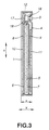
- Fig. 3 is a cross sectional view sowing the structure of a non-aqueous electrolyte secondary battery according to the present invention;
- Fig. 4 is a perspective view showing a state in which an electrode device is inserted into a battery can of the non-aqueous electrolyte secondary battery according to the present invention:
- Fig. 5 is a top view showing a state in which the electrode device has been inserted into the battery can of the non-aqueous electrolyte secondary battery according to the present invention;
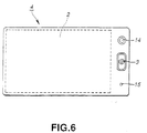
- Fig. 6 is a top view showing the structure of a battery cover of the non-aqueous electrolyte secondary battery according to the present invention;
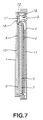
- Fig. 7 is a cross sectional view showing the structure of another embodiment of the non-aqueous electrolyte secondary battery according to the present invention; and
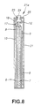
- Fig. 8 is a cross sectional view showing the structure of the non-aqueous electrolyte secondary battery incorporating the battery can, the minimum opening of which is hermetically sealed by the battery cover.
-
- Embodiments of a non-aqueous electrolyte secondary battery according to the present invention will now be described with reference to the drawings.
- As shown in Figs. 3 to 5, the non-aqueous electrolyte secondary battery according to the present invention incorporates an
electrode device 2 accommodated through alargest opening 1a of a battery can 1 formed into a flat and rectangular shape. Thelargest opening 1a is hermetically sealed by abattery cover 4 which incorporates aterminal 3. - The
electrode device 2 incorporates apositive electrode 5 and anegative electrode 6 formed into rectangular shapes and laminated through aseparator 7. Acollecting plate 8 and apressing plate 9 are disposed at two ends of theelectrode device 2. A device-bonding tape 10 is used to secure the end portion of theelectrode device 2. As shown in Fig. 4, theelectrode device 2 is inserted into the battery can 1 through thelargest opening 1a of the battery can 1 in a direction indicated by an arrow X. Theelectrode device 2, a device-pressingplate 11 and aninsulating plate 12 are collectively inserted into the battery can 1. - The
electrode device 2 may be either of a laminated electrode device formed by laminating a plurality of combinations of plate-like positive and negative electrodes or a coil-type electrode device formed by turning elongated positive and negative electrodes. - As shown in Fig. 6, the
battery cover 4 is provided with theterminal 3, asplit valve 14 and an electrolyte injecting opening 15 disposed on a surface of thebattery cover 4 opposite to theelectrode device 2. - The
terminal 3 is joined to thebattery cover 4 through aninsulating portion 16. An end of theterminal 3 is electrically connected to thepositive electrode 5 in the battery can 1 through a positive-electrode lead 17. Another end of theterminal 3 is electrically connected to an external connecting terminal so that a positive terminal is formed. On the other hand, a negative-electrode lead 18 drawn out from thenegative electrode 6 is electrically connected to the battery can 1 through thecollecting plate 8. Thus, the battery can 1 has a polarity which is different from that of theterminal 3. The positive-electrode lead 17 and the negative-electrode lead 18 are drawn out in direction Y in which theelectrode device 2 is laminated, that is, substantially in parallel with thebattery cover 4. Then, the positive-electrode lead 17 and the negative-electrode lead 18 are connected by welding or the like in parallel with the connecting surface of theterminal 3 or the battery can 1. - The
split valve 14 is constituted by metal foil, such as nickel foil, structured to have a splitting pressure adjusted to a predetermined pressure. If the pressure in the battery can 1 is raised for some reason, thesplit valve 14 is split. Thus, the pressure in the battery can 1 is directly released to the outside of the non-aqueous electrolyte secondary battery. Theelectrolyte injecting opening 15 is an opening through which the electrolyte is injected into the battery can 1. After the battery has been assembled, theelectrolyte injecting opening 15 is welded by resistance welding or the like so as to be sealed. - In addition to the
split valve 14, thebattery cover 4 structured as described above may have a current interrupting mechanism for interrupting an electric current if the pressure in the battery can 1 is raised. A Positive Temperature Coefficient device may be provided which interrupts an electric current because resistance thereof is increased if the temperature is raised. - The
battery cover 4 is joined to thelargest opening 1a of the battery can 1. Thebattery cover 4 may be joined as described above by welding, as shown in Fig. 3. As shown in Fig. 7, the outer end of thebattery cover 4 and the periphery of the opening of theterminal 3 may be caulked. Note that the same elements in Fig. 7 are given the same reference numerals and the same elements are omitted from description. - The battery can 1 may be made of any one of known materials. For example, iron, nickel, stainless steel, aluminum or their alloy may be employed. If corrosion takes place owning to the non-aqueous electrolyte, plating may be performed. The battery can 1 can be manufactured by any one of appropriate methods. For example, a drawing process may be employed such that a nickel-plated steel plate is subjected to an ironing process using a mold.
- The
battery cover 4 may be made of any one of known materials including iron, nickel, stainless steel, aluminum and their alloy. If corrosion takes place owning to the non-aqueous electrolyte, plating may be performed. Thebattery cover 4 can be manufactured by any one of known methods. For example, a nickel-plated steel plate is molded by a pressing work. Then, theterminal 3 is caulked. Thus, thebattery cover 4 having theterminal 3 can be manufactured. It is preferable that thesplit valve 14 is provided for thebattery cover 4 before or after the pressing work or after theterminal 3 has been formed. - As shown in Fig. 4, the
electrode device 2 of the non-aqueous electrolyte secondary battery structured as described above is inserted through thelargest opening 1a of the battery can 1 in a direction indicated by an arrow X. The height from a bottom surface 1b to thebattery cover 4, that is, the height of the battery in the direction X (hereinafter called thickness x of the battery) is very small. Therefore, theelectrode device 2 is not deformed by the contact resistance. As a result, theelectrode device 2 can easily and smoothly be inserted. Moreover, clearance k can be created between the battery can 1 and theelectrode device 2, as shown in Fig. 5. Therefore, theelectrode device 2 can easily and smoothly be inserted into the battery can 1. As described above, thelargest opening 1a of the battery can 1 is hermetically sealed by thebattery cover 4. Therefore, the productivity can be improved. - The non-aqueous electrolyte secondary battery has the
large battery cover 4. Therefore, theterminal 3 can significantly easily be formed. Moreover, the safety unit including thesplit valve 14 can be provided for thebattery cover 4. As a result, the productivity and reliability can be improved. - As described above, the non-aqueous electrolyte secondary battery according to the present invention is structured such that the
largest opening 1a of the battery can 1 is hermetically sealed by thebattery cover 4 having theterminal 3. Therefore, the thickness of the battery can be reduced. - Specifically, it is preferable that the thickness x of the battery is 0.5 mm or greater, more preferably 0.6 mm or greater. If the thickness x of the battery is smaller than 0.5 mm, the strength of the battery decreases.
- It is preferable that the thickness x of the battery is 6 mm or smaller, more preferably 5 mm or smaller. If the thickness x of the battery is greater than 6 mm, the
electrode device 2 is able to have sufficient strength. Therefore, theelectrode device 2 can easily be inserted also through the opening which is the smallest area of the battery can 1. In the foregoing case, the advantage that thelargest opening 1a is provided for the largest surface of the battery can 1 cannot be obtained. - When the structure of the present invention is applied to a lithium secondary battery or a lithium ion secondary battery, the following materials may be employed.
- It is preferable that positive-electrode active materials for making the
positive electrode 5 contain lithium in a sufficiently large quantity. For example, a composite metal oxide may be employed which contains lithium expressed by general formula LiMO2 (where M is at least any one of Co, Ni, Mn, Fe, Al, V and Ti) and transition metal. As an alternative to this, an interlayer compound may be employed which contains lithium. - Negative electrode active materials for making the
negative electrode 6 may be any one of oxides having relatively basic potential, such as iron oxide, ruthenium oxide, molybdenum oxide, tungsten oxide or titanium oxide. As an alternative to this, the negative electrode active materials may be a carbon material permitting doping/dedoping of lithium, lithium alloy and lithium ions. - The carbon material for making the
negative electrode 6 may be any one of the following materials: a conjugate resin, such as a phenol resin, an acrylic resin, a vinyl halide resin, a polyimide resin, a polyamideimide resin, a polyamide resin, polyacetylene or poly (p-phenylene); a cellulose derivative; its derivative; and an arbitrary organic polymer compound. In particular, a carbonaceous material or graphite may be employed which includes a furan resin composed of homopolymers or copolymers of furfuryl alcohol or furfural; or petroleum pitch, which can be prepared by performing carbonating such that the foregoing organic material is, for example, baked. - The electrolyte may be non-aqueous electrolyte having a structure that electrolyte is dissolved in non-aqueous solvent For example the non-aqueous solvent may be any one of the following materials: propylene carbonate, ethylene carbonate, butylene carbonate, diethyl carbonate, dimethyl carbonate, methylethyl carbonate, 1, 2-dimethoxyethane, 1, 2-diethoxymethane, γ-butyrolactone, valerolactone, tetrahydrofuran, 2-methyltetrahydrofuran, 1, 3-dioxolan, 4-methyl-1, 3-dioxolan, sulfolane, methylsulfolane, acetonitrile, propyonitrile and their mixture.
- The electrolyte which can be dissolved in the above-mentioned non-aqueous solvent may be any one of known materials. It is preferable that any one of the following materials is employed: LiPF6, LiClO4, LiAsF6, LiBF4, LiB(C6H5)4, CH3SO3Li, CF3SO3Li, LiN (CF3SO2)3, LiC(CF3SO2)3, LiCl and LiBr. It is preferable that LiPF6 is employed.
- Examples of the present invention will now be described.
- A flat and rectangle secondary battery shown in Fig. 3 is manufactured.
- Initially, the
positive electrode 5 is manufactured as follows. - A positive electrode active substance which is 94.5 parts by weight of lithium cobalt oxide (LiCoO2), 3 parts by weight of ketchen black serving as a conductive material and 2.5 parts by weight of polyvinylidene fluoride are mixed. Then, dimethylformamide serving as a dispersant is added so that a slurry material is prepared. Then the slurry is dried with hot air, the temperature of which is 150°C by using a spray driver (manufactured by Sakamoto) for organic solvent. Thus, substantially complete spherical powder having an average particle size of 100 µ is prepared. The thus-prepared granule mixture is molded into a rectangular shape.
- Then, a collector in the form of an aluminum mesh is interposed between the molded mixtures, and then molding is performed to form a rectangular shape. As a result, an elongated positive electrode having a volume density of 3.1 g/ml and size of 39.5 mm × 31.0 mm is obtained. A positive electrode lead constituted by aluminum foil having a thickness of 10 µm has been connected to the collector by ultrasonic welding. The thickness of the elongated
positive electrode 5 is 0.8 mm. - Then, the
negative electrode 6 is manufactured as follows. - Low-expansion mesophase carbon powder containing fixed carbon by 88.5 % and having a total expansion ratio of 0 % (measured by a dilatometer for use in a heat expansion test for coal) under 250 mesh is processed at 300°C for one hour in an oxidation atmosphere. Thus, carbonaceous powder a having an average particle size of 20 µ is obtained.
- Low-expansion mesophase carbon powder containing fixed carbon by 88.5 % and having a total expansion ratio of 0% (measured by a dilatometer for use in a heat expansion test for coal) under 250 mesh is processed at 300°C for one hour in an oxidation atmosphere. Then, the atmosphere is changed to an inert (nitrogen) gas. In the inert gas atmosphere, the material is baked at 900°C for 3 hours so that a material in the form of coke is obtained which is then pulverized. As a result, carbonaceous powder b having an average particle size of 20 µ is obtained.
- The carbonaceous powder a and the carbonaceous powder b are mixed at a ratio of 70:30. Then, polyvinyl alcohol (having molecular weight of 500) serving as a binder is added. Water is employed as the solvent for a kneading process. Then, a mesh not less than 150 µ nor more than 250 µ is employed to perform granulation and adjust the grain size.
- Then, pressure is applied to the granulated mixture with a copper mesh so as to be molded into a rectangular shape. Then, the mesh-integrated electrode is processed at 1000°C for 3 hours in an atmosphere of an inert gas. As a result, an elongated negative electrode made of a sintered body having a size of 41.5 mm × 32.0 mm is obtained. The volume density of the carbonaceous portion of the
negative electrode 6 was 1.25 g/ml and the true specific gravity was 1.75 g/ml. The thickness of the elongatednegative electrode 6 is 0.35 mm. - The manufactured
positive electrodes 5 and thenegative electrodes 6 are laminated throughseparators 7 in the form of micro-porous polyethylene films each having a thickness of 30 µm. The laminating order is such that thenegative electrode 6, theseparator 7, thepositive electrode 5, theseparator 7 and thenegative electrode 6 are sequentially laminated in this sequential order (that is, two negative electrodes, one positive electrode and two separators are provided). Then, the collectingplate 8 and thepressing plate 9 are disposed at two ends of the obtained laminate. A device-bonding tape 10 having a width of 40 mm is used to secure the ends. Thus, theelectrode device 2 is manufactured. To collect electric currents from thenegative electrode 6, the negative-electrode leads 18 are bundled, and then welded to an end of the collectingplate 8. To collect electric currents from thepositive electrode 5, an end of the positive-electrode lead 17 is welded to theterminal 3 joined to thebattery cover 4. - Then, the
electrode device 2, the device-pressingplate 11 and the insulatingplate 12 are accommodated in a flat and rectangle battery can 1 made of iron subjected to nickel plating. The collectingplate 8 is brought into contact with the battery can 1. The battery can 1 and thebattery cover 4 are secured to each other by laser welding. - Then, non-aqueous electrolyte in which one mole of LiPF6 is dissolved in mixture solvent composed of 50 vol% propylene carbonate and 50 vol% diethylcarbonate is injected through the
electrolyte injecting opening 15. Then, theelectrolyte injecting opening 15 is welded so that gastightness in the battery is realized. - According to Example 1, a flat and rectangular secondary battery is manufactured which has a thickness x (height from the bottom surface of the battery can 1 to the battery cover 4) of 3mm, a height of 48 mm and a width of 34 mm.
- Two
positive electrodes 5 each having a thickness of 0.8 mm are prepared. Threenegative electrodes 6 are prepared which consist of twonegative electrodes 6 each having a thickness of 0.35 mm and arranged to be disposed at the outermost positions and onenegative electrode 6 having a thickness of 0.65 mm. Thepositive electrodes 5 and thenegative electrodes 6 are laminated through fourseparators 7. Thus, theelectrode device 2 is manufactured. - A non-aqueous electrolyte secondary battery according to Example 2 of the present invention is manufactured similarly to Example 1 except for the above-mentioned
electrode device 2. The non-aqueous electrolyte secondary battery according to this example is a flat and rectangular battery having a thickness x of 4.5 mm, a height of 48 mm and a width of 34 mm. Note that the battery can 1 must correspond to the designed thickness. - Three
positive electrodes 5 each having a thickness of 0.8 mm are prepared. Fournegative electrodes 6 are prepared which consist of twonegative electrodes 6 each having a thickness of 0.35 mm and arranged to be disposed at the outermost positions and twonegative electrodes 6 each having a thickness of 0.65 mm. Thepositive electrodes 5 and thenegative electrodes 6 are laminated through sixseparators 7 so that theelectrode device 2 is manufactured. - The non-aqueous electrolyte secondary battery according to Example 3 of the present invention is manufactured similarly to Example 1 except for the above-mentioned
electrode device 2. The non-aqueous electrolyte secondary battery according to this example is a flat and rectangular secondary battery having a thickness x of 6mm, a height of 48 mm and a width of 34 mm. Note that the battery can 1 must correspond to the deigned thickness. - In Example 4 of the present invention, a molded positive electrode having size of 39.5 mm × 30.0 mm is employed to serve as the positive electrode. As the negative electrode, a molded negative electrode having size of 41.5 mm × 31.0 mm is employed. The battery can 1 and the
battery cover 4 are secured to each other by caulking so that a flat and rectangular secondary battery (see Fig. 7) is manufactured. The other structure of the battery according to this example are similar to those of Example 1. The battery can 1 must correspond to the designed thickness. - As shown in Fig. 8, a battery according to Comparative Example 1 is a flat and rectangular secondary battery (see Fig. 7) incorporating a battery can 21 having an
opening 21a formed in the surface having a smallest area thereof. As a battery cover for hermetically sealing theopening 21, a terminal 24 is joined through an insulatingportion 23. The other structures of the battery according to this comparative example are similar to those according to Example 1. - As shown in Fig. 8, a battery according to Comparative Example 2 is a flat and rectangular secondary battery incorporating a battery can which is a battery can 21 having an
opening 21a formed in the surface having a smallest area. Moreover, the battery incorporates abattery cover 25 to which a terminal 24 is joined to hermetically seal theopening 21a through an insulatingportion 23. The other structures of the battery according to this comparative example are similar to those according to Example 2. - As shown in Fig. 8, a battery according to Comparative Example 3 is a flat and rectangular secondary battery incorporating a battery can 21 having an
opening 21a formed in the surface having a smallest area. Moreover, a battery can 25 is employed which hermetically seal theopening 21a and to which a terminal 24 is joined through an insulatingportion 23. The other structures of the battery according to this comparative example are similar to those according to Example 3. - One hundred samples of each of the flat and rectangular secondary batteries according to Examples 1 to 4 and Comparative Examples 1 to 3 were manufactured. Then, whether or not insertion of the electrode device into the battery can was performed easily and smoothly was examined. Results were shown in Table 1.
Result of Insertion of Electrode Device Number of Unsatisfactory Results Ratio of Unsatisfactory Results [%] Example 1 0/100 0 Example 2 0/100 0 Example 3 0/100 0 Example 4 0/100 0 Comparative Example 1 17/100 17.0 Comparative Example 2 8/100 8.0 Comparative Example 3 3/100 3.0 - As can be understood from Table 1, the flat and rectangular secondary batteries according to Example 1 to 4 and having the structure that the
largest opening 1a of the battery can 1 is hermetically sealed by thebattery cover 4 having theterminal 3 enables theelectrode device 2 to easily be inserted into the battery can 1 even if the thickness x of the battery is reduced. The insertion of theelectrode device 2 can satisfactorily be performed. Thus, batteries exhibiting excellent productivity can be obtained. - On the other hand, the flat and rectangular secondary batteries according to Comparative Examples 1 to 3 and having the structure that the
minimum opening 21a of the battery can 21 is hermetically sealed by thebattery cover 25 having the terminal 24 results in difficulty in inserting theelectrode device 2 into the battery can 21 when the thickness x of the battery is reduced. That is, insertion of the electrode device cannot easily and smoothly be performed. - As described above, according to the present invention, the largest opening of the battery can is hermetically sealed by the battery cover having the terminal. Therefore, even if the thickness of the battery is reduced, the electrode device can easily be inserted into the battery can. Since a large battery cover can be provided, the terminal can easily be formed. Moreover, the safety unit including the split valve can easily be disposed. As a result, a non-aqueous electrolyte secondary battery exhibiting excellent productivity and reliability and having a high energy density can be provided.
- Although the invention has been described in its preferred form with a certain degree of particularity, it is understood that the present disclosure of the preferred form can be changed in the details of construction and in the combination and arrangement of parts without departing from the spirit and the scope of the invention as hereinafter claimed.
Claims (8)
- A non-aqueous electrolyte secondary battery comprising:a battery can which accommodates an electrode device and non-aqueous electrolyte, whereina largest opening of said battery can is hermetically sealed by a battery cover incorporating a terminal.
- A non-aqueous electrolyte secondary battery according to claim 1,
wherein said battery cover has a safety unit which outwards releases internal pressure of said battery when the internal pressure in said battery has been raised to a predetermined pressure. - A non-aqueous electrolyte secondary battery according to claim 2,
wherein said safety unit incorporates at least a member, which is selected from a group consisting of a current interrupting unit and a Positive Temperature Coefficient device, and a split valve. - A non-aqueous electrolyte secondary battery according to claim 1,
wherein said battery cover has an electrolyte injecting opening through which the electrolyte is injected. - A non-aqueous electrolyte secondary battery according to claim 1,
wherein said electrode device is formed into a laminate constituted by laminating a positive electrode and a negative electrode substantially in parallel with said battery cover through a separator. - A non-aqueous electrolyte secondary battery according to claim 1,
wherein leads drawn out from said electrode device and laid substantially in parallel with said battery cover are connected to said terminal. - A non-aqueous electrolyte secondary battery according to claim 1,
wherein said battery can is formed into a rectangular shape. - A non-aqueous electrolyte secondary battery according to claim 1,
wherein the height of said battery can from a bottom surface thereof to said battery cover is 0.5 mm to 6 mm.
Applications Claiming Priority (2)
| Application Number | Priority Date | Filing Date | Title |
|---|---|---|---|
| JP35173997 | 1997-12-19 | ||
| JP35173997A JP3885327B2 (en) | 1997-12-19 | 1997-12-19 | Flat rectangular non-aqueous electrolyte secondary battery |
Publications (2)
| Publication Number | Publication Date |
|---|---|
| EP0924779A1 true EP0924779A1 (en) | 1999-06-23 |
| EP0924779B1 EP0924779B1 (en) | 2005-03-30 |
Family
ID=18419281
Family Applications (1)
| Application Number | Title | Priority Date | Filing Date |
|---|---|---|---|
| EP98124035A Expired - Lifetime EP0924779B1 (en) | 1997-12-19 | 1998-12-17 | Non-aqueous electrolyte secondary battery |
Country Status (4)
| Country | Link |
|---|---|
| US (1) | US6572998B2 (en) |
| EP (1) | EP0924779B1 (en) |
| JP (1) | JP3885327B2 (en) |
| DE (1) | DE69829544T2 (en) |
Cited By (4)
| Publication number | Priority date | Publication date | Assignee | Title |
|---|---|---|---|---|
| EP2040322A2 (en) | 2007-09-24 | 2009-03-25 | Greatbatch Ltd. | Electrochemical cell with tightly held electrode assembly |
| WO2011012208A1 (en) * | 2009-07-31 | 2011-02-03 | Daimler Ag | Galvanic cell having overpressure protection |
| WO2016120359A1 (en) * | 2015-01-30 | 2016-08-04 | Robert Bosch Gmbh | Battery cell and battery system |
| FR3109026A1 (en) * | 2020-04-07 | 2021-10-08 | Saft | Electrochemical element for battery and corresponding battery |
Families Citing this family (20)
| Publication number | Priority date | Publication date | Assignee | Title |
|---|---|---|---|---|
| JP2001057179A (en) * | 1999-08-18 | 2001-02-27 | Sony Corp | Secondary battery and its case |
| AU1990301A (en) * | 1999-12-22 | 2001-07-03 | Shenzhen Lb Battery Co., Ltd | A thin battery |
| JP2002203775A (en) * | 2000-12-28 | 2002-07-19 | Nikon Corp | Exposure equipment |
| JP2003142043A (en) | 2001-07-09 | 2003-05-16 | Hitachi Maxell Ltd | Battery |
| KR20040048295A (en) | 2002-12-02 | 2004-06-07 | 히다치 막셀 가부시키가이샤 | Battery |
| KR100958647B1 (en) * | 2002-12-18 | 2010-05-20 | 삼성에스디아이 주식회사 | Pouch Type Secondary Battery Unit |
| JP5040056B2 (en) * | 2004-02-17 | 2012-10-03 | パナソニック株式会社 | Oval battery |
| KR20110049847A (en) * | 2008-09-09 | 2011-05-12 | 파나소닉 주식회사 | Nonaqueous Electrolyte Secondary Battery and Manufacturing Method Thereof |
| JP4835742B2 (en) * | 2009-02-20 | 2011-12-14 | ソニー株式会社 | Battery and battery pack |
| KR100919691B1 (en) * | 2009-06-24 | 2009-10-06 | 에너테크인터내셔널 주식회사 | Unit cell for a secondary battery having a conductive sheet layer and a lithium ion secondary battery using the same |
| DE102011105040A1 (en) | 2011-05-06 | 2012-11-08 | Klaus Ebert | Lithiumsenkundärzellenanordnung |
| TWI431837B (en) | 2011-06-27 | 2014-03-21 | Delta Electronics Inc | Energy storage device package |
| KR101441524B1 (en) | 2012-02-07 | 2014-09-17 | 주식회사 엘지화학 | Secondary Battery of Novel Structure |
| KR101432224B1 (en) * | 2012-02-07 | 2014-08-26 | 주식회사 엘지화학 | Secondary Battery Pack of Embedded Type of Novel Structure |
| JP6031832B2 (en) * | 2012-05-31 | 2016-11-24 | 株式会社豊田自動織機 | Power storage device |
| KR101596269B1 (en) * | 2013-02-13 | 2016-02-23 | 주식회사 엘지화학 | Battery Cell of Novel Structure |
| JP2015153682A (en) * | 2014-02-18 | 2015-08-24 | 日立マクセル株式会社 | Nonaqueous electrolyte secondary battery |
| JP6284248B1 (en) * | 2016-11-22 | 2018-02-28 | セイコーインスツル株式会社 | Electrochemical cell and method for producing electrochemical cell |
| JP7117157B2 (en) * | 2018-06-01 | 2022-08-12 | 日産自動車株式会社 | battery device |
| WO2021065334A1 (en) * | 2019-09-30 | 2021-04-08 | 株式会社村田製作所 | Secondary battery |
Citations (11)
| Publication number | Priority date | Publication date | Assignee | Title |
|---|---|---|---|---|
| US4182028A (en) * | 1976-08-02 | 1980-01-08 | Gte Laboratories Inc. | Hermetically sealed button-type electrochemical cell and method for making same |
| EP0081339A2 (en) * | 1981-12-04 | 1983-06-15 | Venture Technology Limited | Sealing of electrochemical cells |
| JPS61285655A (en) * | 1985-06-12 | 1986-12-16 | Hitachi Maxell Ltd | Manufacture of thin enclosed cell |
| EP0225679A1 (en) * | 1985-11-04 | 1987-06-16 | Eveready Battery Company, Inc. | Electrochemical cell |
| JPH01163960A (en) * | 1987-12-21 | 1989-06-28 | Shin Kobe Electric Mach Co Ltd | Flat type battery and its manufacture |
| JPH0757722A (en) * | 1993-08-19 | 1995-03-03 | Ricoh Co Ltd | Thin type battery |
| JPH0831402A (en) * | 1994-07-13 | 1996-02-02 | A T Battery:Kk | Sealed electrode terminal structure |
| JPH0935748A (en) * | 1995-07-24 | 1997-02-07 | Ricoh Co Ltd | Secondary battery |
| JPH09213286A (en) * | 1996-01-30 | 1997-08-15 | Ricoh Co Ltd | Thin lithium battery and method of manufacturing the battery |
| EP0810677A1 (en) * | 1995-12-19 | 1997-12-03 | Matsushita Electric Industrial Co., Ltd. | Thin battery |
| JPH09320550A (en) * | 1996-05-28 | 1997-12-12 | Yuasa Corp | Battery |
Family Cites Families (2)
| Publication number | Priority date | Publication date | Assignee | Title |
|---|---|---|---|---|
| JP3222022B2 (en) * | 1994-10-27 | 2001-10-22 | シャープ株式会社 | Method for producing lithium secondary battery and negative electrode active material |
| US5783326A (en) * | 1996-03-14 | 1998-07-21 | Kabushiki Kaisha Toshiba | Nonaqueous electrolyte secondary battery |
-
1997
- 1997-12-19 JP JP35173997A patent/JP3885327B2/en not_active Expired - Fee Related
-
1998
- 1998-12-17 EP EP98124035A patent/EP0924779B1/en not_active Expired - Lifetime
- 1998-12-17 DE DE69829544T patent/DE69829544T2/en not_active Expired - Fee Related
- 1998-12-17 US US09/215,743 patent/US6572998B2/en not_active Expired - Fee Related
Patent Citations (11)
| Publication number | Priority date | Publication date | Assignee | Title |
|---|---|---|---|---|
| US4182028A (en) * | 1976-08-02 | 1980-01-08 | Gte Laboratories Inc. | Hermetically sealed button-type electrochemical cell and method for making same |
| EP0081339A2 (en) * | 1981-12-04 | 1983-06-15 | Venture Technology Limited | Sealing of electrochemical cells |
| JPS61285655A (en) * | 1985-06-12 | 1986-12-16 | Hitachi Maxell Ltd | Manufacture of thin enclosed cell |
| EP0225679A1 (en) * | 1985-11-04 | 1987-06-16 | Eveready Battery Company, Inc. | Electrochemical cell |
| JPH01163960A (en) * | 1987-12-21 | 1989-06-28 | Shin Kobe Electric Mach Co Ltd | Flat type battery and its manufacture |
| JPH0757722A (en) * | 1993-08-19 | 1995-03-03 | Ricoh Co Ltd | Thin type battery |
| JPH0831402A (en) * | 1994-07-13 | 1996-02-02 | A T Battery:Kk | Sealed electrode terminal structure |
| JPH0935748A (en) * | 1995-07-24 | 1997-02-07 | Ricoh Co Ltd | Secondary battery |
| EP0810677A1 (en) * | 1995-12-19 | 1997-12-03 | Matsushita Electric Industrial Co., Ltd. | Thin battery |
| JPH09213286A (en) * | 1996-01-30 | 1997-08-15 | Ricoh Co Ltd | Thin lithium battery and method of manufacturing the battery |
| JPH09320550A (en) * | 1996-05-28 | 1997-12-12 | Yuasa Corp | Battery |
Non-Patent Citations (7)
| Title |
|---|
| PATENT ABSTRACTS OF JAPAN vol. 011, no. 148 (E - 506) 14 May 1987 (1987-05-14) * |
| PATENT ABSTRACTS OF JAPAN vol. 013, no. 435 (E - 825) 28 September 1989 (1989-09-28) * |
| PATENT ABSTRACTS OF JAPAN vol. 095, no. 006 31 July 1995 (1995-07-31) * |
| PATENT ABSTRACTS OF JAPAN vol. 096, no. 006 28 June 1996 (1996-06-28) * |
| PATENT ABSTRACTS OF JAPAN vol. 097, no. 006 30 June 1997 (1997-06-30) * |
| PATENT ABSTRACTS OF JAPAN vol. 097, no. 012 25 December 1997 (1997-12-25) * |
| PATENT ABSTRACTS OF JAPAN vol. 098, no. 004 31 March 1998 (1998-03-31) * |
Cited By (8)
| Publication number | Priority date | Publication date | Assignee | Title |
|---|---|---|---|---|
| EP2040322A2 (en) | 2007-09-24 | 2009-03-25 | Greatbatch Ltd. | Electrochemical cell with tightly held electrode assembly |
| US20090081552A1 (en) * | 2007-09-24 | 2009-03-26 | Greatbatch Ltd. | Electrochemical cell with tightly held electrode assembly |
| EP2040322A3 (en) * | 2007-09-24 | 2009-06-10 | Greatbatch Ltd. | Electrochemical cell with tightly held electrode assembly |
| WO2011012208A1 (en) * | 2009-07-31 | 2011-02-03 | Daimler Ag | Galvanic cell having overpressure protection |
| WO2016120359A1 (en) * | 2015-01-30 | 2016-08-04 | Robert Bosch Gmbh | Battery cell and battery system |
| US10461305B2 (en) | 2015-01-30 | 2019-10-29 | Robert Bosch Gmbh | Battery cell and battery system |
| FR3109026A1 (en) * | 2020-04-07 | 2021-10-08 | Saft | Electrochemical element for battery and corresponding battery |
| WO2021204842A1 (en) * | 2020-04-07 | 2021-10-14 | Saft | Electrochemical element for a battery and corresponding battery |
Also Published As
| Publication number | Publication date |
|---|---|
| JPH11185820A (en) | 1999-07-09 |
| DE69829544D1 (en) | 2005-05-04 |
| US6572998B2 (en) | 2003-06-03 |
| EP0924779B1 (en) | 2005-03-30 |
| US20010006746A1 (en) | 2001-07-05 |
| DE69829544T2 (en) | 2006-03-30 |
| JP3885327B2 (en) | 2007-02-21 |
Similar Documents
| Publication | Publication Date | Title |
|---|---|---|
| US6572998B2 (en) | Non-aqueous electrolyte secondary battery | |
| JP3866740B2 (en) | Non-aqueous electrolyte secondary battery, assembled battery and battery pack | |
| EP1128450B1 (en) | Electrode connection for battery and methods of producing the same | |
| US20170092922A1 (en) | Non-aqueous electrolyte battery | |
| US6869723B2 (en) | Nonaqueous-electrolyte secondary battery | |
| EP0838098B1 (en) | Nonaqueous electrolyte secondary battery | |
| EP0627780B1 (en) | Non-aqueous liquid electrolyte secondary cell | |
| US20010024757A1 (en) | Organic electrolytic soultion and lithium secondary battery adopting the same | |
| EP3270445B1 (en) | Nonaqueous electrolyte battery and battery pack | |
| JP2001167767A (en) | Non-aqueous electrolyte secondary battery | |
| US8822070B2 (en) | Battery with secure short-circuiting mechanism | |
| EP3322024A1 (en) | Nonaqueous electrolyte battery and battery pack | |
| KR20230054601A (en) | Lithium secondary battery | |
| JP6813332B2 (en) | Electrodes, electrode bodies, secondary batteries, battery modules and vehicles | |
| US7585591B2 (en) | Battery including rolled electrodes and straight lead terminals | |
| JPH10208777A (en) | Non-aqueous electrolyte secondary battery | |
| EP0936690A2 (en) | Nonaqueous electrolyte battery having wound electrode structures | |
| US20220077503A1 (en) | Non-aqueous electrolyte secondary battery and method for manufacturing same | |
| US6686087B2 (en) | Non-aqueous electrolyte secondary cell with a spirally wound electrode unit | |
| KR102673253B1 (en) | Lithium secondary battery | |
| JP2002117903A (en) | Non-aqueous electrolyte battery | |
| US7172836B2 (en) | Nonaqueous electrolyte battery and method for manufacturing it, and positive active material, and method for producing it | |
| JPH10247522A (en) | Non-aqueous electrolyte secondary battery | |
| EP4611086A1 (en) | Electrode for rechargeable battery and electrode assembly | |
| JPH0992257A (en) | Non-aqueous electrolyte secondary battery |
Legal Events
| Date | Code | Title | Description |
|---|---|---|---|
| PUAI | Public reference made under article 153(3) epc to a published international application that has entered the european phase |
Free format text: ORIGINAL CODE: 0009012 |
|
| AK | Designated contracting states |
Kind code of ref document: A1 Designated state(s): DE FR GB |
|
| AX | Request for extension of the european patent |
Free format text: AL;LT;LV;MK;RO;SI |
|
| 17P | Request for examination filed |
Effective date: 19991125 |
|
| AKX | Designation fees paid |
Free format text: DE FR GB |
|
| 17Q | First examination report despatched |
Effective date: 20001116 |
|
| GRAP | Despatch of communication of intention to grant a patent |
Free format text: ORIGINAL CODE: EPIDOSNIGR1 |
|
| GRAS | Grant fee paid |
Free format text: ORIGINAL CODE: EPIDOSNIGR3 |
|
| GRAA | (expected) grant |
Free format text: ORIGINAL CODE: 0009210 |
|
| AK | Designated contracting states |
Kind code of ref document: B1 Designated state(s): DE FR GB |
|
| REG | Reference to a national code |
Ref country code: GB Ref legal event code: FG4D |
|
| REF | Corresponds to: |
Ref document number: 69829544 Country of ref document: DE Date of ref document: 20050504 Kind code of ref document: P |
|
| PLBE | No opposition filed within time limit |
Free format text: ORIGINAL CODE: 0009261 |
|
| STAA | Information on the status of an ep patent application or granted ep patent |
Free format text: STATUS: NO OPPOSITION FILED WITHIN TIME LIMIT |
|
| ET | Fr: translation filed | ||
| 26N | No opposition filed |
Effective date: 20060102 |
|
| PGFP | Annual fee paid to national office [announced via postgrant information from national office to epo] |
Ref country code: FR Payment date: 20081212 Year of fee payment: 11 |
|
| PGFP | Annual fee paid to national office [announced via postgrant information from national office to epo] |
Ref country code: DE Payment date: 20081211 Year of fee payment: 11 |
|
| PGFP | Annual fee paid to national office [announced via postgrant information from national office to epo] |
Ref country code: GB Payment date: 20081217 Year of fee payment: 11 |
|
| GBPC | Gb: european patent ceased through non-payment of renewal fee |
Effective date: 20091217 |
|
| REG | Reference to a national code |
Ref country code: FR Ref legal event code: ST Effective date: 20100831 |
|
| PG25 | Lapsed in a contracting state [announced via postgrant information from national office to epo] |
Ref country code: FR Free format text: LAPSE BECAUSE OF NON-PAYMENT OF DUE FEES Effective date: 20091231 |
|
| PG25 | Lapsed in a contracting state [announced via postgrant information from national office to epo] |
Ref country code: DE Free format text: LAPSE BECAUSE OF NON-PAYMENT OF DUE FEES Effective date: 20100701 |
|
| PG25 | Lapsed in a contracting state [announced via postgrant information from national office to epo] |
Ref country code: GB Free format text: LAPSE BECAUSE OF NON-PAYMENT OF DUE FEES Effective date: 20091217 |