EP0924660B1 - Coin mechanism - Google Patents
Coin mechanism Download PDFInfo
- Publication number
- EP0924660B1 EP0924660B1 EP98309877A EP98309877A EP0924660B1 EP 0924660 B1 EP0924660 B1 EP 0924660B1 EP 98309877 A EP98309877 A EP 98309877A EP 98309877 A EP98309877 A EP 98309877A EP 0924660 B1 EP0924660 B1 EP 0924660B1
- Authority
- EP
- European Patent Office
- Prior art keywords
- coin
- cashbox
- coins
- cassette
- tubes
- Prior art date
- Legal status (The legal status is an assumption and is not a legal conclusion. Google has not performed a legal analysis and makes no representation as to the accuracy of the status listed.)
- Expired - Lifetime
Links
- 230000007246 mechanism Effects 0.000 title claims description 38
- 230000008859 change Effects 0.000 claims description 17
- 238000012360 testing method Methods 0.000 description 12
- 230000015654 memory Effects 0.000 description 6
- 238000001514 detection method Methods 0.000 description 3
- 230000004044 response Effects 0.000 description 3
- 238000012550 audit Methods 0.000 description 2
- 230000004075 alteration Effects 0.000 description 1
- 238000013461 design Methods 0.000 description 1
- 238000010586 diagram Methods 0.000 description 1
- 230000008030 elimination Effects 0.000 description 1
- 238000003379 elimination reaction Methods 0.000 description 1
- 230000005484 gravity Effects 0.000 description 1
- 238000003780 insertion Methods 0.000 description 1
- 230000037431 insertion Effects 0.000 description 1
- 239000000463 material Substances 0.000 description 1
- 238000000034 method Methods 0.000 description 1
- 238000012986 modification Methods 0.000 description 1
- 230000004048 modification Effects 0.000 description 1
- 239000002991 molded plastic Substances 0.000 description 1
- 238000012545 processing Methods 0.000 description 1
- 230000000717 retained effect Effects 0.000 description 1
- 230000032258 transport Effects 0.000 description 1
Images



Classifications
-
- G—PHYSICS
- G07—CHECKING-DEVICES
- G07F—COIN-FREED OR LIKE APPARATUS
- G07F9/00—Details other than those peculiar to special kinds or types of apparatus
- G07F9/06—Coin boxes
-
- G—PHYSICS
- G07—CHECKING-DEVICES
- G07D—HANDLING OF COINS OR VALUABLE PAPERS, e.g. TESTING, SORTING BY DENOMINATIONS, COUNTING, DISPENSING, CHANGING OR DEPOSITING
- G07D1/00—Coin dispensers
- G07D1/02—Coin dispensers giving change
Definitions
- the invention relates to coin mechanisms, especially for use in vending machines and the like.
- a coin mechanism for receiving and testing the acceptability of inserted coins.
- Acceptable coins are diverted either to one of a plurality of coin storage tubes, each for storing and dispensing in change coins of a respective denomination, or, if no coin tube is provided for a particular denomination because that denomination is not needed for change, or if the relevant tube is full, to a separate cashbox.
- the cashbox is situated remote from the coin mechanism, within the vending machine, but connected to it by a passageway.
- Coins are collected periodically from the cashbox by a serviceman.
- the coin storage tubes may be arranged within a cassette which is removable from and replaceable in the coin testing mechanism, as described, for example, in GB-A-2 246 897 .
- DE 41 21 985 A1 discloses a coin-operated games machine containing a symbol game device, a coin tester followed by individual coin collection containers, a banknote tester, a banknote collection container and a central controller.
- One coin collection container is a hopper with a coin output device controlled via the control unit by the banknote tester.
- the banknote tester can be selected via key control to operate as a banknote changer using the hopper or to activate the symbol game device
- US 5,056,643 discloses an arrangement including several cashier vending-type machines for goods and services.
- Each machine in addition to having at least one cash box, also has not only several replaceable and preferably self-filling coin-storing units for returning or refunding money, but also has a computer that controls the machine, produces a balance, and is provided with a random access memory that is protected against the loss of power.
- each coin-storing unit is provided with an electronic memory that is protected against loss of data and that, upon insertion of that unit into a machine, stores a coding that identifies the machine.
- US 5,400,891 discloses a coin testing mechanism of the kind provided with a removable and replaceable cassette is described.
- the coin testing mechanism includes a plurality of coin storage tubes and means for dispensing coins from the storage tubes, and the removable cassette is an assembly which comprises a plurality of storage tube modules.
- Each of the modules comprises at least one storage tube, and the modules are retained in the assembly by releasable and reusable retaining means to enable exchanging one module of the cassette for another.
- EP 0 355 238 A1 discloses an assembly of a plurality of automatic product or service vending machines, for example travel ticket dispensers within a particular fare zone or ticket dispensers for a car-park company, each machine possessing, in addition to at least one cash box, a plurality of exchangeable, preferably self-replenishing coin stores for issuing change and a computer which controls the machine and produces a balance, and has write/read memories which are protected against power supply failure.
- each coin store is provided with an electronic memory which is protected against data loss and in which, each time the coin store is inserted in a machine, the code identifying this machine, for example the machine number, is stored.
- US 4,374,557 discloses a coin changer comprises a coin changer main part and an electronic type coin discrimination device which can be readily mounted to and detached from the coin changer main part.
- the electronic type coin discrimination device includes a detection coil for detecting characteristics of a deposited coin, a discrimination circuit for judging whether the deposited coin is a true coin or a counterfeit one in response to the output of the detection coil and produces a sole kind of discrimination signal representative of trueness or falsity of the coin regardless of the denomination of the coin, a true coin passage and a counterfeit coin passage provided behind the detection coil and a mechanical coin sort-out device provided in the true coin passage for sorting out coins by denomination.
- the coin changer main part comprises coin switches for detecting coins of respective denominations having been sorted out by the sort-out device, a coin receiving device for receiving the coins which have passed through the coin switches, a control circuit for effecting control operations including a money amount counting control, a vend control and a change payout control, and an electromagnetic device for distributing the deposited coin to either the true coin passage or the counterfeit coin passage in the coin discrimination device in response to the output of the discrimination circuit.
- This electromagnetic device distributes the coins by projecting or withdrawing a reject pin into or from a bifurcation of the true coin passage and the counterfeit coin passage.
- US 5,082,100 discloses a device comprising a housing with a front face provided with an admission slot for coins and with a coin return receptacle.
- a conveyor situated in a shaft communicating by gravity with the return receptacle, transports the coins from the admission slot to a processing module.
- EP 0 351 295 A1 discloses another coin mechanism for ticket machines.
- Each coin tube has a code carrier.
- output devices having storage means are provided for storing the value of coins contained in a coin tube.
- the present invention provides a coin mechanism as defined in claim 1, and a vending machine comprising such a coin mechanism.
- Fig. 1 shows a coin mechanism, indicated generally by the reference numeral 1, for use in a vending machine (not shown).
- the coin mechanism includes a mainframe 2 supporting a coin validator 4 for testing the validity of coins inserted through a coin inlet 6 and a coin separator 8 for routing the inserted coins according to the outcome of the validity test.
- the coin separator is connected to a coin storage section, indicated generally by the reference numeral 10, and to a coin reject passageway 12 extending along the front left hand corner of the coin storage section.
- a coin dispensing section 14 for dispensing coins as change from the coin storage section.
- a coin return tray 16 is arranged below the coin mechanism 1 for receiving coins from the reject passageway 12 or coins dispensed from the coin storage section 10, to be collected, for example, by a customer.
- the circuit of the present embodiment of the invention incorporates a microprocessor 18 connected to data and address buses 20 and 22. Although separate buses are shown, data and address signals could instead be multiplexed on a single bus. A bus for control signals could also be provided.
- the microprocessor 18 is connected via the buses 20 and 22 to a read-only memory (ROM) 24 and a random access memory (RAM) 26.
- ROM read-only memory
- RAM random access memory
- the ROM 24 stores the program controlling the overall operation of the microprocessor 18, and the RAM 26 is used by the microprocessor 18 as a scratch-pad memory.
- the microprocessor 18, the ROM 24 and the RAM 26 are, in the preferred embodiment, combined on a single integrated circuit.
- the microprocessor 18 may also be connected via the buses 20 and 22 to an EAROM (Electrically Alterable Read Only Memory) 28 for storing a variety of alterable parameters.
- EAROM Electrically Alterable Read Only Memory
- the microprocessor 18 is also coupled via the buses 20 and 22 to input/output circuitry indicated at 30.
- the circuitry 30 includes user-operable switches, circuits for operating the dispenser 16 and the gates of the coin separator 8, the circuitry of the coin validator 4, and a display visible to a user of the apparatus for displaying an accumulated credit value and an indication when insufficient coins are stored to guarantee that change will be available.
- the input/output circuitry 30 also includes an interface between the control circuit of the apparatus and a vending machine 32 to which it is connected, and a further interface to an audit device 34.
- the microprocessor 18 In operation of the apparatus the microprocessor 18 successively tests the signals from the validator to determine whether a coin has been inserted in the apparatus. When a credit has been accumulated, the microprocessor also tests signals from the vending machine to determine whether a vending operation has been carried out. In response to various signals received by the microprocessor 18, various parts of the program stored in the ROM 24 are carried out.
- the microprocessor is thus arranged to control the gates in the separator 8 in order to deliver the coins to the required locations, and is also operable to cause appropriate information to be shown on the displays of the apparatus and to deliver signals to the vending machine to permit or prevent vending operations.
- the microprocessor is also operable to control the dispenser to deliver appropriate amounts of change.
- the audit device 34 maintains a record of the number of coins of each denomination received and dispensed by the apparatus.
- the coin storage section 10 comprises two coin storage tubes 36, 38 and a cashbox 40, as shown in outline in Fig. 1 .
- the coin storage tubes 36, 38 are arranged side by side in the right half of the coin storage section 10 and extend between the coin separator 8 and the coin dispensing section 14, and are open at both ends. Coins enter the coin storage tubes 36, 38 at one end from the coin separator 8, are stored within the tubes in a stack face to face and are dispensed from the tubes at the other end. Associated with each coin storage tube are pairs of coin level sensors (not shown) for detecting when the stack of coins within a tube exceeds a first, higher, level or is below a second, lower, level.
- the cashbox 40 is arranged in the left half of the coin storage section 10, partially behind the reject passageway 12, and it extends between the coin separator 8 and the coin dispensing section 14.
- the cashbox 40 has four walls, a base, and is open at the top, to receive coins from the separator 8.
- the width of the cashbox 40 is approximately twice that of each of the coin storage tubes 36, 38.
- the base of the cashbox 40 is inclined downwardly towards the front, as shown in Fig. 3 .
- At the lower end of the front wall of the cashbox there is a slidable door 42, which is behind and approximately the same width as the reject passageway 12.
- the door 42 is slidable up and down using a handle 44 which extends through and is movable within a slot 46 in the front wall of the coin storage section 10 next to the reject passageway 12.
- a handle 44 which extends through and is movable within a slot 46 in the front wall of the coin storage section 10 next to the reject passageway 12.
- the cashbox 40 and the coin storage tubes 36, 38 are made of moulded plastics material.
- the coin dispensing section 14 comprises two dispensers, each arranged underneath a respective coin storage tube 36, 38.
- the coin mechanism 1 is configured to determine which denominations of coins are acceptable, and of those acceptable denominations, which denominations are to be directed to the cashbox 40 and which denominations to the coin storage tubes 36, 38 to be used for change.
- the coin mechanism accepts 5p, 10p, 20p, 50p and £1 coins. 5p coins are to be stored in the first coin storage tube 36, 10p coins are to be stored in the second coin storage tube 38 and the other acceptable denominations are to be stored in the cashbox 40.
- a coin inserted into the coin inlet 6 rolls into the validator 4 and is subjected there to various tests to determine if it is a coin of a denomination deemed acceptable by the mechanism, in accordance with known techniques. If the coin is an acceptable coin it is directed by a gate within the coin validator 4 to the coin separator 8 which includes gates which are operated according to the outcome of the tests in the validator to determine the subsequent path of the coin, as is known. If the coin is not an acceptable coin, it is directed by the gate within the coin validator 4 to the coin reject passageway 12, which leads outside the coin storage section 10 and the dispensing section 14 to the coin return tray 16.
- the separator 8 directs the coin to the relevant tube. If the relevant tube is full, or if the coin is one of the other acceptable denominations, then the separator 8 directs the coin along a path (or one of a plurality of paths) that leads to the cashbox 40. In a known manner, when a coin of a given denomination is needed for change, the dispensers 14 remove a single coin from the bottom of the stack of coins within the tube 36, 38 and then release the coin so it drops through a hole in the base of the dispensing section 14 into the coin return tray 16.
- coins accumulate within the cashbox 40, because coins are not dispensed as change from it.
- the coins in the cashbox are not stored in an ordered manner, such as a stack as in the coin tubes, but in a disordered fashion.
- a serviceman visits the mechanism to empty the cashbox 40. This is done by moving the handle 44 upwards, which causes the door 42 of the cashbox 40 to open. Because the base of the cashbox 40 is inclined downwardly towards the door 42, coins slide from the cashbox into the reject passageway 12 and thence to the coin return tray 16. The coins are collected from the coin return tray 16.
- the cashbox 40a is arranged in the right side of the coin storage section 10, away from the coin reject passageway 12.
- the two coin tubes 36, 38 with their associated dispensers are arranged in the left side of the coin storage section 10.
- the base of the cashbox 40a is in the form of a slidable tray 47, which extends through the front of the coin storage section 10 so that one end can be grasped from outside to move it.
- chutes may be arranged below the cashbox 40a, which connect to the reject route 12, so that coins emptied from the cashbox 40a, when the base of the cashbox is open, are directed to the reject route, or to any other suitable path to allow the coins to be collected.
- At least part of the front of the housing in the coin storage section may be removable, or provided with a door, so that at least part of the cashbox is exposed.
- the cashbox may have a hinged door on its front wall allowing the coins in the cashbox to be removed.
- all of the front of the housing in the coin storage section may be removable, to expose the cashbox and the coin storage tubes.
- the cashbox may be so mounted that it can be removed from the housing and can be emptied simply by turning it upside down.
- the storage tubes are also removably mounted, the cashbox can be replaced with a different cashbox, for example, one of a different shape and size.
- the cashbox in the example given above could be replaced with a larger cashbox, occupying space equivalent to that of three coin storage tubes, and with one coin storage tube provided for change instead of two.
- a cashbox may take up all the space within the coin storage area, with no coin storage tubes provided. If the stores within the coin mechanism are changed, corresponding alterations to the routing and dispensing of coins may be necessary.
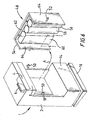
- Fig. 6 shows a further embodiment of the invention.
- the coin mechanism corresponds to that of the first embodiment except that coin stores, in the form of two coin storage tubes and a cashbox, are provided within a removable cassette, indicated generally by the reference numeral 48, rather than being attached directly to the body of the coin mechanism.
- the cassette 48 is mounted in a recess in the coin mechanism where hooks 50 on the mainframe engage pegs 52 on the cassette 48 to hold it in position.
- the removable cassette 48 comprises a support 54 on which are removably mounted coin stores in the form of two coin storage tubes 56, 58 and a cashbox 60.
- the support 54, the coin storage tubes 56, 58 and the means of mounting the tubes on the support are known, for example, from GB 2 246 897 , the contents of which document are incorporated herein by reference.
- the support 54 is generally channel-shaped with a front wall 62 and two side walls 64. On the inside of the front wall 62 are retaining means in the form of pairs of T-shaped projections 66 (see Figs. 7 and 9 ). With reference to Fig.
- each coin storage tube 56, 58 is provided with bars 68 which are made to engage respective pairs of T-shaped projections 66 on the support 54 when the tube is pushed into position in the direction indicated by arrow B, to mount the tube in a predetermined position.
- the components are dimensioned so that the retaining means are an interference fit and some manual force is required to push the tube in the direction of arrow B.
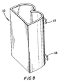
- the cashbox 60 is shown in more detail in Fig. 8 .
- the front part of the cashbox 60 is shaped so as to be similar to the front of two coin storage tubes side by side. More specifically, the front part of the cashbox 60 is shaped like two adjoining half-cylinders. The sides of the half-cylinders extend to the back part of the cashbox which is flat. The top of the cashbox 60 is open but the bottom is closed. The height of the cashbox 60 is the same as the height of each coin storage tube 56, 58 in the cassette 48.
- Each half-cylinder of the front part of the cashbox 60 is also provided with a pair of bars 68 for mounting the cashbox on the support 54 in the same way in which the coin storage tubes 56, 58 are mounted.
- the bars 68 engage T-shaped projections 66 on the support 54 to retain the cashbox 60 in a predetermined position.
- the coin validator 4 tests coins and the coin separator 8 routes acceptable coins according to their denomination determined by the testing section either to a respective coin storage tube 56, 58 for receiving one particular denomination or to the cashbox 60 if the proper coin storage tube is full or if the coin denomination involved is not one which is intended to be dispensed. Coins are dispensed as change from the bottom of the tubes. Coins are not dispensed as change from the cashbox 60.
- the serviceman removes the cassette 48 from the coin mechanism 1, then lifts the cashbox out of the cassette and turns the cashbox upside down to tip out the coins.
- the design of the cashbox 60, the tubes 56, 58 and the support 54, including the bars 68 and the projections 66, are such that the tubes 56, 58 can be interchanged, and the two tubes can be interchanged with the cashbox 60, so that various configurations of the cassette are possible.
- the tubes 56, 58 and/or the cashbox 60 can be interchanged with other tubes, for example, for storing coins of other denominations, or other cashboxes.
- the mechanism can be converted from one having entirely coin storage tubes to one having coin storage tubes and a cashbox and vice versa. It may be desirable in some circumstances to have a cashbox and no tubes, in which case the cashbox may take up the entire cassette.
- the serviceman reconfigures the coin mechanism to ensure that coins are correctly routed to the right store by inserting an appropriate code indicating the position of the various stores using a keypad (not shown) on the mechanism.
- the stores (including the cashbox) need not be removable from the cassette, in which case it is necessary to replace the cassette to change the configuration of the coin stores.
- the cassette and stores may be integrally moulded.
- the cashbox may include a means to allow it to be emptied while it is upright, for example, a door on a side of the cashbox which is accessible, for example, when the cassette is removed from the coin mechanism.
- the cassette housing may include a hinged opening to provide access to the cashbox from the outside of the coin mechanism without needing to remove the cassette. The cashbox can then still be emptied even if it is difficult or impossible to remove the cassette, for example, if the cassette is screwed in place.
- the cashbox can also be emptied by covering any top openings of the other stores and turning over the entire cassette to tip out the coins in the cashbox.
- a store may be interchangeable with another store.
- the cashbox can be any suitable shape, preferably one which maximises the capacity for storing coins.
- the cashbox can be formed to extend into space behind the coin storage tubes.
- other coin stores can be used in place of storage tubes such as, for example, stores which dispense change but do not receive coins from the validator.
- the mechanism or cassette may contain only a cashbox and no other stores.
Landscapes
- Physics & Mathematics (AREA)
- General Physics & Mathematics (AREA)
- Control Of Vending Devices And Auxiliary Devices For Vending Devices (AREA)
Description
- The invention relates to coin mechanisms, especially for use in vending machines and the like.
- In known coin-operated vending machines, a coin mechanism is provided for receiving and testing the acceptability of inserted coins. Acceptable coins are diverted either to one of a plurality of coin storage tubes, each for storing and dispensing in change coins of a respective denomination, or, if no coin tube is provided for a particular denomination because that denomination is not needed for change, or if the relevant tube is full, to a separate cashbox. The cashbox is situated remote from the coin mechanism, within the vending machine, but connected to it by a passageway. Coins are collected periodically from the cashbox by a serviceman. The coin storage tubes may be arranged within a cassette which is removable from and replaceable in the coin testing mechanism, as described, for example, in
GB-A-2 246 897 -
DE 41 21 985 A1 discloses a coin-operated games machine containing a symbol game device, a coin tester followed by individual coin collection containers, a banknote tester, a banknote collection container and a central controller. One coin collection container is a hopper with a coin output device controlled via the control unit by the banknote tester. The banknote tester can be selected via key control to operate as a banknote changer using the hopper or to activate the symbol game device -
US 5,056,643 discloses an arrangement including several cashier vending-type machines for goods and services. Each machine, in addition to having at least one cash box, also has not only several replaceable and preferably self-filling coin-storing units for returning or refunding money, but also has a computer that controls the machine, produces a balance, and is provided with a random access memory that is protected against the loss of power. To prevent deceitful manipulations by operators, and to enable a clear determination of error while precluding human error during use, without requiring additional work, each coin-storing unit is provided with an electronic memory that is protected against loss of data and that, upon insertion of that unit into a machine, stores a coding that identifies the machine. -
US 5,400,891 discloses a coin testing mechanism of the kind provided with a removable and replaceable cassette is described. The coin testing mechanism includes a plurality of coin storage tubes and means for dispensing coins from the storage tubes, and the removable cassette is an assembly which comprises a plurality of storage tube modules. Each of the modules comprises at least one storage tube, and the modules are retained in the assembly by releasable and reusable retaining means to enable exchanging one module of the cassette for another. -
EP 0 355 238 A1 discloses an assembly of a plurality of automatic product or service vending machines, for example travel ticket dispensers within a particular fare zone or ticket dispensers for a car-park company, each machine possessing, in addition to at least one cash box, a plurality of exchangeable, preferably self-replenishing coin stores for issuing change and a computer which controls the machine and produces a balance, and has write/read memories which are protected against power supply failure. In order to prevent dishonest manipulations by operating personnel and to enable errors to be clearly identified, with the elimination of human error from the analysis, and without additional work being necessary, each coin store is provided with an electronic memory which is protected against data loss and in which, each time the coin store is inserted in a machine, the code identifying this machine, for example the machine number, is stored. -
US 4,374,557 discloses a coin changer comprises a coin changer main part and an electronic type coin discrimination device which can be readily mounted to and detached from the coin changer main part. The electronic type coin discrimination device includes a detection coil for detecting characteristics of a deposited coin, a discrimination circuit for judging whether the deposited coin is a true coin or a counterfeit one in response to the output of the detection coil and produces a sole kind of discrimination signal representative of trueness or falsity of the coin regardless of the denomination of the coin, a true coin passage and a counterfeit coin passage provided behind the detection coil and a mechanical coin sort-out device provided in the true coin passage for sorting out coins by denomination. The coin changer main part comprises coin switches for detecting coins of respective denominations having been sorted out by the sort-out device, a coin receiving device for receiving the coins which have passed through the coin switches, a control circuit for effecting control operations including a money amount counting control, a vend control and a change payout control, and an electromagnetic device for distributing the deposited coin to either the true coin passage or the counterfeit coin passage in the coin discrimination device in response to the output of the discrimination circuit. This electromagnetic device distributes the coins by projecting or withdrawing a reject pin into or from a bifurcation of the true coin passage and the counterfeit coin passage. -
US 5,082,100 discloses a device comprising a housing with a front face provided with an admission slot for coins and with a coin return receptacle. A conveyor, situated in a shaft communicating by gravity with the return receptacle, transports the coins from the admission slot to a processing module. -
EP 0 351 295 A1 discloses another coin mechanism for ticket machines. Each coin tube has a code carrier. Further, output devices having storage means are provided for storing the value of coins contained in a coin tube. - The present invention provides a coin mechanism as defined in claim 1, and a vending machine comprising such a coin mechanism.
- Embodiments of the present invention are described below with reference to the accompanying drawings, of which:
-
Fig. 1 is a perspective view of a coin mechanism; -
Fig. 2 is a block diagram of the circuit of the mechanism; -
Fig. 3 is a cross-section along the line A-A ofFig. 1 ; -
Fig. 4 is a front view of part of a second coin mechanism; -
Fig. 5 is a perspective view of a cashbox; -
Fig. 6 is a perspective view of a third coin mechanism including a removable cassette; -
Fig. 7 is a view showing part of the cassette ofFig. 6 ; -
Fig. 8 is a perspective view of the cashbox shown inFig. 6 ; -
Fig. 9 is a cross-section along line I-I ofFigure 6 . - A first embodiment of the invention will be described with reference to
Figs. 1 ,2 and3 . -
Fig. 1 shows a coin mechanism, indicated generally by the reference numeral 1, for use in a vending machine (not shown). The coin mechanism includes a mainframe 2 supporting acoin validator 4 for testing the validity of coins inserted through acoin inlet 6 and acoin separator 8 for routing the inserted coins according to the outcome of the validity test. - The coin separator is connected to a coin storage section, indicated generally by the
reference numeral 10, and to acoin reject passageway 12 extending along the front left hand corner of the coin storage section. Below thecoin storage section 10, there is acoin dispensing section 14, for dispensing coins as change from the coin storage section. Acoin return tray 16 is arranged below the coin mechanism 1 for receiving coins from thereject passageway 12 or coins dispensed from thecoin storage section 10, to be collected, for example, by a customer. - Referring to
Fig. 2 , the circuit of the present embodiment of the invention incorporates amicroprocessor 18 connected to data and addressbuses - The
microprocessor 18 is connected via thebuses ROM 24 stores the program controlling the overall operation of themicroprocessor 18, and theRAM 26 is used by themicroprocessor 18 as a scratch-pad memory. - The
microprocessor 18, theROM 24 and theRAM 26 are, in the preferred embodiment, combined on a single integrated circuit. - The
microprocessor 18 may also be connected via thebuses - The
microprocessor 18 is also coupled via thebuses circuitry 30 includes user-operable switches, circuits for operating thedispenser 16 and the gates of thecoin separator 8, the circuitry of thecoin validator 4, and a display visible to a user of the apparatus for displaying an accumulated credit value and an indication when insufficient coins are stored to guarantee that change will be available. - The input/
output circuitry 30 also includes an interface between the control circuit of the apparatus and avending machine 32 to which it is connected, and a further interface to anaudit device 34. - In operation of the apparatus the
microprocessor 18 successively tests the signals from the validator to determine whether a coin has been inserted in the apparatus. When a credit has been accumulated, the microprocessor also tests signals from the vending machine to determine whether a vending operation has been carried out. In response to various signals received by themicroprocessor 18, various parts of the program stored in theROM 24 are carried out. The microprocessor is thus arranged to control the gates in theseparator 8 in order to deliver the coins to the required locations, and is also operable to cause appropriate information to be shown on the displays of the apparatus and to deliver signals to the vending machine to permit or prevent vending operations. The microprocessor is also operable to control the dispenser to deliver appropriate amounts of change. Theaudit device 34 maintains a record of the number of coins of each denomination received and dispensed by the apparatus. - The arrangement so far is quite conventional, and the details of particular structures suitable for using as various parts of the mechanism will therefore not be described in detail.
- The particular sequence of most of the operations carried out by the microprocessor may be the same as in previous apparatus. A suitable program to be stored in the
ROM 24 can therefore be designed by anyone familiar with the art. - The
coin storage section 10 comprises twocoin storage tubes cashbox 40, as shown in outline inFig. 1 . - The
coin storage tubes coin storage section 10 and extend between thecoin separator 8 and thecoin dispensing section 14, and are open at both ends. Coins enter thecoin storage tubes coin separator 8, are stored within the tubes in a stack face to face and are dispensed from the tubes at the other end. Associated with each coin storage tube are pairs of coin level sensors (not shown) for detecting when the stack of coins within a tube exceeds a first, higher, level or is below a second, lower, level. - The
cashbox 40 is arranged in the left half of thecoin storage section 10, partially behind thereject passageway 12, and it extends between thecoin separator 8 and thecoin dispensing section 14. Thecashbox 40 has four walls, a base, and is open at the top, to receive coins from theseparator 8. The width of thecashbox 40 is approximately twice that of each of thecoin storage tubes cashbox 40 is inclined downwardly towards the front, as shown inFig. 3 . At the lower end of the front wall of the cashbox there is aslidable door 42, which is behind and approximately the same width as thereject passageway 12. Thedoor 42 is slidable up and down using ahandle 44 which extends through and is movable within aslot 46 in the front wall of thecoin storage section 10 next to thereject passageway 12. When thedoor 42 is open, thecashbox 40 opens into thereject passageway 12. - The
cashbox 40 and thecoin storage tubes - The
coin dispensing section 14 comprises two dispensers, each arranged underneath a respectivecoin storage tube - The coin mechanism 1 is configured to determine which denominations of coins are acceptable, and of those acceptable denominations, which denominations are to be directed to the
cashbox 40 and which denominations to thecoin storage tubes coin storage tube 36, 10p coins are to be stored in the secondcoin storage tube 38 and the other acceptable denominations are to be stored in thecashbox 40. - In operation, a coin inserted into the
coin inlet 6 rolls into thevalidator 4 and is subjected there to various tests to determine if it is a coin of a denomination deemed acceptable by the mechanism, in accordance with known techniques. If the coin is an acceptable coin it is directed by a gate within thecoin validator 4 to thecoin separator 8 which includes gates which are operated according to the outcome of the tests in the validator to determine the subsequent path of the coin, as is known. If the coin is not an acceptable coin, it is directed by the gate within thecoin validator 4 to thecoin reject passageway 12, which leads outside thecoin storage section 10 and the dispensingsection 14 to thecoin return tray 16. If the coin is one of the denominations for which acoin storage tube separator 8 directs the coin to the relevant tube. If the relevant tube is full, or if the coin is one of the other acceptable denominations, then theseparator 8 directs the coin along a path (or one of a plurality of paths) that leads to thecashbox 40. In a known manner, when a coin of a given denomination is needed for change, thedispensers 14 remove a single coin from the bottom of the stack of coins within thetube section 14 into thecoin return tray 16. - Over time, coins accumulate within the
cashbox 40, because coins are not dispensed as change from it. As shown, the coins in the cashbox are not stored in an ordered manner, such as a stack as in the coin tubes, but in a disordered fashion. Periodically, a serviceman visits the mechanism to empty thecashbox 40. This is done by moving thehandle 44 upwards, which causes thedoor 42 of thecashbox 40 to open. Because the base of thecashbox 40 is inclined downwardly towards thedoor 42, coins slide from the cashbox into thereject passageway 12 and thence to thecoin return tray 16. The coins are collected from thecoin return tray 16. - In an alternative embodiment, shown in
Figs. 4 and 5 , thecashbox 40a is arranged in the right side of thecoin storage section 10, away from thecoin reject passageway 12. The twocoin tubes coin storage section 10. As shown inFig. 5 , the base of thecashbox 40a is in the form of aslidable tray 47, which extends through the front of thecoin storage section 10 so that one end can be grasped from outside to move it. Underneath thecashbox 40, there is a space (not shown) through the dispensingsection 14, so that when thetray 47 is pulled out to open the base of thecashbox 40a, coins drop straight from thecashbox 40a into thecoin return tray 16 and can be collected as above. Alternatively, chutes may be arranged below thecashbox 40a, which connect to thereject route 12, so that coins emptied from thecashbox 40a, when the base of the cashbox is open, are directed to the reject route, or to any other suitable path to allow the coins to be collected. - At least part of the front of the housing in the coin storage section may be removable, or provided with a door, so that at least part of the cashbox is exposed. In that case, the cashbox may have a hinged door on its front wall allowing the coins in the cashbox to be removed. Alternatively, all of the front of the housing in the coin storage section may be removable, to expose the cashbox and the coin storage tubes. The cashbox may be so mounted that it can be removed from the housing and can be emptied simply by turning it upside down. Especially if the storage tubes are also removably mounted, the cashbox can be replaced with a different cashbox, for example, one of a different shape and size. For example, the cashbox in the example given above could be replaced with a larger cashbox, occupying space equivalent to that of three coin storage tubes, and with one coin storage tube provided for change instead of two. Alternatively, a cashbox may take up all the space within the coin storage area, with no coin storage tubes provided. If the stores within the coin mechanism are changed, corresponding alterations to the routing and dispensing of coins may be necessary.
-
Fig. 6 shows a further embodiment of the invention. In this embodiment, the coin mechanism corresponds to that of the first embodiment except that coin stores, in the form of two coin storage tubes and a cashbox, are provided within a removable cassette, indicated generally by thereference numeral 48, rather than being attached directly to the body of the coin mechanism. - The
cassette 48 is mounted in a recess in the coin mechanism where hooks 50 on the mainframe engage pegs 52 on thecassette 48 to hold it in position. - In more detail, the
removable cassette 48 comprises asupport 54 on which are removably mounted coin stores in the form of twocoin storage tubes cashbox 60. Thesupport 54, thecoin storage tubes GB 2 246 897 support 54 is generally channel-shaped with afront wall 62 and twoside walls 64. On the inside of thefront wall 62 are retaining means in the form of pairs of T-shaped projections 66 (seeFigs. 7 and 9 ). With reference toFig. 7 , eachcoin storage tube bars 68 which are made to engage respective pairs of T-shapedprojections 66 on thesupport 54 when the tube is pushed into position in the direction indicated by arrow B, to mount the tube in a predetermined position. The components are dimensioned so that the retaining means are an interference fit and some manual force is required to push the tube in the direction of arrow B. - The
cashbox 60 is shown in more detail inFig. 8 . The front part of thecashbox 60 is shaped so as to be similar to the front of two coin storage tubes side by side. More specifically, the front part of thecashbox 60 is shaped like two adjoining half-cylinders. The sides of the half-cylinders extend to the back part of the cashbox which is flat. The top of thecashbox 60 is open but the bottom is closed. The height of thecashbox 60 is the same as the height of eachcoin storage tube cassette 48. - Each half-cylinder of the front part of the
cashbox 60 is also provided with a pair ofbars 68 for mounting the cashbox on thesupport 54 in the same way in which thecoin storage tubes Fig. 9 , which shows thecashbox 60 mounted on thesupport 54 in cross-section, thebars 68 engage T-shapedprojections 66 on thesupport 54 to retain thecashbox 60 in a predetermined position. - As before, in operation, the
coin validator 4 tests coins and thecoin separator 8 routes acceptable coins according to their denomination determined by the testing section either to a respectivecoin storage tube cashbox 60 if the proper coin storage tube is full or if the coin denomination involved is not one which is intended to be dispensed. Coins are dispensed as change from the bottom of the tubes. Coins are not dispensed as change from thecashbox 60. - To empty the
cashbox 60, the serviceman removes thecassette 48 from the coin mechanism 1, then lifts the cashbox out of the cassette and turns the cashbox upside down to tip out the coins. - The design of the
cashbox 60, thetubes support 54, including thebars 68 and theprojections 66, are such that thetubes cashbox 60, so that various configurations of the cassette are possible. Also, thetubes cashbox 60 can be interchanged with other tubes, for example, for storing coins of other denominations, or other cashboxes. Thus, for example, the mechanism can be converted from one having entirely coin storage tubes to one having coin storage tubes and a cashbox and vice versa. It may be desirable in some circumstances to have a cashbox and no tubes, in which case the cashbox may take up the entire cassette. When the cassette of an existing coin mechanism is altered in any of the above ways, the serviceman reconfigures the coin mechanism to ensure that coins are correctly routed to the right store by inserting an appropriate code indicating the position of the various stores using a keypad (not shown) on the mechanism. - Various modifications to the second embodiment are possible.
- For example, the stores (including the cashbox) need not be removable from the cassette, in which case it is necessary to replace the cassette to change the configuration of the coin stores. The cassette and stores may be integrally moulded.
- The cashbox may include a means to allow it to be emptied while it is upright, for example, a door on a side of the cashbox which is accessible, for example, when the cassette is removed from the coin mechanism. The cassette housing may include a hinged opening to provide access to the cashbox from the outside of the coin mechanism without needing to remove the cassette. The cashbox can then still be emptied even if it is difficult or impossible to remove the cassette, for example, if the cassette is screwed in place. The cashbox can also be emptied by covering any top openings of the other stores and turning over the entire cassette to tip out the coins in the cashbox.
- In either embodiment, a store (whether a cashbox or other store) may be interchangeable with another store. Although it is easier, for example, to fit the cashbox into an existing cassette if it is shaped like a tube, the cashbox can be any suitable shape, preferably one which maximises the capacity for storing coins. For example, the cashbox can be formed to extend into space behind the coin storage tubes. Also, other coin stores can be used in place of storage tubes such as, for example, stores which dispense change but do not receive coins from the validator. The mechanism or cassette may contain only a cashbox and no other stores.
Claims (2)
- A coin mechanism comprising
coin dispensing means (14),
a cashbox (40) arranged in use above the coin dispensing means, wherein the cashbox is a multi-denominational store for receiving and storing coins of a plurality of denominations, wherein the cashbox is not dispensing coins as change, and wherein the coins in the cashbox are not stored in an ordered manner,
at least one coin store (36, 38; 56, 58) for dispensing coins as change, which is arranged for storing coins of one denomination only,
a coin reject path (12), and
a coin return tray (16),
characterized by means for allowing coins to be removed from the cashbox (40) in place within the coin mechanism, wherein the cashbox (40) comprises a door (42) to enable coins to be removed from the cashbox (40),
wherein coins are removable from the cashbox by way of the coin reject path (12) and the coin return tray (16), and
wherein the cashbox (40) is in a cassette (48) which is removable from and replaceable in the coin mechanism. - A vending machine comprising a coin mechanism according to claim 1.
Applications Claiming Priority (2)
| Application Number | Priority Date | Filing Date | Title |
|---|---|---|---|
| GB9726861A GB2332552B (en) | 1997-12-18 | 1997-12-18 | Coin mechanism |
| GB9726861 | 1997-12-18 |
Publications (3)
| Publication Number | Publication Date |
|---|---|
| EP0924660A2 EP0924660A2 (en) | 1999-06-23 |
| EP0924660A3 EP0924660A3 (en) | 2001-01-31 |
| EP0924660B1 true EP0924660B1 (en) | 2012-11-21 |
Family
ID=10823901
Family Applications (1)
| Application Number | Title | Priority Date | Filing Date |
|---|---|---|---|
| EP98309877A Expired - Lifetime EP0924660B1 (en) | 1997-12-18 | 1998-12-02 | Coin mechanism |
Country Status (5)
| Country | Link |
|---|---|
| US (1) | US6165064A (en) |
| EP (1) | EP0924660B1 (en) |
| JP (1) | JPH11250299A (en) |
| ES (1) | ES2396217T3 (en) |
| GB (1) | GB2332552B (en) |
Families Citing this family (16)
| Publication number | Priority date | Publication date | Assignee | Title |
|---|---|---|---|---|
| US6585581B2 (en) * | 2000-02-11 | 2003-07-01 | Mag-Nif Incorporated | Coin sorting apparatus with reciprocating coin pushing member |
| US7048623B2 (en) * | 2001-02-09 | 2006-05-23 | Mag-Nif Incorporated | Coin separator and sorter assembly |
| US6638157B2 (en) * | 2001-06-12 | 2003-10-28 | Mag-Nif Incorporated | Five coin bank |
| JP2002352287A (en) * | 2001-05-28 | 2002-12-06 | Nippon Signal Co Ltd:The | Device for storing non-contact token |
| US7992699B2 (en) * | 2003-04-10 | 2011-08-09 | Talaris Inc. | Machine and method for cash recycling and cash settlement |
| ES2238908B1 (en) * | 2003-07-30 | 2006-11-16 | Proindumar, S.L. | AUTOMATIC SYSTEM OF CONTROL AND TRANSVASE OF COINS, APPLICABLE TO PAYERS OF RECREATIONAL AND SIMILAR MACHINES. |
| EP1526483B1 (en) * | 2003-10-21 | 2011-11-30 | Asahi Seiko Co. Ltd. | Automatic coin aligning apparatus |
| ES2245582A1 (en) * | 2004-01-15 | 2006-01-01 | Jofemar, S.A. | GROUPING ASSEMBLY OF VALIDATION AND RETURN / PAYMENT COINS MECHANISMS. |
| DE602004030990D1 (en) * | 2004-01-15 | 2011-02-24 | Jofemar Sa | Device for checking and dispensing coins |
| GB2416061A (en) * | 2004-07-07 | 2006-01-11 | Money Controls Ltd | Coin accepting and dispensing apparatus |
| US8498736B2 (en) * | 2008-01-29 | 2013-07-30 | Glory Ltd. | Coin handling machine |
| US9196106B2 (en) * | 2011-12-30 | 2015-11-24 | MerchSource, LLC | Automatic coin sorting device |
| DE102012112344B4 (en) * | 2012-12-14 | 2014-07-03 | Löwen Entertainment GmbH | Coin box for a money-operated device |
| JP6088693B1 (en) * | 2016-05-19 | 2017-03-01 | 東芝テック株式会社 | Money processing equipment |
| WO2018183925A1 (en) * | 2017-03-30 | 2018-10-04 | Tidel Engineering L.P. | Systems and methods for coin recycling |
| ES2856260T3 (en) * | 2018-03-19 | 2021-09-27 | Crane Payment Innovations Ltd | Coin collector |
Family Cites Families (23)
| Publication number | Priority date | Publication date | Assignee | Title |
|---|---|---|---|---|
| CA808991A (en) * | 1969-03-25 | H. Griesemer Raymond | Coin handling device | |
| US1076584A (en) * | 1908-07-27 | 1913-10-21 | J G Brill Co | Fare-box. |
| FR1317326A (en) * | 1961-12-28 | 1963-02-08 | Coin sorter device | |
| CH601870A5 (en) * | 1976-07-19 | 1978-07-14 | Autelca Ag | |
| GB2065949B (en) * | 1979-10-08 | 1984-05-16 | Nippon Coinco Co Ltd | Coin dispensing apparatus |
| JPS5673060U (en) * | 1979-11-12 | 1981-06-16 | ||
| JPS639019Y2 (en) * | 1979-11-22 | 1988-03-17 | ||
| CH661091A5 (en) * | 1982-11-22 | 1987-06-30 | Sodeco Compteurs De Geneve | LOCKING MECHANISM ON A LID CASSETTE. |
| GB2140187B (en) * | 1983-05-13 | 1986-08-06 | Knight Technology Ltd | Apparatus for testing and routing coins |
| DE3576007D1 (en) * | 1984-11-05 | 1990-03-15 | Ascom Autelca Ag | CASH SAFE. |
| FR2609341B1 (en) * | 1987-01-06 | 1989-03-03 | Cga Hbs | CURRENCY RETURN AUTOMATIC DISTRIBUTOR |
| EP0310429B1 (en) * | 1987-10-01 | 1992-12-02 | Sanden Corporation | Coin handling apparatus |
| DE3802253C2 (en) * | 1988-01-27 | 1995-08-24 | Nsm Ag | Coin-operated entertainment machine |
| FR2634301B1 (en) * | 1988-07-15 | 1992-05-22 | Dassault Electronique | DEVICE FOR PROCESSING COINS |
| US5021026A (en) * | 1988-07-22 | 1991-06-04 | Laurel Bank Machines Co., Ltd. | Coin receiving and dispensing machine |
| EP0355238B1 (en) * | 1988-08-25 | 1993-07-28 | Scheidt & Bachmann Gmbh | Assembly of a plurality of product or service vending machines |
| JP2740979B2 (en) * | 1990-04-04 | 1998-04-15 | 株式会社日本コンラックス | Vending machine control device |
| GB2246897B (en) | 1990-08-10 | 1994-04-13 | Mars Inc | Coin testing mechanism |
| EP0477722B1 (en) * | 1990-09-20 | 2000-03-22 | Kabushiki Kaisha Nippon Conlux | Coin processing apparatus |
| DE4121985A1 (en) * | 1991-01-23 | 1992-07-30 | Nsm Ag | Coin-operated games machine - enables coin collection hopper output device to be controlled by banknote tester to allow change provision for banknote |
| GB2262982B (en) * | 1991-10-16 | 1995-05-10 | Mars Inc | Coin mechanism having coin level sensor |
| JP2781495B2 (en) * | 1992-06-19 | 1998-07-30 | アルゼ株式会社 | Coin payout device |
| GB2284090B (en) * | 1993-11-17 | 1997-03-26 | Mars Inc | Method and apparatus for controlling the dispensing of money |
-
1997
- 1997-12-18 GB GB9726861A patent/GB2332552B/en not_active Expired - Fee Related
-
1998
- 1998-12-02 ES ES98309877T patent/ES2396217T3/en not_active Expired - Lifetime
- 1998-12-02 EP EP98309877A patent/EP0924660B1/en not_active Expired - Lifetime
- 1998-12-10 US US09/209,510 patent/US6165064A/en not_active Expired - Lifetime
- 1998-12-18 JP JP10359888A patent/JPH11250299A/en active Pending
Also Published As
| Publication number | Publication date |
|---|---|
| GB2332552A (en) | 1999-06-23 |
| US6165064A (en) | 2000-12-26 |
| EP0924660A3 (en) | 2001-01-31 |
| GB2332552B (en) | 2002-01-30 |
| JPH11250299A (en) | 1999-09-17 |
| EP0924660A2 (en) | 1999-06-23 |
| GB9726861D0 (en) | 1998-02-18 |
| ES2396217T3 (en) | 2013-02-20 |
Similar Documents
| Publication | Publication Date | Title |
|---|---|---|
| US6165064A (en) | Coin mechanism with cashbox arranged above coin dispensing means | |
| US20040249501A1 (en) | Enhanced bill acceptor/dispenser for vending machines | |
| EP1805728B1 (en) | Money item dispensing apparatus | |
| EP0755033A1 (en) | Amusement machine | |
| WO1998016910A1 (en) | Gaming machine currency apparatus and method therefore | |
| CA2128542C (en) | Slot machine having unitary coin restoration system | |
| US20020195309A1 (en) | Money handling apparatus and method | |
| US6994202B1 (en) | Money acceptance method and apparatus | |
| GB2326504A (en) | Currency handling apparatus capable of predicting future cash demands | |
| EP0988621B1 (en) | Currency handling apparatus | |
| EP0993661B1 (en) | Method of operating a coin mechanism | |
| EP1220169B1 (en) | Cash handling machine | |
| EP0167181B1 (en) | Coin handling apparatus | |
| CA2528621C (en) | Enhanced bill acceptor/dispenser for vending machines | |
| EP1031950A1 (en) | Currency handling apparatus | |
| JP2686923B2 (en) | Change control management device for vending machines | |
| JPS6236596B2 (en) | ||
| JP3436282B2 (en) | Currency exchange machine with a function to prevent forgetting to take bills and coins | |
| JP3869614B2 (en) | Coin processing equipment | |
| GB2161007A (en) | Coin-released machines | |
| JP3185986B2 (en) | Cash out device | |
| JP2539730B2 (en) | Coin recycling device | |
| JPH0246882A (en) | Pachinko device | |
| JP3036607U (en) | Ticket vending machine for amusement machines | |
| JP2505764Y2 (en) | Coin processing equipment |
Legal Events
| Date | Code | Title | Description |
|---|---|---|---|
| PUAI | Public reference made under article 153(3) epc to a published international application that has entered the european phase |
Free format text: ORIGINAL CODE: 0009012 |
|
| AK | Designated contracting states |
Kind code of ref document: A2 Designated state(s): DE ES FR GB IT |
|
| AX | Request for extension of the european patent |
Free format text: AL;LT;LV;MK;RO;SI |
|
| PUAL | Search report despatched |
Free format text: ORIGINAL CODE: 0009013 |
|
| AK | Designated contracting states |
Kind code of ref document: A3 Designated state(s): AT BE CH CY DE DK ES FI FR GB GR IE IT LI LU MC NL PT SE |
|
| AX | Request for extension of the european patent |
Free format text: AL;LT;LV;MK;RO;SI |
|
| RIC1 | Information provided on ipc code assigned before grant |
Free format text: 7G 07F 5/24 A |
|
| 17P | Request for examination filed |
Effective date: 20010727 |
|
| AKX | Designation fees paid |
Free format text: DE ES FR GB IT |
|
| 17Q | First examination report despatched |
Effective date: 20050525 |
|
| RAP1 | Party data changed (applicant data changed or rights of an application transferred) |
Owner name: MEI, INC. |
|
| 111Z | Information provided on other rights and legal means of execution |
Free format text: DEESFRGBIT Effective date: 20061103 |
|
| 111Z | Information provided on other rights and legal means of execution |
Free format text: DE ES FR GB IT Effective date: 20070802 |
|
| APBK | Appeal reference recorded |
Free format text: ORIGINAL CODE: EPIDOSNREFNE |
|
| APBN | Date of receipt of notice of appeal recorded |
Free format text: ORIGINAL CODE: EPIDOSNNOA2E |
|
| APBR | Date of receipt of statement of grounds of appeal recorded |
Free format text: ORIGINAL CODE: EPIDOSNNOA3E |
|
| APAF | Appeal reference modified |
Free format text: ORIGINAL CODE: EPIDOSCREFNE |
|
| APBT | Appeal procedure closed |
Free format text: ORIGINAL CODE: EPIDOSNNOA9E |
|
| GRAP | Despatch of communication of intention to grant a patent |
Free format text: ORIGINAL CODE: EPIDOSNIGR1 |
|
| R11X | Information provided on other rights and legal means of execution (corrected) |
Free format text: DE ES FR GB IT Effective date: 20070802 |
|
| GRAS | Grant fee paid |
Free format text: ORIGINAL CODE: EPIDOSNIGR3 |
|
| GRAA | (expected) grant |
Free format text: ORIGINAL CODE: 0009210 |
|
| AK | Designated contracting states |
Kind code of ref document: B1 Designated state(s): DE ES FR GB IT |
|
| REG | Reference to a national code |
Ref country code: GB Ref legal event code: FG4D |
|
| REG | Reference to a national code |
Ref country code: DE Ref legal event code: R096 Ref document number: 69842893 Country of ref document: DE Effective date: 20130117 |
|
| REG | Reference to a national code |
Ref country code: ES Ref legal event code: FG2A Ref document number: 2396217 Country of ref document: ES Kind code of ref document: T3 Effective date: 20130220 |
|
| PGFP | Annual fee paid to national office [announced via postgrant information from national office to epo] |
Ref country code: FR Payment date: 20130107 Year of fee payment: 15 |
|
| PLBE | No opposition filed within time limit |
Free format text: ORIGINAL CODE: 0009261 |
|
| STAA | Information on the status of an ep patent application or granted ep patent |
Free format text: STATUS: NO OPPOSITION FILED WITHIN TIME LIMIT |
|
| 26N | No opposition filed |
Effective date: 20130822 |
|
| REG | Reference to a national code |
Ref country code: DE Ref legal event code: R097 Ref document number: 69842893 Country of ref document: DE Effective date: 20130822 |
|
| PGFP | Annual fee paid to national office [announced via postgrant information from national office to epo] |
Ref country code: DE Payment date: 20131127 Year of fee payment: 16 Ref country code: GB Payment date: 20131127 Year of fee payment: 16 |
|
| PGFP | Annual fee paid to national office [announced via postgrant information from national office to epo] |
Ref country code: IT Payment date: 20131210 Year of fee payment: 16 Ref country code: ES Payment date: 20131112 Year of fee payment: 16 |
|
| REG | Reference to a national code |
Ref country code: FR Ref legal event code: ST Effective date: 20140829 |
|
| PG25 | Lapsed in a contracting state [announced via postgrant information from national office to epo] |
Ref country code: FR Free format text: LAPSE BECAUSE OF NON-PAYMENT OF DUE FEES Effective date: 20131231 |
|
| REG | Reference to a national code |
Ref country code: DE Ref legal event code: R119 Ref document number: 69842893 Country of ref document: DE |
|
| GBPC | Gb: european patent ceased through non-payment of renewal fee |
Effective date: 20141202 |
|
| PG25 | Lapsed in a contracting state [announced via postgrant information from national office to epo] |
Ref country code: DE Free format text: LAPSE BECAUSE OF NON-PAYMENT OF DUE FEES Effective date: 20150701 Ref country code: GB Free format text: LAPSE BECAUSE OF NON-PAYMENT OF DUE FEES Effective date: 20141202 |
|
| PG25 | Lapsed in a contracting state [announced via postgrant information from national office to epo] |
Ref country code: IT Free format text: LAPSE BECAUSE OF NON-PAYMENT OF DUE FEES Effective date: 20141202 |
|
| REG | Reference to a national code |
Ref country code: ES Ref legal event code: FD2A Effective date: 20160126 |
|
| PG25 | Lapsed in a contracting state [announced via postgrant information from national office to epo] |
Ref country code: ES Free format text: LAPSE BECAUSE OF NON-PAYMENT OF DUE FEES Effective date: 20141203 |