EP0924535A2 - Opto-electronic sensor - Google Patents
Opto-electronic sensor Download PDFInfo
- Publication number
- EP0924535A2 EP0924535A2 EP98124137A EP98124137A EP0924535A2 EP 0924535 A2 EP0924535 A2 EP 0924535A2 EP 98124137 A EP98124137 A EP 98124137A EP 98124137 A EP98124137 A EP 98124137A EP 0924535 A2 EP0924535 A2 EP 0924535A2
- Authority
- EP
- European Patent Office
- Prior art keywords
- lens
- light
- zone
- multifocus
- sensor according
- Prior art date
- Legal status (The legal status is an assumption and is not a legal conclusion. Google has not performed a legal analysis and makes no representation as to the accuracy of the status listed.)
- Granted
Links
Images


Classifications
-
- G—PHYSICS
- G01—MEASURING; TESTING
- G01S—RADIO DIRECTION-FINDING; RADIO NAVIGATION; DETERMINING DISTANCE OR VELOCITY BY USE OF RADIO WAVES; LOCATING OR PRESENCE-DETECTING BY USE OF THE REFLECTION OR RERADIATION OF RADIO WAVES; ANALOGOUS ARRANGEMENTS USING OTHER WAVES
- G01S7/00—Details of systems according to groups G01S13/00, G01S15/00, G01S17/00
- G01S7/48—Details of systems according to groups G01S13/00, G01S15/00, G01S17/00 of systems according to group G01S17/00
- G01S7/481—Constructional features, e.g. arrangements of optical elements
- G01S7/4811—Constructional features, e.g. arrangements of optical elements common to transmitter and receiver
-
- G—PHYSICS
- G01—MEASURING; TESTING
- G01S—RADIO DIRECTION-FINDING; RADIO NAVIGATION; DETERMINING DISTANCE OR VELOCITY BY USE OF RADIO WAVES; LOCATING OR PRESENCE-DETECTING BY USE OF THE REFLECTION OR RERADIATION OF RADIO WAVES; ANALOGOUS ARRANGEMENTS USING OTHER WAVES
- G01S17/00—Systems using the reflection or reradiation of electromagnetic waves other than radio waves, e.g. lidar systems
- G01S17/02—Systems using the reflection of electromagnetic waves other than radio waves
- G01S17/04—Systems determining the presence of a target
Definitions
- the invention relates to an opto-electronic sensor for monitoring a room area, in particular a reflection light sensor, with a Transmitter for emitting a transmission light beam along a transmission axis, with a receiving optics and with a receiving element.
- Such sensors are used to detect diffusely reflecting or remitting Objects in a region surrounding a section of the transmitted light beam Surveillance area. If one in the surveillance area Object part of the transmitted light in the direction of the receiving optics reflected, this is directed to the receiving element, so that this generates a corresponding received signal.
- the spatial limitation is a disadvantage of known sensors of this type your surveillance area: According to the imaging properties In the receiving optics, objects are only along a restricted path Range of the transmission axis detected. For sensors with pupil division the problem arises that this is from close to the sensor on the transmit axis arranged objects reflected or reflected light Receiving element no longer reached.
- the object is achieved in that the receiving optics to enlarge the surveillance area with a multifocus lens has several zones of different focal points, the one Zone that is used for the mapping of a surveillance close range to the Receiving element is effective, a smaller distance from the transmission axis has as that zone which is used for the imaging of a surveillance remote area is effective on the receiving element, and wherein the multifocus lens is asymmetrical.
- a zone of the multifocus lens for a portion of the surveillance area is effective, the light from one in this section object is reflected or remitted and the zone acted upon by this at least largely on the receiving element redirected.
- the asymmetrical multifocus lens according to the invention has in particular no rotational symmetry with respect to the transmission axis and no mirror symmetry with respect to a plane that is perpendicular to the transmission axis stands.
- such a multifocus lens is still considered to be according to the invention, which is mirror symmetric with respect to a plane parallel to the transmission axis runs or contains it.
- the inventive design of the receiving optics with several the monitoring area becomes spatially separated focal points effectively expanded. Due to the asymmetrical structure of the Multifocus lens can be designed with different zones Focal points in contrast to, for example, rotationally symmetrical Realize multifocus lenses particularly easily.
- the monitoring area can advantageously be particularly advantageous can be expanded effectively in the direction of the sensor.
- the light falls of the reflecting object namely at a small angle relative to the transmission axis on this zone, so that with varying distance of the object a strong change in the deflection angle and thus a Reduction in the amount of light acting on the receiving element is effectively reduced.
- Due to the asymmetrical structure of the multifocus lens can be a small distance between the transmission beam and the zone effective for the imaging of a surveillance close range to suppress the effect of reduced light exposure realize particularly simple way.
- the sensor according to the invention is constructed in pupil division, that is, with different transmission and reception axis, under perception the advantages associated with this structure, such as the exclusion of optical crosstalk through internal reflections and / or by backscattering caused by contamination of the optical Interfaces are caused.
- the sensor according to the invention has the advantage an expansion that has taken place in particular in the direction of the reception optics of the surveillance area.
- the invention further enables the zones of the multifocus lens or to provide their focal points in such a way that spatially essentially mutually spaced sections of the monitoring area arise.
- the multifocus lens integrally formed. It preferably consists of a single, essentially homogeneous material. Such a configuration of the Multifocus lens enables a particularly simple manufacture and Handling the same.
- the multifocus lens can be made from a material of homogeneous Refractive index be made, the different zones with their realized by the respective surface design and thickness differing imaging properties substantially from are delimited from each other.
- the multifocus lens as a gradient lens. In this case there is a continuous transition of the imaging properties from one zone to another zone.
- the invention Sensor has a pilot transmitter, for example a red LED, for transmission of a visible pilot light beam substantially parallel to that Transmitter axis of the transmitter. This enables the sensor or its monitoring area can be adjusted easily.
- the invention Design of the sensor with an asymmetrical multifocus lens facilitated the integration of such a pilot transmitter in the sensor, wherein the pilot light beam with the simplest optical means very close to the Transmission axis can be guided.
- the senor has one Measuring device, for example a time-of-flight measuring device, for determination the distance of an object within the surveillance area from the sensor.
- a Measuring device for example a time-of-flight measuring device, for determination the distance of an object within the surveillance area from the sensor.
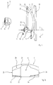
- Fig. 1 shows schematically a perspective side view of parts of a sensor according to the invention.
- the sensor has an infrared laser diode as transmitter 1 with attached collimator lens unit 2 for transmission of a transmission light beam along a transmission axis 3.
- An asymmetrically shaped reception multifocus lens 4 which is essentially a main direction of vertical extension in Fig. 1 5, has at its end facing the transmission axis 3 a semi-cylindrical recess 6. Grips around this recess 6 the multifocus lens 4 the collimator lens unit 2 such that its main direction of extension 5 is substantially perpendicular to the Transmission axis 3.
- the exact structural design of the multifocus lens 4 is explained in more detail below with reference to FIGS. 2a to 2c.
- Transmitter 1 On the opposite side of the multifocus lens 4 Transmitter 1 is a pilot transmitter light-emitting diode 10 with a pilot beam lens 11 arranged to emit a pilot light beam along a pilot beam transmission axis 12, which runs essentially parallel to the transmission axis 3. In the transmission direction of the pilot beam lens 11 and the multifocus lens 4 there is a flat protective disk 13.
- Fig. 1 means not shown in their position relative to each other within of a housing, the front of which is partially covered by the protective pane 13 is formed.
- the sensor shown in Fig. 1 serves as a reflection light scanner for detection of objects within a surveillance area that are essentially with one by imaging the transmitted light beam by the collimator lens unit 2 predetermined lateral extent extends along the transmission axis 3. If an object from the light of the Transmitter 1 is detected, it reflects this diffusely in the direction of Multifocus lens 4. Through its different zones, the reflected Light depending on the distance of the object from the sensor to the Receiving collective lens 7 and deflected by this onto the receiving element 9. This generates depending on the received light intensity an output signal, for example for comparison with a Threshold value forwarded to an evaluation unit, not shown in FIG. 1 can be.
- the mode of operation of the different zones of the multifocus lens 4 is explained below with reference to FIGS. 3a to 5b.
- the receiving collective lens 7 has a short focal length and is immediate arranged in front of the receiving element 9. Your hemispherical The light entry side has an opening area that is significantly larger than the photosensitive surface of the receiving element 9, for example by a factor of 10 to 100. This will change the size of the photosensitive Virtually increased area or can be the photosensitive area of the Receiving elements 9 to achieve a low level of electronic noise be kept really low.
- the reception collective lens enables 7 the compensation of adjustment errors between the transmission axis 3 and the optical axes of the light exit sides 22, 23, 24 of the different zones of the multifocus lens 4 up to ⁇ 3 °, and it allows thus easier and faster assembly of the sensor. Through the Use of the receiving collective lens 7 can also be less Reach the depth of the sensor.
- the pilot transmitter 10, 11 sends a visible pilot light beam along the Axis 12 off, the adjustment of the transmitter 1 and thus the sensor simplified.
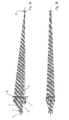
- Figures 2a, 2b and 2c show perspective side views and a view of the underside of the multifocus lens 4 of the sensor according to Fig. 1.
- the multifocus lens 4 has a light entry side 20 with a single aspherical surface. One opposite the light entry side 20
- the light exit side 21 of the multifocus lens 4 has three flat surfaces 22, 23, 24, which are each one for the illustration of a particular one Section of the monitoring area assigned to the effective zone are.
- the plane surface 22 for mapping a remote monitoring area effective zone takes up the majority of the light exit side 21 on.
- This remote plane surface 22 extends essentially within one plane perpendicular to the transmission axis 3 approximately to the level of Recess 6.
- the two close at this end of the plane surface 22 Flat surfaces 23, 24, which those zones of the multifocus lens 4th limit the side for imaging a surveillance close range or extremely close range are effective.
- the two flat surfaces 23, 24 each extend substantially opposite one side of the recess 6 from the end of the distal plane surface 22 the main direction of extent 5 to the height of the transmission axis 3.
- the surface normal of the near plane surface 23 is at an angle of approximately 91 ° to the main direction of extent 5 and closes with the transmission axis 3 an angle of approximately 5 °.
- the surface normal of the extreme near plane surface 24 includes with the main direction of extension 5 Angle of about 91.5 ° and with the transmission axis 3 an angle of about 11 °.
- the edge adjacent to the long plane surface 22 the near plane surface 23 and the extreme near plane surface 24 is in the direction the light entry side 20 of the multifocus lens 4.
- the three flat surfaces 22, 23, 24 are laterally parallel by one both to the transmission axis 3 and to the main direction of extent 5 running flat side surface 25 or 26 limited.
- FIG. 2c shows the underside of the multifocus lens 4 in a view in Main direction of extension 5.
- the underside of the for the illustration of a Zone or an extreme near zone effective zone has in each case roughly the outline of a trapezoid, the one on the light entry side 20 of the multifocus lens 4 adjacent side is curved accordingly the aspherical course of the surface 20.
- the view according to FIG. 2c is also the tilting of the near and extreme near plane surface 23 or 24 with respect to the main direction of extent 5.
- the tendencies the plane surfaces 23, 24 with respect to the transmission axis 3 or the main direction of extension 5 can also be chosen differently, depending on the desired Mapping properties of the corresponding zones.
- Figures 3a and 3b, 4a and 4b, and 5a and 5b each show in schematic side view or top view of the optical system of the 1 and illustrate by the drawn in Hatching the image of reflected or reflected light from a Object 27, which is far from the sensor or close the sensor or in the immediate vicinity of the sensor to which Receiving element 9 of the sensor by means of the respective effective zone Multifocus lens 4.
- the object is in the representation according to FIGS. 3a and 3b 27 in a remote monitoring area.
- the one for the illustration of this Object 27 onto the receiving collective lens 7 or the receiving element 9 effective zone of the multifocus lens 4 includes in particular that area the multifocus lens 4, which extends from the flat surface 22 on the light exit side 21 in the direction of the transmission axis 3 up to the light entry side 20 of the multifocus lens 4 extends.
- the one for imaging is a object 27 located in a surveillance close range Zone of the multifocus lens 4 is formed by that area that from the plane surface 23 parallel to the transmission axis to the light entry side 20 of the multifocus lens 4 extends. According to the representation in 4b, this zone is only within one Side half of the multifocus lens 4.
- FIGS. 3a to 5b the configuration of the Multifocus lens 4 with different zones with different, spatial focal points separated from one another are advantageous in a simple manner Extension of the monitoring area along the transmission axis 3 enables.
- Objects 27 in different sections of the surveillance area are not necessarily exclusively by means of the in each case in the corresponding zone designated above as effective the receiving element 9 is shown; in the transition area between neighboring ones Such sections of the surveillance area Imaging of the light reflected by an object 27 onto the receiving element 9 of the sensor, optionally by means of the two adjacent ones Zones corresponding to surveillance area sections.
- the different Surveillance area sections do not necessarily need to be straight can be arranged along the transmission axis 3, but can also be arranged laterally be staggered.
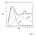
- Fig. 6 shows an example of the course of the in arbitrary units Amount of light S emitted at the receiving element 9 of the sensor according to FIG. 1 is obtained and from the reflection or remission of an object 27 in different sections of the surveillance area.
- the diagram shown is the distance D of in the horizontal direction Object 27 drawn in by the sensor in millimeters.
- the course of the amount of light S 'by imaging the object 27 originating light on the receiving element 9 by means of the only effective zone for the surveillance close range is short shown in dashed lines.
- the long dashed curve shows the amount of light S ", which are the only ones effective for the surveillance extreme close range Zone is mapped to the receiving element 9.
- the solid Line represents the total amount of light S "'that of all three zones the multifocus lens 4 is imaged on the receiving element 9.
- the amount of light S "' is the sum of the amounts of light S', S" and not individually shown amount of light that comes exclusively from the remote monitoring area assigned zone mapped to the receiving element 9 becomes.
- objects 27 are also in the surveillance close range or extremely close range a quantity of light similar to that which for objects 27 in the remote monitoring area at the receiving element 9 is obtained, mapped on this.
- the surveillance area is around the short-range section and the extreme short-range section extended towards the sensor. Only falls directly in front of the sensor the signal with a reduced distance D decreases sharply.
- the design of the multifocus lens 4 can be advantageously simple Be optimized.
- the light entry side 20 of the multifocus lens 4 has all zones common aspherical surface, the curvature of which for illustration of an object 27 within different sections of the surveillance area is optimized for the receiving element 9. Since it is the light entry side 20 around the only curved surface of the multifocus lens 4 acts, their production is very simple.
- the side of the lens In general, it is preferred if the side of the lens, the surface of which is a has a curved shape, has a differentiable course, in particular in cross section along a plane within which the transmission beam runs. This takes place on the corresponding side of the multifocus lens 4 no abrupt change in thickness of the multifocus lens 4, but it has a uniformly smooth surface, making it less is susceptible to contamination.
- the manufacture of the multifocus lens 4 is simplified if a zone of Multifocus lens 4, which in particular has a differentiable course opposite side, is formed as a flat surface.
- a zone of Multifocus lens 4 of the sensor according to FIG. 1 is the light exit side 21 of all zones each designed as a flat surface 22, 23, 24.
- the light exit side of at least one zone be curved, in particular aspherical or spherical surface to be formed enable further optimization of the imaging properties of this zone.
- two zones consists of, in particular, each as a plane surface 22, 23, 24 formed light exit side 21 with respect to one direction to be arranged parallel to the transmission axis 3 spatially offset from one another.
- the optical axis runs for the imaging of a Monitoring remote range provided on the receiving element 9 Zone on the light exit side 21 essentially parallel to the transmission axis 3rd
- the illustration of a surveillance close range or extremely close range the receiving element 9 takes place in the sensor according to FIG. 1 in an advantageously simple manner by the optical axis of the corresponding Zones 23 and 24 of the multifocus lens 4 on the light exit side 21 run at a non-zero angle to the transmission axis.
- the opening area of the light entry side 20 is the one for imaging the Monitoring remote area effective zone of the sensor according to FIG. 1 is significantly larger than the light entry sides 20 for the illustration of a surveillance close range or extremely close range effective Zones of the multifocus lens 4, these zones are each in a similar Solid angle acted upon by the light emitted by objects 27 is reflected in the different surveillance area sections.
- FIG. 6 approximately independent of the distance of the object 27 from the sensor a sufficient amount of light be mapped to the receiving element 9, so that its Sensitivity to this amount of light can be adjusted.
- the Invention also plane surfaces on the light entry side and at least one curved surface can be provided on the light exit side.
Abstract
Description
Die Erfindung betrifft einen opto-elektronischen Sensor zur Überwachung eines Raumbereichs, insbesondere einen Reflexionslichttaster, mit einem Sender zum Aussenden eines Sendelichtstrahls entlang einer Sendeachse, mit einer Empfangsoptik und mit einem Empfangselement.The invention relates to an opto-electronic sensor for monitoring a room area, in particular a reflection light sensor, with a Transmitter for emitting a transmission light beam along a transmission axis, with a receiving optics and with a receiving element.
Solche Sensoren dienen zum Detektieren diffus reflektierender oder remittierender Objekte in einem einen Abschnitt des Sendelichtstrahls umgebenden Überwachungsbereich. Falls ein im Überwachungsbereich befindliches Objekt einen Teil des Sendelichts in Richtung der Empfangsoptik reflektiert, wird dieser zum Empfangselement gelenkt, so daß dieses ein entsprechendes Empfangssignal erzeugt.Such sensors are used to detect diffusely reflecting or remitting Objects in a region surrounding a section of the transmitted light beam Surveillance area. If one in the surveillance area Object part of the transmitted light in the direction of the receiving optics reflected, this is directed to the receiving element, so that this generates a corresponding received signal.
Nachteilig an bekannten derartigen Sensoren ist die räumliche Begrenzung ihres Überwachungsbereichs: Entsprechend den Abbildungseigenschaften der Empfangsoptik werden Objekte lediglich entlang eines eingeschränkten Bereichs der Sendeachse erkannt. Bei Sensoren mit Pupillenteilung ergibt sich das Problem, daß das von nahe am Sensor auf der Sendeachse angeordneten Objekten reflektierte oder remittierte Licht das Empfangselement nicht mehr erreicht.The spatial limitation is a disadvantage of known sensors of this type your surveillance area: According to the imaging properties In the receiving optics, objects are only along a restricted path Range of the transmission axis detected. For sensors with pupil division the problem arises that this is from close to the sensor on the transmit axis arranged objects reflected or reflected light Receiving element no longer reached.
Es ist eine Aufgabe der Erfindung, einen Sensor der eingangs genannten Art zu schaffen, der bei einfacher baulicher Ausgestaltung eine Erweiterung des Überwachungsbereichs in Richtung der Empfangsoptik ermöglicht.It is an object of the invention to provide a sensor of the type mentioned Art to create an extension with a simple structural design of the monitoring area in the direction of the receiving optics.
Erfindungsgemäß wird die Aufgabe dadurch gelöst, daß die Empfangsoptik zur Vergrößerung des Überwachungsbereichs eine Multifokuslinse mit mehreren Zonen unterschiedlicher Brennpunkte aufweist, wobei diejenige Zone, die für die Abbildung eines Überwachungs-Nahbereichs auf das Empfangselement wirksam ist, einen geringeren Abstand zu der Sendeachse aufweist als diejenige Zone, die für die Abbildung eines Überwachungs-Fernbereichs auf das Empfangselement wirksam ist, und wobei die Multifokuslinse asymmetrisch ist.According to the invention the object is achieved in that the receiving optics to enlarge the surveillance area with a multifocus lens has several zones of different focal points, the one Zone that is used for the mapping of a surveillance close range to the Receiving element is effective, a smaller distance from the transmission axis has as that zone which is used for the imaging of a surveillance remote area is effective on the receiving element, and wherein the multifocus lens is asymmetrical.
Indem eine Zone der Multifokuslinse für einen Abschnitt des Überwachungsbereichs wirksam ist, wird das Licht, das von einem in diesem Abschnitt befindlichen Objekt reflektiert oder remittiert wird und die Zone beaufschlagt, von dieser zumindest größtenteils auf das Empfangselement umgelenkt.By a zone of the multifocus lens for a portion of the surveillance area is effective, the light from one in this section object is reflected or remitted and the zone acted upon by this at least largely on the receiving element redirected.
Die erfindungsgemäße asymmetrische Multifokuslinse besitzt insbesondere keine Rotationssymmetrie bezüglich der Sendeachse sowie keine Spiegelsymmetrie bezüglich einer Ebene, welche senkrecht auf der Sendeachse steht. Hingegen gilt noch eine solche Multifokuslinse als erfindungsgemäß, welche spiegelsymmetrisch ist bezüglich einer Ebene, die parallel zu der Sendeachse verläuft oder diese enthält.The asymmetrical multifocus lens according to the invention has in particular no rotational symmetry with respect to the transmission axis and no mirror symmetry with respect to a plane that is perpendicular to the transmission axis stands. On the other hand, such a multifocus lens is still considered to be according to the invention, which is mirror symmetric with respect to a plane parallel to the transmission axis runs or contains it.
Durch die erfindungsgemäße Ausgestaltung der Empfangsoptik mit mehreren, räumlich voneinander getrennten Brennpunkten wird der Überwachungsbereich wirksam erweitert. Durch den asymmetrischen Aufbau der Multifokuslinse läßt sich die Ausgestaltung mit Zonen unterschiedlicher Brennpunkte im Gegensatz zu beispielsweise rotationssymmetrischen Multifokuslinsen besonders einfach realisieren.The inventive design of the receiving optics with several the monitoring area becomes spatially separated focal points effectively expanded. Due to the asymmetrical structure of the Multifocus lens can be designed with different zones Focal points in contrast to, for example, rotationally symmetrical Realize multifocus lenses particularly easily.
Indem die für die Abbildung eines Überwachungs-Nahbereichs wirksame Zone der Multifokuslinse einen vergleichsweise geringen Abstand zu der Sendeachse aufweist, kann der Überwachungsbereich vorteilhaft besonders wirksam in Richtung des Sensors erweitert werden. Das Licht fällt von dem reflektierenden Objekt nämlich in einem geringen Winkel relativ zur Sendeachse auf diese Zone, so daß bei variierendem Abstand des Objekts eine starke Veränderung des Umlenkungswinkels und somit eine Verringerung der das Empfangselement beaufschlagenden Lichtmenge wirksam vermindert wird. Durch den asymmetrischen Aufbau der Multifokuslinse läßt sich ein geringer Abstand zwischen dem Sendestrahl und der für die Abbildung eines Überwachungs-Nahbereichs wirksamen Zone zur Unterdrückung des Effekts der verringerten Lichtbeaufschlagung auf besonders einfache Weise realisieren.By using the effective for imaging a surveillance close range Zone of the multifocus lens a comparatively short distance from the Has monitoring axis, the monitoring area can advantageously be particularly advantageous can be expanded effectively in the direction of the sensor. The light falls of the reflecting object namely at a small angle relative to the transmission axis on this zone, so that with varying distance of the object a strong change in the deflection angle and thus a Reduction in the amount of light acting on the receiving element is effectively reduced. Due to the asymmetrical structure of the multifocus lens can be a small distance between the transmission beam and the zone effective for the imaging of a surveillance close range to suppress the effect of reduced light exposure realize particularly simple way.
Der erfindungsgemäße Sensor wird in Pupillenteilung aufgebaut, also mit voneinander verschiedener Sende- und Empfangsachse, unter Wahrnehmung der mit diesem Aufbau einhergehenden Vorteile, wie beispielsweise dem Ausschließen optischen Übersprechens durch interne Reflexionen und/oder durch Rückstreuungen, die durch Verschmutzung an den optischen Grenzflächen verursacht sind. Im Vergleich mit bekannten Sensoren in Pupillenteilung besitzt der erfindungsgemäße Sensor den Vorteil einer insbesondere in Richtung der Empfangsoptik erfolgten Erweiterung des Überwachungsbereichs. The sensor according to the invention is constructed in pupil division, that is, with different transmission and reception axis, under perception the advantages associated with this structure, such as the exclusion of optical crosstalk through internal reflections and / or by backscattering caused by contamination of the optical Interfaces are caused. In comparison with known sensors in pupil division, the sensor according to the invention has the advantage an expansion that has taken place in particular in the direction of the reception optics of the surveillance area.
Die Erfindung ermöglicht es ferner, die Zonen der Multifokuslinse bzw. deren Brennpunkte derart vorzusehen, daß räumlich im wesentlichen voneinander beabstandete Abschnitte des Überwachungsbereichs entstehen.The invention further enables the zones of the multifocus lens or to provide their focal points in such a way that spatially essentially mutually spaced sections of the monitoring area arise.
In einer bevorzugten Ausführungsform der Erfindung ist die Multifokuslinse einstückig ausgebildet. Vorzugsweise besteht sie aus einem einzigen, im wesentlichen homogenen Material. Eine derartige Ausgestaltung der Multifokuslinse ermöglicht eine besonders einfache Herstellung und Handhabung derselben.In a preferred embodiment of the invention, the multifocus lens integrally formed. It preferably consists of a single, essentially homogeneous material. Such a configuration of the Multifocus lens enables a particularly simple manufacture and Handling the same.
Insbesondere kann die Multifokuslinse aus einem Material von homogenem Brechungsindex gefertigt sein, wobei die verschiedenen Zonen mit ihren durch die jeweilige Oberflächengestaltung und Dicke realisierten unterschiedlichen Abbildungseigenschaften im wesentlichen deutlich von einander abgegrenzt sind.In particular, the multifocus lens can be made from a material of homogeneous Refractive index be made, the different zones with their realized by the respective surface design and thickness differing imaging properties substantially from are delimited from each other.
Alternativ hierzu ist es möglich, die Multifokuslinse als Verlaufslinse auszubilden. In diesem Fall findet ein kontinuierlicher Übergang der Abbildungseigenschaften von einer Zone zur anderen Zone statt.As an alternative to this, it is possible to design the multifocus lens as a gradient lens. In this case there is a continuous transition of the imaging properties from one zone to another zone.
Wenn der Sender in einem nicht sichtbaren Wellenlängenbereich sendet, beispielsweise im Infraroten, ist es bevorzugt, wenn der erfindungsgemäße Sensor einen Pilotsender besitzt, beispielsweise eine rote LED, zum Aussenden eines sichtbaren Pilotlichtstrahls im wesentlichen parallel zu der Sendeachse des Senders. Dadurch kann der Sensor bzw. dessen Überwachungsbereich auf einfache Weise justiert werden. Die erfindungsgemäße Ausgestaltung des Sensors mit einer asymmetrischen Multifokuslinse erleichtert die Integration eines derartigen Pilotsenders in den Sensor, wobei der Pilotlichtstrahl mit einfachsten optischen Mitteln sehr nahe an der Sendeachse geführt werden kann.If the transmitter is transmitting in an invisible wavelength range, for example in the infrared, it is preferred if the invention Sensor has a pilot transmitter, for example a red LED, for transmission of a visible pilot light beam substantially parallel to that Transmitter axis of the transmitter. This enables the sensor or its monitoring area can be adjusted easily. The invention Design of the sensor with an asymmetrical multifocus lens facilitated the integration of such a pilot transmitter in the sensor, wherein the pilot light beam with the simplest optical means very close to the Transmission axis can be guided.
In einer weiteren bevorzugten Ausführungsform besitzt der Sensor eine Meßeinrichtung, beispielsweise eine Lichtlaufzeit-Meßeinrichtung, zur Bestimmung des Abstands eines Objekts innerhalb des Überwachungsbereichs vom Sensor.In a further preferred embodiment, the sensor has one Measuring device, for example a time-of-flight measuring device, for determination the distance of an object within the surveillance area from the sensor.
Weitere bevorzugte Ausführungsformen der Erfindung, insbesondere mögliche Ausgestaltungen der Multifokuslinse, sind in den Unteransprüchen beschrieben.Further preferred embodiments of the invention, in particular possible ones Refinements of the multifocus lens are in the subclaims described.
Die Erfindung wird nachfolgend anhand von Ausführungsbeispielen unter Bezugnahme auf die Zeichnungen beschrieben; in diesen zeigen:
- Fig. 1
- eine perspektivische Seitenansicht von Teilen eines erfindungsgemäßen Sensors,
- Fig. 2a und 2b
- perspektivische Ansichten der Lichtaustrittsseite bzw. Lichteintrittsseite der Multifokuslinse des Sensors gemäß Fig. 1,
- Fig. 2c
- eine Ansicht der Unterseite der Multifokuslinse des Sensors gemäß Fig. 1,
- Fig. 3a und 3b
- eine schematische Seitenansicht bzw. Draufsicht des optischen Systems des Sensors gemäß Fig. 1 mit einem Objekt in einem Überwachungs-Fernbereich,
- Fig. 4a und 4b
- eine schematische Seitenansicht bzw. Draufsicht des optischen Systems des Sensors gemäß Fig. 1 mit einem Objekt in einem Überwachungs-Nahbereich,
- Fig. 5a und 5b
- eine schematische Seitenansicht bzw. Draufsicht des optischen Systems des Sensors gemäß Fig. 1 mit einem Objekt in einem Überwachungs-Extremnahbereich, und
- Fig. 6
- ein Schaubild des Verlaufs der Lichtmenge, die bei einem erfindungsgemäßen Sensor von einem Objekt reflektiert oder remittiert und am Empfangselement erhalten wird, in Abhängigkeit vom Abstand dieses Objekts.
- Fig. 1
- a perspective side view of parts of a sensor according to the invention,
- 2a and 2b
- perspective views of the light exit side or light entry side of the multifocus lens of the sensor according to FIG. 1,
- Fig. 2c
- 2 shows a view of the underside of the multifocus lens of the sensor according to FIG. 1,
- 3a and 3b
- 2 shows a schematic side view or top view of the optical system of the sensor according to FIG. 1 with an object in a remote monitoring area
- 4a and 4b
- 2 shows a schematic side view or top view of the optical system of the sensor according to FIG. 1 with an object in a monitoring close range
- 5a and 5b
- 2 shows a schematic side view or top view of the optical system of the sensor according to FIG. 1 with an object in a monitoring extreme close range, and
- Fig. 6
- a diagram of the course of the amount of light which is reflected or remitted by an object in a sensor according to the invention and is obtained at the receiving element, depending on the distance of this object.
Fig. 1 zeigt schematisch eine perspektivische Seitenansicht von Teilen eines
erfindungsgemäßen Sensors. Der Sensor besitzt eine Infrarot-Laserdiode
als Sender 1 mit aufgesetzter Kollimatorlinseneinheit 2 zum Aussenden
eines Sendelichtstrahls entlang einer Sendeachse 3.Fig. 1 shows schematically a perspective side view of parts of a
sensor according to the invention. The sensor has an infrared laser diode
as
Eine asymmetrisch geformte Empfangs-Multifokuslinse 4, die im wesentlichen
eine in Fig. 1 vertikal nach oben weisende Haupterstreckungsrichtung
5 aufweist, besitzt an ihrem der Sendeachse 3 zugewandten Ende
eine halbzylinderförmige Aussparung 6. Entlang dieser Aussparung 6 umgreift
die Multifokuslinse 4 die Kollimatorlinseneinheit 2 dergestalt, daß
ihre Haupterstreckungsrichtung 5 im wesentlichen senkrecht steht zu der
Sendeachse 3. Die genaue bauliche Ausgestaltung der Multifokuslinse 4
wird nachfolgend anhand der Figuren 2a bis 2c näher erläutert.An asymmetrically shaped
Bezüglich der Senderichtung des Senders 1 von der Multifokuslinse 4 zurückversetzt
befindet sich eine halbkugelförmige Empfangssammellinse 7,
an deren Rückseite ein von einem zylinderförmigen Linsenfortsatz 8 umgebenes
Empfangselement 9 angeordnet ist.Relocated with respect to the direction of transmission of the
Desweiteren ist an der der Multifokuslinse 4 gegenüberliegenden Seite des
Senders 1 eine Pilotsender-Leuchtdiode 10 mit einer Pilotstrahllinse 11
angeordnet zum Aussenden eines Pilotlichtstrahls entlang einer Pilotstrahlsendeachse
12, die im wesentlichen parallel zur Sendeachse 3 verläuft.
In Senderichtung der Pilotstrahllinse 11 und der Multifokuslinse 4
befindet sich eine flächige Schutzscheibe 13.Furthermore, on the opposite side of the
Die vorstehend beschriebenen Bestandteile des Sensors sind durch in
Fig. 1 nicht dargestellte Mittel in ihrer Lage relativ zueinander innerhalb
eines Gehäuses fixiert, dessen Frontseite teilweise durch die Schutzscheibe
13 gebildet ist.The components of the sensor described above are by in
Fig. 1 means not shown in their position relative to each other within
of a housing, the front of which is partially covered by the
Der in Fig. 1 dargestellte Sensor dient als Reflexionslichttaster zum Detektieren
von Objekten innerhalb eines Überwachungsbereichs, der sich
im wesentlichen mit einer durch die Abbildung des Sendelichtstrahls
durch die Kollimatorlinseneinheit 2 vorgegebenen seitlichen Ausdehnung
entlang der Sendeachse 3 erstreckt. Falls ein Objekt von dem Licht des
Senders 1 erfaßt wird, reflektiert es dieses diffus auch in Richtung der
Multifokuslinse 4. Durch deren verschiedene Zonen wird das reflektierte
Licht in Abhängigkeit vom Abstand des Objekts vom Sensor jeweils auf die
Empfangssammellinse 7 und von dieser auf das Empfangselement 9 umgelenkt.
Dieses erzeugt in Abhängigkeit von der empfangenen Lichtintensität
ein Ausgangssignal, das beispielsweise zum Vergleich mit einem
Schwellwert an eine in Fig. 1 nicht dargestellte Auswerteeinheit weitergeleitet
werden kann. Die Wirkungsweise der verschiedenen Zonen der Multifokuslinse
4 wird nachfolgend anhand der Figuren 3a bis 5b erläutert.The sensor shown in Fig. 1 serves as a reflection light scanner for detection
of objects within a surveillance area that are
essentially with one by imaging the transmitted light beam
by the
Die Empfangssammellinse 7 besitzt eine kurze Brennweite und ist unmittelbar
vor dem Empfangselement 9 angeordnet. Ihre halbkugelförmige
Lichteintrittsseite weist eine Öffnungsfläche auf, die wesentlich größer ist
als die lichtempfindliche Fläche des Empfangselements 9, beispielsweise
um einen Faktor 10 bis 100. Dadurch wird die Größe der photoempfindlichen
Fläche virtuell erhöht bzw. kann die lichtempfindliche Fläche des
Empfangselements 9 zur Erzielung eines geringen elektronischen Rauschens
reell gering gehalten werden. Außerdem ermöglicht die Empfangssammellinse
7 die Kompensation von Justagefehlern zwischen der Sendeachse
3 und den optischen Achsen der Lichtaustrittsseiten 22, 23, 24 der
verschiedenen Zonen der Multifokuslinse 4 bis zu ± 3°, und sie erlaubt
somit eine einfachere und schnellere Montage des Sensors. Durch die
Verwendung der Empfangssammellinse 7 läßt sich ferner eine geringere
Bautiefe des Sensors erreichen.The receiving
Der Pilotsender 10, 11 sendet einen sichtbaren Pilotlichtstrahl entlang der
Achse 12 aus, der das Justieren des Senders 1 und somit des Sensors
vereinfacht. The
Die Figuren 2a, 2b und 2c zeigen perspektivische Seitenansichten bzw.
eine Ansicht der Unterseite der Multifokuslinse 4 des Sensors gemäß
Fig. 1. Die Multifokuslinse 4 besitzt eine Lichteintrittsseite 20 mit einer
einzigen asphärischen Oberfläche. Eine der Lichteintrittsseite 20 gegenüberliegende
Lichtaustrittsseite 21 der Multifokuslinse 4 weist drei Planflächen
22, 23, 24 auf, welche jeweils einer für die Abbildung eines bestimmten
Abschnitts des Überwachungsbereichs wirksamen Zone zugeordnet
sind.Figures 2a, 2b and 2c show perspective side views and
a view of the underside of the
Die Planfläche 22 der für die Abbildung eines Überwachungs-Fernbereichs
wirksamen Zone nimmt den überwiegenden Teil der Lichtaustrittsseite 21
ein. Diese Fern-Planfläche 22 erstreckt sich innerhalb einer Ebene im wesentlichen
senkrecht zu der Sendeachse 3 ungefähr bis auf die Höhe der
Aussparung 6. An diesem Ende der Planfläche 22 schließen sich die beiden
Planflächen 23, 24 an, welche diejenigen Zonen der Multifokuslinse 4
seitlich begrenzen, die für die Abbildung eines Überwachungs-Nahbereichs
bzw. -Extremnahbereichs wirksam sind.The
Die beiden Planflächen 23, 24 erstrecken sich im wesentlichen jeweils an
einer Seite der Aussparung 6 von dem Ende der Fern-Planfläche 22 entgegen
der Haupterstreckungsrichtung 5 bis auf die Höhe der Sendeachse 3.
Die Flächennormale der Nah-Planfläche 23 steht in einem Winkel von etwa
91° zu der Haupterstreckungsrichtung 5 und schließt mit der Sendeachse
3 einen Winkel von ungefähr 5° ein. Die Flächennormale der Extremnah-Planfläche
24 schließt mit der Haupterstreckungsrichtung 5 einen
Winkel von etwa 91,5° und mit der Sendeachse 3 einen Winkel von
ungefähr 11° ein. Die jeweils der Fern-Planfläche 22 benachbarte Kante
der Nah-Planfläche 23 und der Extremnah-Planfläche 24 ist in Richtung
der Lichteintrittsseite 20 der Multifokuslinse 4 zurückversetzt.The two
Die drei Planflächen 22, 23, 24 sind seitlich jeweils durch eine parallel
sowohl zu der Sendeachse 3 als auch der Haupterstreckungsrichtung 5
verlaufende plane Seitenfläche 25 bzw. 26 begrenzt.The three
Fig. 2c zeigt die Unterseite der Multifokuslinse 4 in einer Ansicht in
Haupterstreckungsrichtung 5. Die Unterseite der für die Abbildung eines
Nahbereichs bzw. eines Extremnahbereichs wirksamen Zone besitzt jeweils
ungefähr den Umriß eines Trapezes, dessen an die Lichteintrittsseite
20 der Multifokuslinse 4 angrenzende Seite gekrümmt ist entsprechend
dem asphärischen Verlauf der Oberfläche 20. In der Ansicht gemäß Fig.
2c ist auch die Verkippung der Nah- und Extremnah-Planfläche 23 bzw.
24 bezüglich der Haupterstreckungsrichtung 5 zu erkennen. Die Neigungen
der Planflächen 23, 24 bezüglich der Sendeachse 3 bzw. der Haupterstreckungsrichtung
5 können auch anders gewählt sein, je nach den gewünschten
Abbildungseigenschaften der entsprechenden Zonen.2c shows the underside of the
Die Figuren 3a und 3b, 4a und 4b, sowie 5a und 5b zeigen jeweils in
schematisierter Seitenansicht bzw. Draufsicht das optische System des
Sensors gemäß der Fig. 1 und illustrieren durch die eingezeichnete
Schraffur die Abbildung von reflektiertem oder remittiertem Licht eines
Objekts 27, das sich jeweils in großer Entfernung vom Sensor bzw. nahe
dem Sensor bzw. in unmittelbarer Nähe des Sensors befindet, auf das
Empfangselement 9 des Sensors mittels der jeweils wirksamen Zone der
Multifokuslinse 4. Figures 3a and 3b, 4a and 4b, and 5a and 5b each show in
schematic side view or top view of the optical system of the
1 and illustrate by the drawn in
Hatching the image of reflected or reflected light from a
In der Darstellung gemäß den Figuren 3a und 3b befindet sich das Objekt
27 in einem Überwachungs-Fernbereich. Die für die Abbildung dieses
Objekts 27 auf die Empfangssammellinse 7 bzw. das Empfangselement 9
wirksame Zone der Multifokuslinse 4 umfaßt insbesondere denjenigen Bereich
der Multifokuslinse 4, der sich von der Planfläche 22 an der Lichtaustrittsseite
21 in Richtung der Sendeachse 3 bis zu der Lichteintrittsseite
20 der Multifokuslinse 4 erstreckt.The object is in the representation according to FIGS. 3a and
Wie aus den Figuren 4a und 4b hervorgeht, ist die für die Abbildung eines
in einem Überwachungs-Nahbereich befindlichen Objekts 27 wirksame
Zone der Multifokuslinse 4 durch denjenigen Bereich gebildet, der sich
von der Planfläche 23 parallel zu der Sendeachse bis zu der Lichteintrittsseite
20 der Multifokuslinse 4 erstreckt. Entsprechend der Darstellung in
Draufsicht gemäß Fig. 4b befindet sich diese Zone lediglich innerhalb einer
Seitenhälfte der Multifokuslinse 4.As can be seen from FIGS. 4a and 4b, the one for imaging is a
Dementsprechend geht aus den Figuren 5a und 5b hervor, daß das Reflexions-
oder Remissionslicht eines in einem Überwachungs-Extremnahbereich
befindlichen Objekts 27 mittels der sich von der Planfläche 24 bis zu
der Lichteintrittsseite 20 der Multifokuslinse 4 erstreckenden Zone sowie
mittels der Empfangssammellinse 7 auf das Empfangselement 9 abgebildet
wird.Accordingly, it can be seen from FIGS. 5a and 5b that the reflection
or remission light in a surveillance extreme close range
located
Aus den Figuren 3a bis 5b geht somit hervor, daß die Ausgestaltung der
Multifokuslinse 4 mit verschiedenen Zonen mit unterschiedlichen, räumlich
voneinander getrennten Brennpunkten auf einfache Weise eine vorteilhafte
Erweiterung des Überwachungsbereichs entlang der Sendeachse
3 ermöglicht. Objekte 27 in verschiedenen Abschnitten des Überwachungsbereichs
werden dabei nicht unbedingt ausschließlich mittels der
jeweils entsprechenden, vorstehend als wirksam bezeichneten Zone auf
das Empfangselement 9 abgebildet; im Übergangsbereich zwischen benachbarten
derartigen Abschnitten des Überwachungsbereichs erfolgt die
Abbildung des von einem Objekt 27 reflektierten Lichts auf das Empfangselement
9 des Sensor gegebenenfalls mittels der beiden den benachbarten
Überwachungsbereich-Abschnitten entsprechenden Zonen. Die verschiedenen
Überwachungsbereich-Abschnitte müssen nicht unbedingt geradlinig
entlang der Sendeachse 3 angeordnet sein, sondern können auch seitlich
versetzt zueinander sein.It can thus be seen from FIGS. 3a to 5b that the configuration of the
Fig. 6 zeigt beispielhaft und in willkürlichen Einheiten den Verlauf der
Lichtmenge S, die an dem Empfangselement 9 des Sensors gemäß Fig. 1
erhalten wird und von der Reflexion oder Remission eines Objekts 27 in
verschiedenen Abschnitten des Überwachungsbereichs stammt. Bei dem
dargestellten Schaubild ist in horizontaler Richtung der Abstand D des
Objekts 27 vom Sensor in der Einheit Millimeter eingezeichnet.Fig. 6 shows an example of the course of the in arbitrary units
Amount of light S emitted at the receiving
Der Verlauf der Lichtmenge S', die durch Abbildung des von dem Objekt
27 stammenden Lichts auf das Empfangselement 9 mittels der lediglich
für den Überwachungs-Nahbereich wirksamen Zone erzeugt wird, ist kurz
gestrichelt wiedergegeben. Die lang gestrichelte Kurve zeigt die Lichtmenge
S", die allein von der für den Überwachungs-Extremnahbereich wirksamen
Zone auf das Empfangselement 9 abgebildet wird. Die durchgezogene
Linie gibt die Gesamtlichtmenge S"' wieder, die von allen drei Zonen
der Multifokuslinse 4 auf das Empfangselement 9 abgebildet wird. Die
Lichtmenge S"' ist also die Summe der Lichtmengen S', S" sowie der nicht
einzeln dargestellten Lichtmenge, die ausschließlich von der dem Überwachungs-Fernbereich
zugeordneten Zone auf das Empfangselement 9 abgebildet
wird.The course of the amount of light S 'by imaging the
Wie aus Fig. 6 hervorgeht, wird auch für Objekte 27 im Überwachungs-Nahbereich
bzw. -Extremnahbereich noch eine Lichtmenge ähnlich jener,
welche für Objekte 27 im Überwachungs-Fernbereich am Empfangselement
9 erhalten wird, auf dieses abgebildet. Der Überwachungsbereich
ist um den Nahbereichs-Abschnitt und den Extremnahbereichs-Abschnitt
in Richtung des Sensors erweitert. Erst unmittelbar vor dem Sensor fällt
das Signal mit verringertem Abstand D stark ab.As can be seen from FIG. 6, objects 27 are also in the surveillance close range
or extremely close range a quantity of light similar to that
which for
Die Ausgestaltung der Multifokuslinse 4 kann auf vorteilhaft einfache
Weise optimiert sein. Wie insbesondere aus den Figuren 1 und 2b hervorgeht,
besitzt die Lichteintrittsseite 20 der Multifokuslinse 4 eine allen Zonen
gemeinsame asphärische Oberfläche, deren Krümmung für die Abbildung
eines Objekts 27 innerhalb verschiedener Abschnitte des Überwachungsbereichs
auf das Empfangselement 9 optimiert ist. Da es sich bei
der Lichteintrittsseite 20 um die einzige gekrümmte Oberfläche der Multifokuslinse
4 handelt, ist deren Herstellung sehr einfach.The design of the
Allgemein ist es bevorzugt, wenn die Seite der Linse, deren Oberfläche eine
gekrümmte Form aufweist, einen differenzierbaren Verlauf besitzt, insbesondere
im Querschnitt entlang einer Ebene, innerhalb welcher der Sendestrahl
verläuft. Somit erfolgt an der entsprechenden Seite der Multifokuslinse
4 keine abrupte Dickenveränderung der Multifokuslinse 4, sondern
sie besitzt eine gleichmäßig glatte Oberfläche, wodurch sie weniger
verschmutzungsanfällig ist. In general, it is preferred if the side of the lens, the surface of which is a
has a curved shape, has a differentiable course, in particular
in cross section along a plane within which the transmission beam
runs. This takes place on the corresponding side of the
Die Herstellung der Multifokuslinse 4 vereinfacht sich, wenn eine Zone der
Multifokuslinse 4, die insbesondere der einen differenzierbaren Verlauf
aufweisenden Seite gegenüberliegt, als Planfläche ausgebildet ist. Im Falle
der Multifokuslinse 4 des Sensors gemäß Fig. 1 ist die Lichtaustrittsseite
21 aller Zonen jeweils als Planfläche 22, 23, 24 gestaltet. Alternativ hierzu
kann die Lichtaustrittsseite zumindest einer Zone als gekrümmte, insbesondere
asphärische oder sphärische Oberfläche ausgebildet sein, um eine
weitere Optimierung der Abbildungseigenschaften dieser Zone zu ermöglichen.The manufacture of the
Eine sehr einfache Möglichkeit zur Variierung der Abbildungseigenschaften
zweier Zonen besteht darin, ihre insbesondere jeweils als Planfläche
22, 23, 24 ausgebildete Lichtaustrittsseite 21 bezüglich einer Richtung
parallel zu der Sendeachse 3 räumlich versetzt zueinander anzuordnen.A very easy way to vary the imaging properties
two zones consists of, in particular, each as a
Gemäß Fig. 1 verläuft die optische Achse der für die Abbildung eines
Überwachungs-Fernbereichs auf das Empfangselement 9 vorgesehenen
Zone auf der Lichtaustrittsseite 21 im wesentlichen parallel zu der Sendeachse
3.1, the optical axis runs for the imaging of a
Monitoring remote range provided on the receiving
Die Abbildung eines Überwachungs-Nahbereichs bzw. -Extremnahbereichs
auf das Empfangselement 9 erfolgt bei dem Sensor gemäß Fig. 1
auf vorteilhaft einfache Weise, indem die optische Achse der entsprechenden
Zonen 23 bzw. 24 der Multifokuslinse 4 auf der Lichtaustrittsseite 21
in einem von Null verschiedenen Winkel zur Sendeachse verlaufen.The illustration of a surveillance close range or extremely close range
the receiving
Da die Öffnungsfläche der Lichteintrittsseite 20 der für die Abbildung des
Überwachungs-Fernbereichs wirksamen Zone des Sensors gemäß Fig. 1
erheblich größer ist als die Lichteintrittsseiten 20 der für die Abbildung
eines Überwachungs-Nahbereichs bzw. -Extremnahbereichs wirksamen
Zonen der Multifokuslinse 4, werden diese Zonen jeweils in einem ähnlichen
Raumwinkel von dem Licht beaufschlagt, welches von Objekten 27
in den verschiedenen Überwachungsbereich-Abschnitten reflektiert wird.
Somit kann - wie aus Fig. 6 ersichtlich - näherungsweise unabhängig von
dem Abstand des Objekts 27 von dem Sensor eine ausreichende Lichtmenge
auf das Empfangselement 9 abgebildet werden, so daß dessen
Empfindlichkeit an diese Lichtmenge angepaßt werden kann.Since the opening area of the
Schließlich sei bemerkt, daß bei einer alternativen Ausführungsform der Erfindung auch Planflächen auf der Lichteintrittsseite und zumindest eine gekrümmte Fläche auf der Lichtaustrittsseite vorgesehen werden können. Finally, it should be noted that in an alternative embodiment the Invention also plane surfaces on the light entry side and at least one curved surface can be provided on the light exit side.
- 11
- SenderChannel
- 22nd
- KollimatorlinseneinheitCollimator lens unit
- 33rd
- SendeachseTransmission axis
- 44th
- MultifokuslinseMultifocus lens
- 55
- HaupterstreckungsrichtungMain direction of extension
- 66
- AussparungRecess
- 77
- EmpfangssammellinseReception lens
- 88th
- LinsenfortsatzLenticular process
- 99
- EmpfangselementReceiving element
- 1010th
- PilotleuchtdiodePilot light emitting diode
- 1111
- PilotstrahllinsePilot beam lens
- 1212th
- PilotstrahlsendeachsePilot beam transmission axis
- 1313
- SchutzscheibeProtective screen
- 2020th
- LichteintrittsseiteLight entry side
- 2121
- LichtaustrittsseiteLight exit side
- 2222
- PlanflächeFlat area
- 2323
- PlanflächeFlat area
- 2424th
- PlanflächeFlat area
- 2525th
- SeitenflächeSide surface
- 2626
- SeitenflächeSide surface
- 2727
- Objektobject
- SS
- LichtmengeAmount of light
- S'S '
- Lichtmenge der dem Überwachungs-Nahbereich zugeordneten ZoneLight quantity of the zone assigned to the surveillance close range
- S"S "
- Lichtmenge der dem Überwachungs-Extremnahbereich zugeordneten ZoneAmount of light assigned to the extreme surveillance area Zone
- S"'S "'
- Lichtmenge aller ZonenAmount of light from all zones
- DD
- Abstanddistance
Claims (10)
dadurch gekennzeichnet,
characterized by
dadurch gekennzeichnet,
daß die Lichteintrittsseite (20) oder die Lichtaustrittsseite (21) der Multifokuslinse (4) im Querschnitt entlang einer Ebene, innerhalb welcher der Sende strahl verläuft, einen differenzierbaren Verlauf aufweist und/oder daß die Lichteintrittsseite (20) oder die Lichtaustrittsseite (21) der Multifokuslinse (4) eine allen Zonen gemeinsame asphärische Oberfläche aufweist.Optoelectronic sensor according to claim 1,
characterized by
that the light entry side (20) or the light exit side (21) of the multifocus lens (4) has a differentiable profile in cross section along a plane within which the transmission beam runs and / or that the light entry side (20) or the light exit side (21) of the Multifocus lens (4) has an aspherical surface common to all zones.
daß die Lichteintrittsseiten oder die Lichtaustrittsseiten (23, 24) zweier Zonen der Multifokuslinse (4) bezüglich einer Richtung parallel zu der Sendeachse (3) räumlich versetzt zueinander angeordnet sind und/oder daß die optische Achse wenigstens einer Zone der Multifokuslinse (4), insbesondere einer für die Abbildung eines Überwachungs-Fernbereichs auf das Empfangselement (9) vorgesehenen Zone, auf der Lichtaustrittsseite (22) zumindest im wesentlichen parallel zu der Sendeachse (3) verläuft.Optoelectronic sensor according to one of the preceding claims, characterized in that
that the light entry sides or the light exit sides (23, 24) of two zones of the multifocus lens (4) are spatially offset from one another with respect to a direction parallel to the transmission axis (3) and / or that the optical axis of at least one zone of the multifocus lens (4), in particular a zone provided for mapping a remote monitoring area onto the receiving element (9), on the light exit side (22) at least substantially parallel to the transmission axis (3).
daß die optische Achse wenigstens einer Zone der Multifokuslinse (4), insbesondere einer für die Abbildung eines Überwachungs-Nahbereichs auf das Empfangselement (9) vorgesehenen Zone, auf der Lichtaustrittsseite (23, 24) in einem von Null verschiedenen Winkel zur Sendeachse (3) verläuft und/oder daß die Multifokuslinse (4) einstückig ist und/oder aus einem einzigen, im wesentlichen homogenen Material ausgebildet ist und/oder einen homogenen Brechungsindex aufweist. Optoelectronic sensor according to one of the preceding claims, characterized in that
that the optical axis of at least one zone of the multifocus lens (4), in particular a zone provided for imaging a close-up surveillance region on the receiving element (9), on the light exit side (23, 24) at an angle different from zero to the transmission axis (3) runs and / or that the multifocus lens (4) is in one piece and / or is formed from a single, essentially homogeneous material and / or has a homogeneous refractive index.
daß die Zonen der Multifokuslinse (4) bezüglich ihrer jeweiligen Abbildungseigenschaften im wesentlichen deutlich voneinander abgegrenzt sind, oder daß die Multifokuslinse (4) als Verlaufslinse ausgebildet ist mit einem kontinuierlichen Übergang der Abbildungseigenschaften von einer Zone zur anderen Zone.Optoelectronic sensor according to one of the preceding claims, characterized in that
that the zones of the multifocus lens (4) are essentially clearly delimited from one another with regard to their respective imaging properties, or that the multifocus lens (4) is designed as a gradient lens with a continuous transition of the imaging properties from one zone to the other zone.
daß die Empfangsoptik zusätzlich eine Empfangssammellinse (7) kurzer Brennweite aufweist, die unmittelbar vor dem Empfangselement (9) angeordnet ist und deren Öffnungsfläche größer ist als die lichtempfindliche Fläche des Empfangselements (9), wobei insbesondere die Öffnungsfläche der Empfangssammellinse (7) um einen Faktor 10 bis 100 größer ist als die lichtempfindliche Fläche des Empfangselements (9).Optoelectronic sensor according to one of the preceding claims, characterized in that
that the receiving optics additionally have a receiving collective lens (7) with a short focal length, which is arranged directly in front of the receiving element (9) and whose opening area is larger than the light-sensitive area of the receiving element (9), in particular the opening area of the receiving collective lens (7) by a factor 10 to 100 is larger than the light-sensitive area of the receiving element (9).
daß er zur Bestimmung des Abstands eines Objekts innerhalb des Überwachungsbereichs vom Sensor eine Meßeinrichtung, insbesondere eine Lichtlaufzeit-Meßeinrichtung, aufweist.Optoelectronic sensor according to one of the preceding claims, characterized in that
that it has a measuring device, in particular a light transit time measuring device, for determining the distance of an object within the monitoring area from the sensor.
Applications Claiming Priority (2)
| Application Number | Priority Date | Filing Date | Title |
|---|---|---|---|
| DE19756541A DE19756541A1 (en) | 1997-12-18 | 1997-12-18 | Opto-electronic sensor |
| DE19756541 | 1997-12-18 |
Publications (3)
| Publication Number | Publication Date |
|---|---|
| EP0924535A2 true EP0924535A2 (en) | 1999-06-23 |
| EP0924535A3 EP0924535A3 (en) | 2000-01-05 |
| EP0924535B1 EP0924535B1 (en) | 2005-02-16 |
Family
ID=7852539
Family Applications (1)
| Application Number | Title | Priority Date | Filing Date |
|---|---|---|---|
| EP98124137A Expired - Lifetime EP0924535B1 (en) | 1997-12-18 | 1998-12-18 | Opto-electronic sensor |
Country Status (2)
| Country | Link |
|---|---|
| EP (1) | EP0924535B1 (en) |
| DE (2) | DE19756541A1 (en) |
Cited By (3)
| Publication number | Priority date | Publication date | Assignee | Title |
|---|---|---|---|---|
| EP2101189A1 (en) | 2008-03-14 | 2009-09-16 | Firma Pepperl + Fuchs GmbH | Optical sensor |
| EP3002609A1 (en) * | 2014-10-01 | 2016-04-06 | Sick Ag | Optoelectronic sensor |
| US9810626B2 (en) | 2015-04-08 | 2017-11-07 | Sick Ag | Optoelectronic sensor and method for the transmission monitoring of a front screen |
Families Citing this family (3)
| Publication number | Priority date | Publication date | Assignee | Title |
|---|---|---|---|---|
| DE10331074A1 (en) * | 2003-07-09 | 2005-02-03 | Conti Temic Microelectronic Gmbh | Sensor arrangement for distance and / or speed measurement |
| DE202021104670U1 (en) | 2021-08-31 | 2022-12-01 | Sick Ag | Photoelectric sensor for detecting objects in a surveillance area |
| DE102021122418A1 (en) | 2021-08-31 | 2023-03-02 | Sick Ag | Photoelectric sensor and method for detecting objects in a surveillance area |
Citations (2)
| Publication number | Priority date | Publication date | Assignee | Title |
|---|---|---|---|---|
| EP0635729A1 (en) * | 1991-09-13 | 1995-01-25 | Nippondenso Co., Ltd. | Optical radar |
| EP0665522A1 (en) * | 1994-01-27 | 1995-08-02 | Security Enclosures Limited | Wide-angle infra-red detection apparatus |
Family Cites Families (7)
| Publication number | Priority date | Publication date | Assignee | Title |
|---|---|---|---|---|
| DE1145365B (en) * | 1959-12-29 | 1963-03-14 | Ernst Befort | Photoelectric scanning device |
| DE1883592U (en) * | 1963-09-07 | 1963-11-28 | Erwin Sick | LIGHT-ELECTRIC SENSING DEVICE. |
| DE1297006C2 (en) * | 1967-12-16 | 1973-12-06 | Endl Alfons | Reflex light barrier |
| DE3214406C1 (en) * | 1982-04-20 | 1983-06-01 | Elektro-Automation Dipl.-Ing. Joachim Pantel, 8520 Erlangen | Lens for a light-controlling device |
| US4880974A (en) * | 1988-10-14 | 1989-11-14 | Wako Corporation | Photoelectric sensor employing custom lens member |
| DE4402642C2 (en) * | 1994-01-29 | 1995-11-23 | Leuze Electronic Gmbh & Co | Optoelectronic device for locating obstacles |
| DE19619308A1 (en) * | 1996-05-13 | 1997-11-20 | Sick Ag | Combination light scanner for detecting objects in monitoring field, e.g. on conveyor |
-
1997
- 1997-12-18 DE DE19756541A patent/DE19756541A1/en not_active Withdrawn
-
1998
- 1998-12-18 EP EP98124137A patent/EP0924535B1/en not_active Expired - Lifetime
- 1998-12-18 DE DE59812575T patent/DE59812575D1/en not_active Expired - Lifetime
Patent Citations (2)
| Publication number | Priority date | Publication date | Assignee | Title |
|---|---|---|---|---|
| EP0635729A1 (en) * | 1991-09-13 | 1995-01-25 | Nippondenso Co., Ltd. | Optical radar |
| EP0665522A1 (en) * | 1994-01-27 | 1995-08-02 | Security Enclosures Limited | Wide-angle infra-red detection apparatus |
Cited By (4)
| Publication number | Priority date | Publication date | Assignee | Title |
|---|---|---|---|---|
| EP2101189A1 (en) | 2008-03-14 | 2009-09-16 | Firma Pepperl + Fuchs GmbH | Optical sensor |
| EP3002609A1 (en) * | 2014-10-01 | 2016-04-06 | Sick Ag | Optoelectronic sensor |
| US9810626B2 (en) | 2015-04-08 | 2017-11-07 | Sick Ag | Optoelectronic sensor and method for the transmission monitoring of a front screen |
| EP3078985B1 (en) * | 2015-04-08 | 2018-03-14 | Sick Ag | Optoelectronic sensor and method for transmission monitoring a windshield |
Also Published As
| Publication number | Publication date |
|---|---|
| DE59812575D1 (en) | 2005-03-24 |
| EP0924535B1 (en) | 2005-02-16 |
| EP0924535A3 (en) | 2000-01-05 |
| DE19756541A1 (en) | 1999-06-24 |
Similar Documents
| Publication | Publication Date | Title |
|---|---|---|
| DE102007036492B4 (en) | Optical sensor device | |
| EP3673290A1 (en) | Transmitting device for a lidar scanner having a scanning mirror covered by a cover element | |
| WO2003002939A1 (en) | Device for optical measurement of distance over a large measuring range | |
| EP2378309B1 (en) | Optoelectronic sensor and method for recording information about objects in a monitoring area | |
| DE102007027429B4 (en) | Radar device and optical receiver for it | |
| DE102005033349A1 (en) | Light barrier monitoring object detection optical sensor has transmitter and receiver with additional transmitter and receiver for second reflected light beam from object | |
| DE102012212150A1 (en) | Laser radar device for use in driver assistance system to detect objects in surroundings of motor vehicle, has receiver, where spatial relationship of radiation or reception range prevents that receiver receives echo from object | |
| EP3168642B1 (en) | Optoelectronic sensor and method for detecting an object | |
| DE19532680A1 (en) | Optical system | |
| DE4431889B4 (en) | Light scattering type smoke sensor | |
| DE102007030880B4 (en) | Device for detecting an object scene | |
| EP3229042B1 (en) | Optoelectronic sensor and method for detecting an object and measuring the distance to it | |
| EP1624322A1 (en) | Optical sensor | |
| DE19860464C2 (en) | Laser distance measuring device for large measuring ranges | |
| EP0924535B1 (en) | Opto-electronic sensor | |
| EP1421430A1 (en) | Scanning device | |
| EP1695109A1 (en) | Device for measuring the distance to far-off objects and close objects | |
| DE4407911C2 (en) | Optical system with a radiation focusing and deflecting optic body | |
| WO2013013872A1 (en) | Optical measuring device for a vehicle | |
| DE102015105263A1 (en) | Optoelectronic sensor and method for detecting objects in a surveillance area | |
| DE3707986C2 (en) | ||
| EP0421119B1 (en) | Passive infrared motion detector | |
| DE102004003386C5 (en) | Optical sensor | |
| EP4118405B1 (en) | Infrared motion detector | |
| DE102015222380B4 (en) | Distance measurement system |
Legal Events
| Date | Code | Title | Description |
|---|---|---|---|
| PUAI | Public reference made under article 153(3) epc to a published international application that has entered the european phase |
Free format text: ORIGINAL CODE: 0009012 |
|
| AK | Designated contracting states |
Kind code of ref document: A2 Designated state(s): CH DE FR IT LI |
|
| AX | Request for extension of the european patent |
Free format text: AL;LT;LV;MK;RO;SI |
|
| PUAL | Search report despatched |
Free format text: ORIGINAL CODE: 0009013 |
|
| AK | Designated contracting states |
Kind code of ref document: A3 Designated state(s): AT BE CH CY DE DK ES FI FR GB GR IE IT LI LU MC NL PT SE |
|
| AX | Request for extension of the european patent |
Free format text: AL;LT;LV;MK;RO;SI |
|
| 17P | Request for examination filed |
Effective date: 20000211 |
|
| AKX | Designation fees paid |
Free format text: CH DE FR IT LI |
|
| GRAP | Despatch of communication of intention to grant a patent |
Free format text: ORIGINAL CODE: EPIDOSNIGR1 |
|
| GRAS | Grant fee paid |
Free format text: ORIGINAL CODE: EPIDOSNIGR3 |
|
| GRAA | (expected) grant |
Free format text: ORIGINAL CODE: 0009210 |
|
| AK | Designated contracting states |
Kind code of ref document: B1 Designated state(s): CH DE FR IT LI |
|
| REG | Reference to a national code |
Ref country code: CH Ref legal event code: EP |
|
| REF | Corresponds to: |
Ref document number: 59812575 Country of ref document: DE Date of ref document: 20050324 Kind code of ref document: P |
|
| PLBE | No opposition filed within time limit |
Free format text: ORIGINAL CODE: 0009261 |
|
| STAA | Information on the status of an ep patent application or granted ep patent |
Free format text: STATUS: NO OPPOSITION FILED WITHIN TIME LIMIT |
|
| ET | Fr: translation filed | ||
| 26N | No opposition filed |
Effective date: 20051117 |
|
| PGFP | Annual fee paid to national office [announced via postgrant information from national office to epo] |
Ref country code: FR Payment date: 20131213 Year of fee payment: 16 |
|
| PGFP | Annual fee paid to national office [announced via postgrant information from national office to epo] |
Ref country code: CH Payment date: 20141216 Year of fee payment: 17 |
|
| REG | Reference to a national code |
Ref country code: FR Ref legal event code: ST Effective date: 20150831 |
|
| PG25 | Lapsed in a contracting state [announced via postgrant information from national office to epo] |
Ref country code: FR Free format text: LAPSE BECAUSE OF NON-PAYMENT OF DUE FEES Effective date: 20141231 |
|
| PGFP | Annual fee paid to national office [announced via postgrant information from national office to epo] |
Ref country code: DE Payment date: 20151217 Year of fee payment: 18 |
|
| REG | Reference to a national code |
Ref country code: CH Ref legal event code: PL |
|
| PGFP | Annual fee paid to national office [announced via postgrant information from national office to epo] |
Ref country code: IT Payment date: 20151222 Year of fee payment: 18 |
|
| PG25 | Lapsed in a contracting state [announced via postgrant information from national office to epo] |
Ref country code: LI Free format text: LAPSE BECAUSE OF NON-PAYMENT OF DUE FEES Effective date: 20151231 Ref country code: CH Free format text: LAPSE BECAUSE OF NON-PAYMENT OF DUE FEES Effective date: 20151231 |
|
| REG | Reference to a national code |
Ref country code: DE Ref legal event code: R119 Ref document number: 59812575 Country of ref document: DE |
|
| PG25 | Lapsed in a contracting state [announced via postgrant information from national office to epo] |
Ref country code: IT Free format text: LAPSE BECAUSE OF NON-PAYMENT OF DUE FEES Effective date: 20161218 |
|
| PG25 | Lapsed in a contracting state [announced via postgrant information from national office to epo] |
Ref country code: DE Free format text: LAPSE BECAUSE OF NON-PAYMENT OF DUE FEES Effective date: 20170701 |