EP0923881A2 - Roll orientor - Google Patents
Roll orientor Download PDFInfo
- Publication number
- EP0923881A2 EP0923881A2 EP99104972A EP99104972A EP0923881A2 EP 0923881 A2 EP0923881 A2 EP 0923881A2 EP 99104972 A EP99104972 A EP 99104972A EP 99104972 A EP99104972 A EP 99104972A EP 0923881 A2 EP0923881 A2 EP 0923881A2
- Authority
- EP
- European Patent Office
- Prior art keywords
- pear
- rolls
- pair
- roll
- pears
- Prior art date
- Legal status (The legal status is an assumption and is not a legal conclusion. Google has not performed a legal analysis and makes no representation as to the accuracy of the status listed.)
- Granted
Links
Images


Classifications
-
- A—HUMAN NECESSITIES
- A23—FOODS OR FOODSTUFFS; TREATMENT THEREOF, NOT COVERED BY OTHER CLASSES
- A23N—MACHINES OR APPARATUS FOR TREATING HARVESTED FRUIT, VEGETABLES OR FLOWER BULBS IN BULK, NOT OTHERWISE PROVIDED FOR; PEELING VEGETABLES OR FRUIT IN BULK; APPARATUS FOR PREPARING ANIMAL FEEDING- STUFFS
- A23N4/00—Machines for stoning fruit or removing seed-containing sections from fruit, characterised by their stoning or removing device
- A23N4/12—Machines for stoning fruit or removing seed-containing sections from fruit, characterised by their stoning or removing device for coring fruit
- A23N4/14—Machines for stoning fruit or removing seed-containing sections from fruit, characterised by their stoning or removing device for coring fruit for apples, pears or the like
-
- A—HUMAN NECESSITIES
- A23—FOODS OR FOODSTUFFS; TREATMENT THEREOF, NOT COVERED BY OTHER CLASSES
- A23N—MACHINES OR APPARATUS FOR TREATING HARVESTED FRUIT, VEGETABLES OR FLOWER BULBS IN BULK, NOT OTHERWISE PROVIDED FOR; PEELING VEGETABLES OR FRUIT IN BULK; APPARATUS FOR PREPARING ANIMAL FEEDING- STUFFS
- A23N7/00—Peeling vegetables or fruit
- A23N7/02—Peeling potatoes, apples or similarly shaped vegetables or fruit
- A23N7/023—Peeling potatoes, apples or similarly shaped vegetables or fruit one by one
- A23N7/026—Peeling machines therefor with rotary fruit holding spindles and fixed or movable peeler blades
-
- Y—GENERAL TAGGING OF NEW TECHNOLOGICAL DEVELOPMENTS; GENERAL TAGGING OF CROSS-SECTIONAL TECHNOLOGIES SPANNING OVER SEVERAL SECTIONS OF THE IPC; TECHNICAL SUBJECTS COVERED BY FORMER USPC CROSS-REFERENCE ART COLLECTIONS [XRACs] AND DIGESTS
- Y10—TECHNICAL SUBJECTS COVERED BY FORMER USPC
- Y10S—TECHNICAL SUBJECTS COVERED BY FORMER USPC CROSS-REFERENCE ART COLLECTIONS [XRACs] AND DIGESTS
- Y10S426/00—Food or edible material: processes, compositions, and products
- Y10S426/809—Food or edible material: processes, compositions, and products including harvesting or planting or other numerous miscellaneous processing steps
Definitions
- This invention relates generally to pear processing machines. More particularly, the invention relates to a method and apparatus for peeling, coring, seed celling and trimming pears of various sizes and shapes.
- Pear processing machinery and methods are known in the prior art.
- this prior art technology suffers from certain drawbacks.
- the prior art machines and methods tend to be less efficient and the machinery tends to utilize more floor space than is desirable.
- Prior art machines and methods tend to be comparatively slow in processing pears and do not always orientate the pears correctly.
- Prior art machines and methods have a tendency to split the pear during the seed celling operation and are less efficient at separating the useable portions of the fruit from waste portions.
- the prior art machines can be difficult to maintain due to the fact that they have a large number of parts.
- the present invention provides and apparatus and method for efficiently processing pears.
- the apparatus includes a pear orienting mechanism which receives singulated pears from a feeder and tumbles the pears on orienting rolls until the stems are pointing downwardly. As each pear is properly oriented with its stem pointing downwardly, it is dropped into a transfer cup having a secondary mechanism for orienting misaligned pears.
- the transfer cup uses a plurality of resilient, spring loaded fingers wherein a misoriented pear tends to be oriented by one or more of those fingers.
- Each pear is discharged from the transfer cup into a feed cup having a generally concave receptacle for receiving the stem of the pear and having a plurality of arms extending upwardly for grasping and centering the blossom or large end of the pear.
- the feed cup in effect offers a third orienting mechanism for properly aligning and positioning the pear.
- a pusher and set height mechanism is utilized which positions the blossom end of each pear at a predetermined height to register the blossom end of the pear with the peeling and seed celling portion of the apparatus.
- the feed cup mechanism presents the pear to the coring, peeling and seed celling portion of the apparatus wherein peeling and seed celling occur simultaneously after the pear has been cored.
- One object of the invention is the provision of a set height mechanism for positioning the blossom end of the pear at a predetermined height in the apparatus so that the pear can be properly located and aligned for the coring, peeling and seed celling operations.
- the pear processing apparatus is capable of simultaneously peeling and seed celling pears automatically.
- the pear processing machine utilizes a roll orientor for orienting singulated pears into a position wherein the pear stem extends downwardly, and that whiskers are provided on the roll orientor to more quickly and more efficiently orient the pears.
- a further aspect of the invention is a roll orientor for pears incorporating a friction clutch mechanism wherein at least one of the orientor rolls stops rotating when the pear becomes properly oriented.
- a further aspect of the invention is a transfer cup for receiving the pears from the orientor, wherein the transfer cup provides an additional measure of orienting of misaligned pears.
- a still further aspect of the invention is a feed cup mechanism for receiving the pears from the transfer cup wherein the feed cup mechanism provides a further mechanism for orienting misaligned pears.
- the feed cup mechanism incorporates a concave receptacle for locating and positioning the stem of a pear, and in addition a plurality of arms which move simultaneously to grasp and center the blossom end of the pear.
- a further aspect of the invention is the provision of a replaceable coring tube which may be readily removed and replaced.
- a still further aspect of the invention is that the pear processing apparatus includes both blossom trim and stem trim mechanisms for efficiently and dependably trimming the blossom and stem ends of the pear.
- the pear processing apparatus includes a slice cup mechanism for slicing the processed pears into a predetermined number of slices, for separating the usable product from the waste and for effectively transferring the usable sliced product to a discharge conveyor belt.
- Another still further aspect of the invention is a method for processing pears which includes multiple independent steps for properly orienting the pear as well as the step of simultaneously peeling and seed celling the pears.
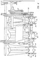
- a pear processing apparatus according to the present invention is shown. Pears are fed into the apparatus at the upper end of apparatus 10 at which a portion of the roll orientor 20 is shown. As will be described in greater detail hereafter, the pears are oriented with their stems extending downwardly and their blossom ends extending upwardly by the roll orientor 20, are dropped downwardly through portions of the mechanism, not visible in Figs. 1 and 2.
- the coring, peeling and seed celling station is shown generally as 11 in Fig. 1.
- Figs. 2 through 5 show the roll orienting mechanism of the present invention.
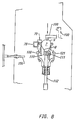
- a singulation device 12 is provided having a plurality of plates 13 which are alternately oscillated in the direction of arrows 14 to present pears one at a time to the upper end of chute 21.
- a typical pear 7 is shown in Fig. 2 with its stem end 8 extending downwardly and its blossom end 9 extending upwardly The blossom end 9 is sometimes referred to herein as the butt end and carries the calyx 6.
- the taper of the chute causes the pears to tumble downwardly with the stem end 8 and blossom end 9 alternately contacting the floor of chute 21, as shown best in Fig. 3.
- the pear tumbles downwardly until it contacts gate 22.
- gate 22 is opened to its position shown in phantom in Fig. 3, the pear 7 tumbles downwardly on chute 21 and onto orienting rolls 30 and 31.
- Back roll 30 and front roll 31 are mounted for rotation upon spaced horizontal axes 32 and 33, respectively.
- roll 30 has a left side 34 and right side 35. The rolls are driven by drive belts 39.
- the three chutes and roll orientors shown in Fig. 4 are shown at three different elevational viewing point with different components broken away.
- Each back roll 30 carries a plurality of whiskers 36 on its left side 34 and a plurality of whiskers 37 on its right side 35.
- Each of the whiskers 36 and 37 extends in a direction radially outward from the axis of rotation 32 of the roll.
- the whiskers 36 and 37 urge the stems of misoriented pears extending beyond the left side 34 or the right side 35 of the roll toward the center of the roll.
- the whiskers help avoid the problem of prior art roll orientors taking excessive time to locate the stem of the pear and to tumble the pear to a position shown in Fig. 3 wherein the pear is positioned between rolls 30 and 31 with it stem end 8 extending downwardly.
- the whiskers 36 and 37 tend to shorten the time necessary for the rolls 30 and 31 to tumble the pear to the position shown in Fig. 3, wherein the stem of the pear extends downwardly.
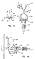
- each front roll 31 is divided into symmetrical halves 31a and 31b, each carried by drive shafts 49a and 49b.
- a pear 7 tumbles in the space between halves 31a and 31b and roll 30.
- a friction clutch means 40 is provided for interrupting driving power to both halves 31a and 31b of front roll 31 when a pear is properly oriented between a pair of roll 30 and 31.
- friction clutch 40 allows both halves of roll 31 to stop rotating about axis 33.
- the friction clutch means 40 (Fig. 31) is preferably achieved by utilizing a wave spring 42 on each of roll halves 31a and 31b carried between each roll half and an adjustable collar 43 having a set screw 44. Roll 31 and collar 43 are carried by bushing 45 having a flange 46 at one end and set screw 48. Wave spring 42 rides against one side of each roll half. Collar 43 applies a predetermined amount of pressure against wave spring 42. When pear 7 is properly oriented, roll 31 stops rotating on its shaft 49.
- a pear stop means 50 is provided and is carried by back roll 30.
- Pear stop means 50 comprises a vertical or nearly vertical plate 51 which pivots about the axis 32 of roll 30.
- the lower end of plate 51 is offset slightly from the vertical to the right in Fig. 3 to sustain pear 7 as close to vertical as possible.
- the purpose of pear stop means 50 is to help retain the pear 7 as shown in Fig. 3 in its vertical position and to help prevent pear 7 from rotating in the direction of arrows 54.
- the stem 8 of pear 7 tends to rotate backwardly towards the axis of rotation 32 of back roll 30 as the rolls of 30 and 31 are separated to their positions shown in Fig. 5 (and as shown in phantom in Fig. 3).
- Cylinder 55 and linkage arms 56 and 57 hold pear stop means 50 in its nearly vertical or extended position as shown in Fig. 3.
- pear stop cylinder 55 is activated, moving pear stop means 50 to its retracted position shown in Fig 5.
- Pear stop means 50 is moved to its retracted position out of contact with pear 7 abruptly as rolls 30 and 31 are separated in order to keep the pear 7 from rotating in the directions of arrows 54 shown in Fig. 3.
- the rolls 30 and 31 are disengaged and separated from the surface of pear 7 slightly prior to the time that pear stop means 50 is retracted so that pear 7 retains its proper alignment with the stem 8 extending downwardly and the blossom end extending upwardly.
- Rolls 30 and 31 are carried by bars 60 and 61, respectively, which in turn are pivoted about shaft 62.
- a roll separation cylinder 63 is connected by linkage arms 64 and 65 respectively, to bars 60 and 61. When roll separation cylinder 63 is activated, linkage arms 64 and 65 operate to separate bars 60 and 61 and the axes of rotation 32 and 33 of rolls 30 and 31.
- Rolls 30 and 31 are separated and, either slightly before or simultaneously with their separation, pear stop means 50 is retracted, so that the points of contact between the pear 7 and the orienting rolls 30 and 31 and with pear stop means 50 are separated from the surface of pear 7 abruptly and nearly simultaneously. This allows pear 7 to fall downwardly along the path of arrow 68 in Fig. 5 into transfer cup means 70.
- Transfer cup means 70 is shown best in Figs. 6 and 7.
- Transfer cup means 70 comprises four fingers 71, 72, 73, 74 and which form a generally "x" shaped array. Each finger extends downwardly towards the center of the "x" at a rest angle of between 30° and 60° to the horizontal. Each finger may be pushed downwardly against a spring loaded support until it forms an angle to the horizontal which approaches 90°.
- Each of the fingers is resiliently mounted as by a spring 75 shown in Fig. 6.
- Fingers 71 and 72 are carried by angle support 76 and fingers 73 and 74 are carried by angle support 77.
- Angle supports 76 and 77 are carried by frame member 78. Angle supports 76 and 77 extend in a parallel fashion away from frame member 78 forming an opening 79 between the ends of angle supports 76 and 77 distal from frame member 78. Opening 79 receives a pusher 100 described below.
- each of the fingers 71-74 is pivotally mounted by pins 81-84, respectively, to brackets 85 and 86 carried by angle support 76 and brackets 87 and 88 carried by angle support 77.
- each of fingers 71-74 is resiliently mounted, a pear dropping downwardly into the center of the "x" formed by fingers 71-74 will experience equal pressure from each finger and will tend to remain centered in the "x.” However, if the pear falls into the "x" off center, the resilient finger or fingers against which the pear has fallen tend to urge the pear toward the center of the "x” with a force proportional to how far off center the pear is.
- the four resiliently mounted fingers therefore cooperate to urge an off center pear towards the center of the "x” formed by the four fingers.
- the preferred number of fingers is four as shown in Figs. 6 and 7.
- Transfer cup means 70 moves vertically between an upper or first position shown in Fig. 5 in which it receives a pear dropping from the orienting rolls 30 and 31 to a lower or second position shown in Fig. 8. Transfer cup means 70 moves downwardly along the path of arrow 89 in Fig. 5 to its lower or second position shown in phantom as 70a in Fig. 5 and as also shown in Fig. 8. Support frame 78 carries transfer cup means 70 between its upper and lower positions shown in Fig. 5 and Fig. 8, respectively.
- transfer cup means 70 begins traveling upwardly.
- pusher 100 maintains contact with the blossom end 9 of pear 7.
- the resiliently mounted fingers 71-74 tend to center the stem of the pear in the center of the "x" formed by those fingers. As this centering occurs, the blossom end 9 of pear 7 is free to slide against its contact point with pusher 100.
- Feed cup means 110 includes a generally concave shaped receptacle 111 having downwardly sloping walls which assist in centering the stem end 8 of the pear as it is urged into feed cup means 110 by pusher 100.
- receptacle 111 is carried by a pressure loaded shaft 112 having a constant upwardly extending biased pressure which may be exerted by a spring acting between transfer bar 140 and the base plate 117 which supports receptacle 111.
- Base plate 117 is carried at the top of shaft 112.
- the lower end 113 of shaft 112 is a free end.
- the purpose of pressure loading shaft 112 is to account for the varying vertical dimensions of pears 7 between their stem and blossom ends. As pusher 100 urges pear 7 downwardly, the stem end 8 of pear 7 contacts the receptacle 111 of feed cup means 110.
- Pusher 110 continues to urge pear 7 downwardly against pressure loaded shaft 112 until pusher 110 reaches a predetermined "set height" for the blossom end 9 of pear 7. This particular "set height” is used to register the blossom end of the pear into proper alignment with the peeling and seed celling means as discussed below.
- a plurality of arms 120, 121 and 122 extending upwardly relative to said feed cup receptacle engage and center the blossom end 9 of pear 7.
- Arms 120, 121 and 122 are all identical, each pivoting about a horizontal axis 121a.
- the lower end 121b of arm 121 is driven inwardly and outwardly by a cam surface 121c.
- the upper end of each arm carries a plastic pad 124, 125 and 126, each of which is pivotally connected to each of the arms and each contacts the blossom end 9 of the pear 7.
- the lower end 121b of arm 121 is a cam follower, which follows the cam surface 121c.
- Each of the arms 120, 121 and 122 will move simultaneously and will therefore tend to center the blossom end 9 of the pear 7 as the pads 124, 125 and 126 contact the pear.
- a variable force drive means for driving arms 120, 121 and 122 includes an adjustable pressure air cylinder 128 which drives connecting rod 129. This feature allows a predetermined amount of force to be applied to the pear by arms 120, 121 and 122 to account for pears of different degrees of softness.
- blossom trim means 130 comprising blossom trim blades 131 and 132 which rotate about pivot 133.
- blossom trim blades 131 and 132 are driven in the path of arrows 134 and 135, respectively, by drive levers 136 and 137, respectively.
- drive lever 136 is driven to the right in Fig. 12 by pin 138, blade 132 is driven downwardly in the direction of arrow 135.
- lever 137 is driven to the left in Fig.
- Lever 136 is connected to blade 132 by link 136a. A similar link joins lever 137 to blade 131.
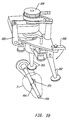
- Coring tube 150 is a hollow cylindrical tube having a distal end 151 an a proximal end 152. Coring tube 150 carries near its distal end, 151 a pair of turning fins 153 and 154.
- the pear 7 has been impaled upon coring tube 150.
- Arms 120, 121 and 122 have been opened after the pear has been impaled on the coring tube.
- feed cup means 110 backs up slightly, and turning fins 153 and 154 begin to rotate, causing the pear 7 to rotate with the coring tube 150.
- a stem trim knife 160 carried by feed cup means 110 is activated by stem trim cylinder 161, advancing stem trim knife blade 162 downwardly into position to sever the pear stem as the pear is rotated.
- the stem is trimmed and thereafter the feed cup assembly 110 is retracted and peeling begins by motion of peeling knives 201 and 202, each peeling approximately one-half of the pear.
- Rotary cutter 201 starts at the blossom end 9 of pear 7 and, as the pear is rotated on coring tube 150, rotary cutter 201 begins rotating and moves from blossom end 9 to approximately the center of the pear 7.
- rotary peeling knife 202 begins approximately at the center of pear 7 and moves to the right in Fig. 15 to the stem 8 of the pear 7.
- the peeling knives are described in greater detail in U.S. patent 5,027,699 dated July 2, 1991 and entitled "Peeling Head.”
- a seed celler knife means 170 rotates with them. However, during the last full revolution of the pear 7 caused by turning fins 153 and 154, the seed celling knife means 170 is held stationary as will be described below and, during this final revolution of the pear 7, the seed cell of the pear is severed by the seed celler knife means 170.
- Fig. 18 shows the rotary peeling cutters which are described in full in U.S. patent 5,027,699. Peeling cutters 201 and 202 are driven by a drive wheel 204 and are moved on and off the pear by kick out lever 205 and are moved forward in the peeling cycle by lever 206.
- seed celler knife means 170 comprises two blades 171 and 172 carried by hollow, cylindrical seed celler support tube 180, having a proximal end 181 and a distal end 182. Seed celler blades 171 and 172 are carried by seed celler support tube 180 near its distal end 182.
- Coring tube 150 which is a hollow and cylindrical tube, has a proximal end 151 and a distal end 152.
- Goring tube 150 extends through seed celler support tube 180, the distal end 152 of coring tube extending beyond the distal end 182 of the seed celler support tube 180 and at least one turning fin 153 or 154 is carried by the distal end 152 of coring tube 150.
- two turning fins are utilized mounted 180 degrees apart.
- Seed celler blades 171 and 172 are aligned with turning fins 153 and 154 so that, as turning fins 153 and 154 rotate to cause pear 7 to rotate, seed celling blades 171 and 172 rotate with turning fins 153 and 154.
- Figs. 21 and 22 show in greater detail the drive mechanism for the coring tube 150 and seed celler support tube 180.
- the coring tube drive pulley 159 receives power from a pulley 281 driven by stepping motor 280 (Fig. 17) and transmits the power directly to coring tube 150 and indirectly to seed celler support tube 180 through a disengageable drive pin 156.
- power from the coring tube drive pulley 155 to the seed celling support tube 180 is disengaged by separating drive pin 156 from a movable plate 175.
- drive pin 156 is fully engaged with plate 175. In this mode, power is being transmitted from pin 156 through plate 175 directly to the seed celler support tube 180.
- Fig. 21 and 22 show in greater detail the drive mechanism for the coring tube 150 and seed celler support tube 180.
- the coring tube drive pulley 159 receives power from a pulley 281 driven by stepping motor 280 (Fig. 17) and transmits the power directly to coring tube 150 and indirectly to seed
- the power to the seed celling support tube is engaged and disengaged by cam surface 190 and cam follower 191 (Fig. 20).
- the cam surface 190 is formed in ring 192.
- Ring 192 is moved from the engaged to disengaged positions by bar 194 and block 195 which together cause the ring 192 to rotate between the engaged position shown in Fig. 23 and the disengaged position in Fig. 24.
- the power is disengaged to the seed cell support tube, and simultaneously the brake means are engaged to hold the seed celling knives 171 and 172 stationary.
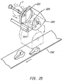
- Fig. 25 shows a slice cup means 220 rotatable between a first or upper position and a second or lower position shown in phantom in Fig. 25.
- a blade 221 is positioned to sever the pear 7 into halves as the knock off disc 210 pushes the pear through blade 221.
- Various blades may be used.
- Slice cup means 220 comprises a generally U shaped container 222 which, in its first or upper position, contains the severed pear halves as shown in Fig. 25.
- Figs. 27-30 show in detail the removable coring and seed celling tubes according to the present invention. Since the coring and seed celling tubes occasionally become bent or otherwise unusable, it is highly beneficial to have a coring tube and seed celling tube assembly which is readily removable and replaceable.
- Fig. 27 shows the replaceable coring and seed celling tube assembly 350 which includes coring tube 150 and seed celling tube 180, and turning fins 153 and 154 and seed celling knives 171 and 172. The assembly 350 has been separated from the coring tube drive mechanism 250.
- the detachable mounting means is shown generally as 260 and includes a pair of spring loaded dogs 261 and 262 carried by the coring tube drive means 250 which engage a pair of holes 271 and 272 formed in the surface of coring tube 150 and seed celler support tube 180. Additionally a second pair of dogs, 263 and 264 engage a pair of U shaped openings 273 and 274 formed in the proximal end of coring tub, 150 and seed celler support tube 180 (Figs. 28,29).
- Fig. 28 shows the unit in normal operation with the dog 261 and 262 fully engaged in holes 271 and 272 and dogs 263 an 264 fully engaged in the U shaped recesses 273 and 274.
- the dogs are maintained in the position shown in Fig. 28 by spring 265.
- a tool is inserted into the end of hollow coring tube 150 and pressed against the solid wedged shaped piece 266 which, as it is driven to the left, pulls dogs 261 and 262 inwardly as shown in Fig. 29 so that the coring and seed celling tube assembly 350 may be separated from the core tube drive mechanism 260 as shown in Fig. 30.
- a new assembly 350 can thereafter be snapped into position.
- the time required to remove and replace assembly 350 in this fashion is merely a matter of seconds.
Abstract

Description
- This invention relates generally to pear processing machines. More particularly, the invention relates to a method and apparatus for peeling, coring, seed celling and trimming pears of various sizes and shapes.
- Pear processing machinery and methods are known in the prior art. However, this prior art technology suffers from certain drawbacks. For example, the prior art machines and methods tend to be less efficient and the machinery tends to utilize more floor space than is desirable. Prior art machines and methods tend to be comparatively slow in processing pears and do not always orientate the pears correctly. Prior art machines and methods have a tendency to split the pear during the seed celling operation and are less efficient at separating the useable portions of the fruit from waste portions. Also, the prior art machines can be difficult to maintain due to the fact that they have a large number of parts.
- The general terms, the present invention provides and apparatus and method for efficiently processing pears.
- The apparatus includes a pear orienting mechanism which receives singulated pears from a feeder and tumbles the pears on orienting rolls until the stems are pointing downwardly. As each pear is properly oriented with its stem pointing downwardly, it is dropped into a transfer cup having a secondary mechanism for orienting misaligned pears. The transfer cup uses a plurality of resilient, spring loaded fingers wherein a misoriented pear tends to be oriented by one or more of those fingers.
- Each pear is discharged from the transfer cup into a feed cup having a generally concave receptacle for receiving the stem of the pear and having a plurality of arms extending upwardly for grasping and centering the blossom or large end of the pear. The feed cup in effect offers a third orienting mechanism for properly aligning and positioning the pear.
- A pusher and set height mechanism is utilized which positions the blossom end of each pear at a predetermined height to register the blossom end of the pear with the peeling and seed celling portion of the apparatus. The feed cup mechanism presents the pear to the coring, peeling and seed celling portion of the apparatus wherein peeling and seed celling occur simultaneously after the pear has been cored.
- One object of the invention is the provision of a set height mechanism for positioning the blossom end of the pear at a predetermined height in the apparatus so that the pear can be properly located and aligned for the coring, peeling and seed celling operations.
- Another aspect of the invention is that the pear processing apparatus is capable of simultaneously peeling and seed celling pears automatically.
- Still another aspect of the invention is that the pear processing machine utilizes a roll orientor for orienting singulated pears into a position wherein the pear stem extends downwardly, and that whiskers are provided on the roll orientor to more quickly and more efficiently orient the pears.
- A further aspect of the invention is a roll orientor for pears incorporating a friction clutch mechanism wherein at least one of the orientor rolls stops rotating when the pear becomes properly oriented.
- A further aspect of the invention is a transfer cup for receiving the pears from the orientor, wherein the transfer cup provides an additional measure of orienting of misaligned pears.
- A still further aspect of the invention is a feed cup mechanism for receiving the pears from the transfer cup wherein the feed cup mechanism provides a further mechanism for orienting misaligned pears. The feed cup mechanism incorporates a concave receptacle for locating and positioning the stem of a pear, and in addition a plurality of arms which move simultaneously to grasp and center the blossom end of the pear.
- A further aspect of the invention is the provision of a replaceable coring tube which may be readily removed and replaced.
- A still further aspect of the invention is that the pear processing apparatus includes both blossom trim and stem trim mechanisms for efficiently and dependably trimming the blossom and stem ends of the pear.
- Another aspect of the invention is that the pear processing apparatus includes a slice cup mechanism for slicing the processed pears into a predetermined number of slices, for separating the usable product from the waste and for effectively transferring the usable sliced product to a discharge conveyor belt.
- Another still further aspect of the invention is a method for processing pears which includes multiple independent steps for properly orienting the pear as well as the step of simultaneously peeling and seed celling the pears.
- Other aspects, features, and advantages of the invention will become apparent from the following description of the preferred embodiments and the drawings wherein:
- Fig. 1 is a perspective view of the pear processing apparatus according to the present invention;
- Fig. 2 is a schematic representation of the pear singulator and roll orientor:
- Fig. 3 is a side view of the roll orientor;
- Fig. 4 is a front view of the roll orientor showing various portions of the orientor broken away;
- Fig. 5 is a schematic representation of the roll orientor after the roll orientor has dropped a pear downwardly into the transfer cup;
- Fig. 6 is a perspective view of the transfer cup according to the present invention;
- Fig. 7 is a plan view of the transfer cup according to the present invention;
- Fig. 8 is a schematic representation of the pear being pushed downwardly out of the transfer cup and into the feed cup and set height mechanism;
- Fig. 9 is a sectional view of the feed cup mechanism and set height mechanism according to the present invention;
- Fig. 10 is a top view of the feed cup mechanism of Fig. 9;
- Fig. 11 is a perspective view of the pusher mechanism which also includes the blossom trim knives according to the present invention;
- Fig. 12 is a sectional view of the apparatus shown in Fig. 11
- Fig. 13 is a schematic representation of the feed cup and set height mechanisms after the pear height has been set, the pear has been grasped by the feed cup assembly and wherein the pear is about to be presented to the coring, peeling and seed celling mechanism;
- Fig. 14 is a schematic representation of the pear and feed cup assembly having made a 90° turn and having pushed the pear onto the coring tube and having properly positioned the pear for peeling and seed celling;
- Fig. 15 is a schematic representation of the pear having been peeled, showing the mechanism for pushing out the pear core from the coring tube and showing the seed celler actuator assembly;
- Fig. 16 is a bottom view showing schematically the path of the peeling knives over the surface of the pear;
- Fig. 17 is a schematic representation showing the pear knockoff disc discharging the pear from the coring tube into the slice cup mechanism;
- Fig. 18 is a perspective view of the peeling cutter mechanism;
- Fig. 19 is a sectional view of the internal portion of the coring and seed celling mechanism of the present invention;
- Fig. 20 is a side elevational view of the seed celler knife assembly, the coring tube and the drive mechanism for the seed celler and the coring tube;
- Fig. 21 is a sectional view of a portion of the drive mechanism for the seed celler knives and the coring tube, wherein the seed celling knives rotate with the turning fins carried by the coring tube;
- Fig. 22 is a sectional view of the drive mechanism shown in Fig. 21 wherein the seed celling knives are held stationary while the turning fins and coring tube continue to rotate;
- Fig. 23 is a sectional view of a portion of the coring tube and seed celler support tube drive means wherein the coring tube is rotating with the seed celler support tube;
- Fig. 24 is a sectional view of a portion of the drive means for the coring tube and seed celler support tube where: the seed celler knives are held stationary but wherein the coring tube continues to rotate;
- Fig. 25 is a perspective view of the pear knockoff disc discharging a processed pear from the coring tube into the slice cup mechanism and which shows in phantom the discharge position of the slice cup;
- Fig. 26 is a schematic representation showing the slice cup discharging the usable sliced pears onto a discharge conveyor;
- Fig. 27 is a perspective view, partially exploded, showing the replaceable coring tube according to the present invention;
- Fig. 28 is a sectional view of the coring tube mounting mechanism showing a coring tube mounted for normal operation;
- Fig. 29 is a sectional view of the coring tube mounting mechanism as the coring tube has been pressed inwardly to detach the coring tube from its mounting;
- Fig. 30 is a sectional view of the coring tube mounting mechanism showing the replaceable coring tube being removed from its mounting, and
- Fig. 31 is a sectional view of a front roll showing the friction clutch mechanism.
-
- Referring to Fig. 1, a pear processing apparatus according to the present invention is shown. Pears are fed into the apparatus at the upper end of
apparatus 10 at which a portion of theroll orientor 20 is shown. As will be described in greater detail hereafter, the pears are oriented with their stems extending downwardly and their blossom ends extending upwardly by theroll orientor 20, are dropped downwardly through portions of the mechanism, not visible in Figs. 1 and 2. The coring, peeling and seed celling station is shown generally as 11 in Fig. 1. - Figs. 2 through 5 show the roll orienting mechanism of the present invention.
- A
singulation device 12 is provided having a plurality ofplates 13 which are alternately oscillated in the direction ofarrows 14 to present pears one at a time to the upper end ofchute 21. Atypical pear 7 is shown in Fig. 2 with itsstem end 8 extending downwardly and itsblossom end 9 extending upwardly Theblossom end 9 is sometimes referred to herein as the butt end and carries thecalyx 6. - As the pear enters
chute 21, the taper of the chute, shown best in Fig. 4, causes the pears to tumble downwardly with thestem end 8 and blossomend 9 alternately contacting the floor ofchute 21, as shown best in Fig. 3. The pear tumbles downwardly until itcontacts gate 22. Asgate 22 is opened to its position shown in phantom in Fig. 3, thepear 7 tumbles downwardly onchute 21 and onto orienting rolls 30 and 31. Back roll 30 andfront roll 31 are mounted for rotation upon spacedhorizontal axes left side 34 andright side 35. The rolls are driven bydrive belts 39. The three chutes and roll orientors shown in Fig. 4 are shown at three different elevational viewing point with different components broken away. - Each back roll 30 carries a plurality of
whiskers 36 on itsleft side 34 and a plurality ofwhiskers 37 on itsright side 35. Each of thewhiskers rotation 32 of the roll. Thewhiskers left side 34 or theright side 35 of the roll toward the center of the roll. The whiskers help avoid the problem of prior art roll orientors taking excessive time to locate the stem of the pear and to tumble the pear to a position shown in Fig. 3 wherein the pear is positioned betweenrolls end 8 extending downwardly. Thewhiskers rolls - As shown best in Fig. 31, each
front roll 31 is divided into symmetrical halves 31a and 31b, each carried by drive shafts 49a and 49b. Apear 7 tumbles in the space between halves 31a and 31b androll 30. A friction clutch means 40 is provided for interrupting driving power to both halves 31a and 31b offront roll 31 when a pear is properly oriented between a pair ofroll stem 8 downwardly betweenrolls butt end 9 upwardly, the friction generated between thepear 7 and rolls 30 and 31 is maximized. When this position ofpear 7 is achieved, friction clutch 40 (shown best in Fig. 31) allows both halves ofroll 31 to stop rotating aboutaxis 33. By stopping the rotation ofroll 31, we have found thatpear 7 tends to remain aligned between the pair ofrolls Roll 31 and collar 43 are carried by bushing 45 having a flange 46 at one end and set screw 48. Wave spring 42 rides against one side of each roll half. Collar 43 applies a predetermined amount of pressure against wave spring 42. Whenpear 7 is properly oriented, roll 31 stops rotating on its shaft 49. - A pear stop means 50 is provided and is carried by
back roll 30. Pear stop means 50 comprises a vertical or nearlyvertical plate 51 which pivots about theaxis 32 ofroll 30. The lower end ofplate 51 is offset slightly from the vertical to the right in Fig. 3 to sustainpear 7 as close to vertical as possible. The purpose of pear stop means 50 is to help retain thepear 7 as shown in Fig. 3 in its vertical position and to help preventpear 7 from rotating in the direction ofarrows 54. Thestem 8 ofpear 7 tends to rotate backwardly towards the axis ofrotation 32 ofback roll 30 as the rolls of 30 and 31 are separated to their positions shown in Fig. 5 (and as shown in phantom in Fig. 3).Cylinder 55 andlinkage arms pear stop cylinder 55 is activated, moving pear stop means 50 to its retracted position shown in Fig 5. Pear stop means 50 is moved to its retracted position out of contact withpear 7 abruptly asrolls pear 7 from rotating in the directions ofarrows 54 shown in Fig. 3. Therolls pear 7 slightly prior to the time that pear stop means 50 is retracted so thatpear 7 retains its proper alignment with thestem 8 extending downwardly and the blossom end extending upwardly. -
Rolls bars shaft 62. Aroll separation cylinder 63 is connected bylinkage arms bars roll separation cylinder 63 is activated,linkage arms bars rotation rolls -
Rolls pear 7 and the orienting rolls 30 and 31 and with pear stop means 50 are separated from the surface ofpear 7 abruptly and nearly simultaneously. This allowspear 7 to fall downwardly along the path ofarrow 68 in Fig. 5 into transfer cup means 70. - Transfer cup means 70 is shown best in Figs. 6 and 7. Transfer cup means 70 comprises four
fingers spring 75 shown in Fig. 6.Fingers angle support 76 andfingers angle support 77. Angle supports 76 and 77 are carried byframe member 78. Angle supports 76 and 77 extend in a parallel fashion away fromframe member 78 forming anopening 79 between the ends of angle supports 76 and 77 distal fromframe member 78.Opening 79 receives apusher 100 described below. - As shown in Fig. 6, each of the fingers 71-74 is pivotally mounted by pins 81-84, respectively, to
brackets angle support 76 andbrackets angle support 77. - Since each of fingers 71-74 is resiliently mounted, a pear dropping downwardly into the center of the "x" formed by fingers 71-74 will experience equal pressure from each finger and will tend to remain centered in the "x." However, if the pear falls into the "x" off center, the resilient finger or fingers against which the pear has fallen tend to urge the pear toward the center of the "x" with a force proportional to how far off center the pear is. The four resiliently mounted fingers therefore cooperate to urge an off center pear towards the center of the "x" formed by the four fingers. Although it is possible to use a number of fingers different than the four shown, the preferred number of fingers is four as shown in Figs. 6 and 7.
- Transfer cup means 70 moves vertically between an upper or first position shown in Fig. 5 in which it receives a pear dropping from the orienting rolls 30 and 31 to a lower or second position shown in Fig. 8. Transfer cup means 70 moves downwardly along the path of
arrow 89 in Fig. 5 to its lower or second position shown in phantom as 70a in Fig. 5 and as also shown in Fig. 8.Support frame 78 carries transfer cup means 70 between its upper and lower positions shown in Fig. 5 and Fig. 8, respectively. - Once the transfer cup means 70 has carried the pear to its lowermost position shown in Fig. 8, a
pusher arm 100 is rotated from a vertical position shown in phantom in Fig. 8 to a horizontal position shown in Fig. 8, where it contacts theblossom end 9 ofpear 7. After this contact is made, transfer cup means 70 begins traveling upwardly. As transfer cup means 70 moves upwardly,pusher 100 maintains contact with theblossom end 9 ofpear 7. Ifpear 7 is somewhat misaligned, as transfer cup means 70 moves upwardly, the resiliently mounted fingers 71-74 tend to center the stem of the pear in the center of the "x" formed by those fingers. As this centering occurs, theblossom end 9 ofpear 7 is free to slide against its contact point withpusher 100. - As the transfer cup means 70 moves upwardly, as shown in Fig. 8,
pusher 100 also begins pushingpear 7 downwardly. After the blossom end of the pear moves the fingers 71-74 of the transfer cup to their nearly vertical position shown in Fig. 8, thestem end 8 ofpear 7 is urged into feed cup means 110. Feed cup means 110 includes a generally concave shapedreceptacle 111 having downwardly sloping walls which assist in centering thestem end 8 of the pear as it is urged into feed cup means 110 bypusher 100. - As shown best in Fig. 9,
receptacle 111 is carried by a pressure loadedshaft 112 having a constant upwardly extending biased pressure which may be exerted by a spring acting betweentransfer bar 140 and thebase plate 117 which supportsreceptacle 111.Base plate 117 is carried at the top ofshaft 112. Thelower end 113 ofshaft 112 is a free end. The purpose ofpressure loading shaft 112 is to account for the varying vertical dimensions ofpears 7 between their stem and blossom ends. Aspusher 100 urgespear 7 downwardly, thestem end 8 ofpear 7 contacts thereceptacle 111 of feed cup means 110.Pusher 110 continues to urgepear 7 downwardly against pressure loadedshaft 112 untilpusher 110 reaches a predetermined "set height" for theblossom end 9 ofpear 7. This particular "set height" is used to register the blossom end of the pear into proper alignment with the peeling and seed celling means as discussed below. - When
pusher 100 has urged theblossom end 9 ofpear 7 to the predetermined "set height," the pressure loadedshaft 112 supporting thefeed cup receptacle 111 is locked into position bymovable bar 114 with a serrated edge moving to the left in Fig. 9 to engage theserrations 115 formed on the surface ofshaft 112. - Shortly before the
movable bar 114locks shaft 112 into position, a plurality ofarms blossom end 9 ofpear 7.Arms arm 121 is driven inwardly and outwardly by a cam surface 121c. The upper end of each arm carries aplastic pad blossom end 9 of thepear 7. As shown best in Fig. 10, the lower end 121b ofarm 121 is a cam follower, which follows the cam surface 121c. Each of thearms blossom end 9 of thepear 7 as thepads - A variable force drive means for driving
arms pressure air cylinder 128 which drives connectingrod 129. This feature allows a predetermined amount of force to be applied to the pear byarms - After the pear has been grasped by the three
arms feed cup receptacle 111, the blossom end of the pear is trimmed by blossom trim means 130 comprising blossom trimblades pivot 133. As shown best in Figs. 11 and 12, blossom trimblades arrows drive levers drive lever 136 is driven to the right in Fig. 12 bypin 138,blade 132 is driven downwardly in the direction ofarrow 135. Simultaneously,lever 137 is driven to the left in Fig. 12 bypin 139 which rotates blossomtrim blade 131 in the direction ofarrow 134 to achieve a generally hemispherical cut trimming the calyx from theblossom end 9 of thepear 7.Lever 136 is connected toblade 132 by link 136a. A similar link joinslever 137 toblade 131. - As shown in Fig. 13, the feed cup assembly including the feed cup means 110, the three
arms shaft 112 and theserrated locking piece 114 are separated from the pusher means and is carried bytransfer bar 140 through a 90° turn and drives the pear onto thecoring tube 150.Coring tube 150 is a hollow cylindrical tube having adistal end 151 an aproximal end 152.Coring tube 150 carries near its distal end, 151 a pair of turningfins - As shown in Fig. 14, the
pear 7 has been impaled uponcoring tube 150.Arms fins pear 7 to rotate with thecoring tube 150. - As the pear is rotated by the
coring tube 150 and turningfins trim knife 160 carried by feed cup means 110 is activated by stemtrim cylinder 161, advancing stemtrim knife blade 162 downwardly into position to sever the pear stem as the pear is rotated. During the first complete revolution of thepear 7, the stem is trimmed and thereafter thefeed cup assembly 110 is retracted and peeling begins by motion of peelingknives Rotary cutter 201 starts at theblossom end 9 ofpear 7 and, as the pear is rotated oncoring tube 150,rotary cutter 201 begins rotating and moves fromblossom end 9 to approximately the center of thepear 7. Simultaneously,rotary peeling knife 202 begins approximately at the center ofpear 7 and moves to the right in Fig. 15 to thestem 8 of thepear 7. The peeling knives are described in greater detail in U.S. patent 5,027,699 dated July 2, 1991 and entitled "Peeling Head." - As the
pear 7 is being rotated by turningfins pear 7 caused by turningfins pear 7, the seed cell of the pear is severed by the seed celler knife means 170. - During peeling the core 7a is pushed out of
coring tube 150 by core push-outrod 155. - As shown in Fig. 17, when the peeling operation has been concluded, the pear is pushed off the
coring tube 150 by aknockoff disc 210 which drives the pear intoslice cup 220, shown in greater detail in Figs. 25 and 26 below. - Fig. 18 shows the rotary peeling cutters which are described in full in U.S. patent 5,027,699. Peeling
cutters drive wheel 204 and are moved on and off the pear by kick outlever 205 and are moved forward in the peeling cycle bylever 206. - Referring to Fig. 20, seed celler knife means 170 comprises two
blades celler support tube 180, having aproximal end 181 and adistal end 182.Seed celler blades celler support tube 180 near itsdistal end 182. -
Coring tube 150, which is a hollow and cylindrical tube, has aproximal end 151 and adistal end 152.Goring tube 150 extends through seedceller support tube 180, thedistal end 152 of coring tube extending beyond thedistal end 182 of the seedceller support tube 180 and at least oneturning fin distal end 152 ofcoring tube 150. In the preferred embodiment, two turning fins are utilized mounted 180 degrees apart. -
Seed celler blades fins fins pear 7 to rotate,seed celling blades fins - Figs. 21 and 22 show in greater detail the drive mechanism for the
coring tube 150 and seedceller support tube 180. The coring tube drivepulley 159 receives power from apulley 281 driven by stepping motor 280 (Fig. 17) and transmits the power directly tocoring tube 150 and indirectly to seedceller support tube 180 through adisengageable drive pin 156. As shown in Fig. 22, power from the coring tube drivepulley 155 to the seedcelling support tube 180 is disengaged by separatingdrive pin 156 from amovable plate 175. As shown in Fig. 23,drive pin 156 is fully engaged withplate 175. In this mode, power is being transmitted frompin 156 throughplate 175 directly to the seedceller support tube 180. However, as shown in Fig. 24, which corresponds to Fig. 22, whenplate 175 is moved to the right in Fig. 22 and disengages fromdrive pin 156, the twotangs plate 175 engagestops seed celling knives coring tube 150 and turningfins plate 175,tangs stops - The power to the seed celling support tube is engaged and disengaged by
cam surface 190 and cam follower 191 (Fig. 20). Thecam surface 190 is formed inring 192.Ring 192 is moved from the engaged to disengaged positions bybar 194 and block 195 which together cause thering 192 to rotate between the engaged position shown in Fig. 23 and the disengaged position in Fig. 24. In the disengaged position shown in Fig. 24, the power is disengaged to the seed cell support tube, and simultaneously the brake means are engaged to hold theseed celling knives - Fig. 25 shows a slice cup means 220 rotatable between a first or upper position and a second or lower position shown in phantom in Fig. 25. In the first or upper position, a
blade 221 is positioned to sever thepear 7 into halves as the knock offdisc 210 pushes the pear throughblade 221. Various blades may be used. Slice cup means 220 comprises a generally U shapedcontainer 222 which, in its first or upper position, contains the severed pear halves as shown in Fig. 25. After the pear halves have been deposited inslice cup 222, the slice cup is rotated downwardly aboutshaft 223 in a rather abrupt fashion to fling the pear halves downwardly against an inclined processedpear discharge chute 230 onto processedpear conveyor 232, shown best in Fig. 26. By flinging the slice cup downwardly towardchute 230, the usable pear portions are more effectively separated from the waste seed cell. Whenslice cup 222 is in its downward position, in which it forms a generally inverted U-shape,cup 222 effectively surrounds the upper portion ofdischarge chute 230. Any waste product that drops ontocup 222 tends to slide offcup 222 and into the waste discharge chute formed bywalls waste conveyor 231 receives waste from waste discharge chute having inclinedwalls conveyor 232 removes the usable pear product and as little as possible of the waste. - Figs. 27-30 show in detail the removable coring and seed celling tubes according to the present invention. Since the coring and seed celling tubes occasionally become bent or otherwise unusable, it is highly beneficial to have a coring tube and seed celling tube assembly which is readily removable and replaceable. Fig. 27 shows the replaceable coring and seed
celling tube assembly 350 which includescoring tube 150 andseed celling tube 180, and turningfins seed celling knives assembly 350 has been separated from the coringtube drive mechanism 250. The detachable mounting means is shown generally as 260 and includes a pair of spring loadeddogs holes coring tube 150 and seedceller support tube 180. Additionally a second pair of dogs, 263 and 264 engage a pair of U shapedopenings - Fig. 28 shows the unit in normal operation with the
dog holes dogs 263 an 264 fully engaged in the U shaped recesses 273 and 274. The dogs are maintained in the position shown in Fig. 28 byspring 265. In order to remove theassembly 350, a tool is inserted into the end ofhollow coring tube 150 and pressed against the solid wedgedshaped piece 266 which, as it is driven to the left, pullsdogs celling tube assembly 350 may be separated from the coretube drive mechanism 260 as shown in Fig. 30. Anew assembly 350 can thereafter be snapped into position. The time required to remove and replaceassembly 350 in this fashion is merely a matter of seconds.
Claims (6)
- In a pear orienting apparatus having a set of orienting rolls including at least a pair of rolls mounted for rotation upon spaced horizontal axes, each of said rolls having two sides, drive means for rotating said pair of rolls, and means feeding singulated pears to the top of the rolls intermediate said spaced axes, the improvement comprising:a plurality of whiskers carried by at least one of said pair of rolls, said whiskers extending in a direction radially outward from the axis of rotation of said roll, and said whiskers being located at each end of said roll so that said whiskers urge the stems of pears extending beyond either side of said roll toward the center of said roll.
- The apparatus of claim 1 wherein said drive means further comprises a friction clutch means for interrupting driving power to one of said pair of rolls when a pear is oriented between that pair of rolls with its stem end extending downwardly between said pair of rolls and its blossom end extending upwardly.
- The apparatus of claim 2 further comprising retractable pear stop means extending nearly vertically downward from one of said pair of rolls to contact the stem end of an oriented pear, and means for separating said pair of rolls and simultaneously and abruptly retracting said pear stop means to a position out of contact with said pear.
- In a pear orienting apparatus having a set of orienting rolls including at least a pair of rolls mounted for rotation upon spaced horizontal axes, each of said rolls having two sides, drive means for rotating said pair of rolls, and means feeding singulated pears to the top of the rolls intermediate said spaced axes, the improvement comprising:friction clutch means for interrupting driving power to one of said pair of rolls when a pear is oriented between said pair of rolls with its stem end extending downwardly and its blossom end extending upwardly.
- The apparatus of claim 4 wherein said friction clutch means comprises a wave spring carried between a roll and its drive shaft.
- The apparatus of claim 5 wherein each of said pair of rolls rotates in the same direction about its respective axis of rotation.
Applications Claiming Priority (3)
| Application Number | Priority Date | Filing Date | Title |
|---|---|---|---|
| US08/035,667 US5431095A (en) | 1993-03-23 | 1993-03-23 | Pear processing method and apparatus |
| EP94103917A EP0616781B1 (en) | 1993-03-23 | 1994-03-14 | Pear processing method and apparatus |
| US35667 | 1997-01-21 |
Related Parent Applications (1)
| Application Number | Title | Priority Date | Filing Date |
|---|---|---|---|
| EP94103917A Division EP0616781B1 (en) | 1993-03-23 | 1994-03-14 | Pear processing method and apparatus |
Publications (3)
| Publication Number | Publication Date |
|---|---|
| EP0923881A2 true EP0923881A2 (en) | 1999-06-23 |
| EP0923881A3 EP0923881A3 (en) | 1999-12-15 |
| EP0923881B1 EP0923881B1 (en) | 2003-06-04 |
Family
ID=21884065
Family Applications (3)
| Application Number | Title | Priority Date | Filing Date |
|---|---|---|---|
| EP99104973A Expired - Lifetime EP0923882B1 (en) | 1993-03-23 | 1994-03-14 | Impact seed celler |
| EP99104972A Expired - Lifetime EP0923881B1 (en) | 1993-03-23 | 1994-03-14 | Roll orientor |
| EP94103917A Expired - Lifetime EP0616781B1 (en) | 1993-03-23 | 1994-03-14 | Pear processing method and apparatus |
Family Applications Before (1)
| Application Number | Title | Priority Date | Filing Date |
|---|---|---|---|
| EP99104973A Expired - Lifetime EP0923882B1 (en) | 1993-03-23 | 1994-03-14 | Impact seed celler |
Family Applications After (1)
| Application Number | Title | Priority Date | Filing Date |
|---|---|---|---|
| EP94103917A Expired - Lifetime EP0616781B1 (en) | 1993-03-23 | 1994-03-14 | Pear processing method and apparatus |
Country Status (11)
| Country | Link |
|---|---|
| US (5) | US5431095A (en) |
| EP (3) | EP0923882B1 (en) |
| JP (1) | JP3409914B2 (en) |
| AU (3) | AU671894B2 (en) |
| CA (1) | CA2119631C (en) |
| CL (2) | CL2009000784A1 (en) |
| DE (3) | DE69432195T2 (en) |
| ES (3) | ES2191377T3 (en) |
| GR (1) | GR3032153T3 (en) |
| NZ (1) | NZ260097A (en) |
| ZA (1) | ZA941840B (en) |
Cited By (3)
| Publication number | Priority date | Publication date | Assignee | Title |
|---|---|---|---|---|
| EP1469431A2 (en) * | 2003-04-16 | 2004-10-20 | MR & D Institute S.r.L. | Refrigerated vending machine for fresh fruits |
| CN107736640A (en) * | 2017-11-28 | 2018-02-27 | 徐州果姿电子商务有限公司 | A kind of food processing beans root bark of tree peony meat separator |
| CN108402475A (en) * | 2018-02-13 | 2018-08-17 | 邹宝林 | The position-limit mechanism of lotus seeds machine |
Families Citing this family (26)
| Publication number | Priority date | Publication date | Assignee | Title |
|---|---|---|---|---|
| US5431095A (en) | 1993-03-23 | 1995-07-11 | Atlas Pacific Engineering Company | Pear processing method and apparatus |
| US5454302A (en) * | 1994-03-02 | 1995-10-03 | Atlas Pacific Engineering Company | Pear transfer apparatus and method |
| US5544731A (en) * | 1995-03-27 | 1996-08-13 | Atlas Pacific Engineering Company | Agitating apple orientor |
| US5590591A (en) * | 1996-04-18 | 1997-01-07 | Kim; Sun Y. | Product processing apparatus including orientation and coring of produce items |
| IT1296742B1 (en) | 1997-10-20 | 1999-07-27 | L S R L Ab | PEAR PEELING, DETORING AND SHEARING MACHINE. |
| GB9804833D0 (en) * | 1998-03-07 | 1998-04-29 | Rose David | Improvements in alignment techniques |
| IT1315655B1 (en) * | 2000-07-31 | 2003-03-14 | Abl Srl | AUTOMATIC MACHINE FOR DETORING, PEELING AND SEPARATION IN TWO OR MORE PARTS OF PEARS |
| DE60231234D1 (en) | 2001-12-03 | 2009-04-02 | Atlas Pacifik Eng Co | ADJUSTABLE ALIGNMENT PAN FOR A PEACHING UNIT |
| US7020968B1 (en) * | 2003-09-18 | 2006-04-04 | Abdel-Dayem Bassam A | Fruit and vegetable coring machine |
| US20050077668A1 (en) * | 2003-10-10 | 2005-04-14 | Clouse Michael F. | Modular attachments for surface mount tools |
| NL1027684C2 (en) * | 2004-12-08 | 2006-06-09 | Fwd Exploitatie B V | Device and method for directing objects. |
| US20080302893A1 (en) * | 2007-06-11 | 2008-12-11 | Mah Pat Y | Linear food processor |
| US20100257984A1 (en) * | 2009-04-09 | 2010-10-14 | Scaroni David W | Produce processing apparatus |
| US9221186B2 (en) * | 2009-04-09 | 2015-12-29 | David W. Scaroni | Produce processing apparatus |
| US8586118B1 (en) * | 2010-02-02 | 2013-11-19 | Gene Baca | Method of using a gravity wheel de-stemmer |
| JP2012080851A (en) * | 2010-10-14 | 2012-04-26 | Inamoku:Kk | Core-removing, skin-peeling and dividing apparatus for farm crop such as apple, persimmon, pear and onion |
| AU2012212659B2 (en) | 2011-01-07 | 2016-10-13 | Taylor Commercial Foodservice, LLC. | Method and apparatus for preparing food, particularly fruit |
| CN107455770A (en) * | 2016-06-06 | 2017-12-12 | 刘凯 | The Tool Control system and its method for controlling cutting tools of a kind of fruit peeling |
| CN106723107B (en) * | 2017-01-22 | 2023-06-13 | 江南大学 | Novel hawthorn stoning and slicing device and application |
| CN106666768B (en) * | 2017-02-01 | 2019-03-08 | 叶能慧 | A kind of automation pineapple peeling Xiao Kong robot |
| CN109907336B (en) * | 2019-03-31 | 2021-12-07 | 台州市华丰空调阀门有限公司 | Radish peeling equipment based on vertical winding |
| IT201900014079A1 (en) * | 2019-08-05 | 2021-02-05 | Cti Foodtech S R L | Pear feeding process and equipment for multi-line processing |
| CN112674359B (en) * | 2020-12-29 | 2021-12-10 | 柯炯明 | Equipment for cutting pumpkin peels |
| CN113383971B (en) * | 2021-07-07 | 2022-10-04 | 山东泰乐源农业科技有限公司 | Apple juice and preparation method thereof |
| CN115504039B (en) * | 2022-10-27 | 2023-09-12 | 塔里木大学 | Regional damage-free packaging device for picking pear orchard |
| CN116214605B (en) * | 2023-05-08 | 2023-07-04 | 江苏科威机械有限公司 | Nuclear removal and dicing device for primary processing of yellow peach cans |
Citations (1)
| Publication number | Priority date | Publication date | Assignee | Title |
|---|---|---|---|---|
| US5413206A (en) | 1993-03-23 | 1995-05-09 | Atlas Pacific Engineering Company | Pear processing method and apparatus |
Family Cites Families (35)
| Publication number | Priority date | Publication date | Assignee | Title |
|---|---|---|---|---|
| US1451571A (en) * | 1922-02-13 | 1923-04-10 | Edward E Gay | Apple-preparing machine |
| US1563972A (en) * | 1923-12-29 | 1925-12-01 | Margaret F Fenn | Coring and trimming mechanism |
| US2056413A (en) * | 1931-04-27 | 1936-10-06 | Fmc Corp | Pear preparation machine |
| US2242244A (en) * | 1932-10-06 | 1941-05-20 | Special Equipment Co | Fruit treating apparatus |
| US2097170A (en) * | 1936-11-23 | 1937-10-26 | Wilson Edwin Earl | Paring, slicing, and coring machine |
| US2526712A (en) * | 1939-04-14 | 1950-10-24 | Fmc Corp | Continuously rotating turrets with pear peeling, coring, and splitting means |
| US2913028A (en) * | 1949-10-01 | 1959-11-17 | Fmc Corp | Fruit orienting and pitting mechanism |
| US2738819A (en) * | 1950-09-25 | 1956-03-20 | Fmc Corp | Apparatus for and method of feeding pears |
| US2740441A (en) * | 1951-03-12 | 1956-04-03 | Fmc Corp | Pear feeding, peeling, halving, seed celling, and trimming machine |
| US2742067A (en) * | 1952-03-29 | 1956-04-17 | Burton C Coons | Pear feeding, stemming, end trimming, peeling, seed celling, and halving machine |
| US3018179A (en) * | 1955-11-25 | 1962-01-23 | Burton C Coons | Pear peeling, coring and trimming machine and method and product thereof |
| US3144061A (en) * | 1956-11-30 | 1964-08-11 | Fmc Corp | Fruit splitting machine |
| US2979093A (en) * | 1956-11-30 | 1961-04-11 | Fmc Corp | Pear peeling machine |
| US2910102A (en) * | 1957-01-24 | 1959-10-27 | Windman Albert | Severed piece dislodging mechanism for pear stem end cutters |
| US3055408A (en) * | 1958-10-10 | 1962-09-25 | Atlas Pacifik Eng Co | Pear seed celling mechanism |
| US3058502A (en) * | 1961-02-09 | 1962-10-16 | Atlas Pacifik Eng Co | Rotary-type knife pear peeler |
| US3144121A (en) * | 1962-07-02 | 1964-08-11 | Atlas Pacifik Eng Co | Pear feeder |
| US3317027A (en) * | 1964-12-14 | 1967-05-02 | Philip H Allen | Orienting means and method for fruit and vegetable articles |
| US3332559A (en) * | 1965-07-22 | 1967-07-25 | Atlas Pacifik Eng Co | Air cup |
| US3753397A (en) * | 1968-01-11 | 1973-08-21 | Brown Int Corp | Apparatus for sectionizing citrus fruit |
| US3738474A (en) * | 1971-11-01 | 1973-06-12 | Atlas Pacific Eng Co | Apple orientor |
| US3797639A (en) * | 1972-06-28 | 1974-03-19 | Atlas Pacific Eng Co | Machine for orienting pears |
| US4010842A (en) * | 1973-10-18 | 1977-03-08 | Atlas Pacific Engineering Company | Machine for orienting pears |
| US4005774A (en) * | 1973-12-26 | 1977-02-01 | Compania Hispano Americana de Construcciones Conserveras S.A. (CHACONSA) | Peduncled vegetable and fruit positioning device |
| US4046067A (en) * | 1975-12-03 | 1977-09-06 | Atlas Pacific Engineering Company | Machine for cutting pears into segments |
| US4112838A (en) * | 1976-06-23 | 1978-09-12 | Altman James E | Halving and calyx removing apparatus for pears and the like |
| US4169528A (en) * | 1977-12-12 | 1979-10-02 | Atlas Pacific Engineering Company | Apple orienting system |
| US4907687A (en) * | 1982-07-14 | 1990-03-13 | Atlas Pacific Engineering Company | Pear orienting apparatus |
| US4487307A (en) * | 1982-07-14 | 1984-12-11 | Atlas Pacific Engineering Company | Pear orienting apparatus |
| US4766990A (en) * | 1982-09-30 | 1988-08-30 | Atlas Pacific Engineering Company | Pear orienting and transfer apparatus |
| DE3334709C2 (en) * | 1983-09-24 | 1985-07-25 | Jean Walterscheid Gmbh, 5204 Lohmar | Telescopic shaft |
| US4480536A (en) * | 1983-11-28 | 1984-11-06 | Demco Inc. | Broccoli bunching and cutting apparatus |
| US4706797A (en) * | 1986-03-11 | 1987-11-17 | Carlson Richard L | Apple orientation apparatus and method |
| US4819293A (en) * | 1988-01-11 | 1989-04-11 | Aquality, Inc. | Adapter and pole assembly |
| US5027699A (en) * | 1990-08-20 | 1991-07-02 | Atlas Pacific Engineering Company | Peeling head |
-
1993
- 1993-03-23 US US08/035,667 patent/US5431095A/en not_active Expired - Lifetime
-
1994
- 1994-03-14 EP EP99104973A patent/EP0923882B1/en not_active Expired - Lifetime
- 1994-03-14 ES ES99104973T patent/ES2191377T3/en not_active Expired - Lifetime
- 1994-03-14 ES ES99104972T patent/ES2200428T3/en not_active Expired - Lifetime
- 1994-03-14 EP EP99104972A patent/EP0923881B1/en not_active Expired - Lifetime
- 1994-03-14 DE DE69432195T patent/DE69432195T2/en not_active Expired - Lifetime
- 1994-03-14 DE DE69420880T patent/DE69420880T2/en not_active Expired - Lifetime
- 1994-03-14 EP EP94103917A patent/EP0616781B1/en not_active Expired - Lifetime
- 1994-03-14 DE DE69432804T patent/DE69432804T2/en not_active Expired - Lifetime
- 1994-03-14 ES ES94103917T patent/ES2136672T3/en not_active Expired - Lifetime
- 1994-03-15 AU AU57837/94A patent/AU671894B2/en not_active Expired
- 1994-03-15 NZ NZ260097A patent/NZ260097A/en not_active IP Right Cessation
- 1994-03-16 ZA ZA941840A patent/ZA941840B/en unknown
- 1994-03-22 CA CA002119631A patent/CA2119631C/en not_active Expired - Lifetime
- 1994-03-23 JP JP07643594A patent/JP3409914B2/en not_active Expired - Lifetime
- 1994-03-28 US US08/218,256 patent/US5492717A/en not_active Expired - Lifetime
- 1994-03-28 US US08/218,253 patent/US5435238A/en not_active Expired - Lifetime
- 1994-03-28 US US08/218,254 patent/US5413206A/en not_active Expired - Lifetime
- 1994-05-05 US US08/238,522 patent/US5410955A/en not_active Expired - Lifetime
-
1996
- 1996-06-07 AU AU55886/96A patent/AU682798B2/en not_active Expired
- 1996-06-07 AU AU55887/96A patent/AU682799B2/en not_active Expired
-
1999
- 1999-12-15 GR GR990403239T patent/GR3032153T3/en unknown
-
2009
- 2009-03-31 CL CL2009000784A patent/CL2009000784A1/en unknown
- 2009-03-31 CL CL2009000783A patent/CL2009000783A1/en unknown
Patent Citations (1)
| Publication number | Priority date | Publication date | Assignee | Title |
|---|---|---|---|---|
| US5413206A (en) | 1993-03-23 | 1995-05-09 | Atlas Pacific Engineering Company | Pear processing method and apparatus |
Cited By (4)
| Publication number | Priority date | Publication date | Assignee | Title |
|---|---|---|---|---|
| EP1469431A2 (en) * | 2003-04-16 | 2004-10-20 | MR & D Institute S.r.L. | Refrigerated vending machine for fresh fruits |
| EP1469431A3 (en) * | 2003-04-16 | 2005-02-02 | MR & D Institute S.r.L. | Refrigerated vending machine for fresh fruits |
| CN107736640A (en) * | 2017-11-28 | 2018-02-27 | 徐州果姿电子商务有限公司 | A kind of food processing beans root bark of tree peony meat separator |
| CN108402475A (en) * | 2018-02-13 | 2018-08-17 | 邹宝林 | The position-limit mechanism of lotus seeds machine |
Also Published As
Similar Documents
| Publication | Publication Date | Title |
|---|---|---|
| EP0923881B1 (en) | Roll orientor | |
| JP3167028B2 (en) | Cutting assembly | |
| CA1269582A (en) | Peeling machine | |
| US4109021A (en) | Method of peeling pineapples | |
| EP3186043A1 (en) | Produce preparation | |
| US5168801A (en) | Apparatus for slicing broccoli and the like into spears | |
| US5269218A (en) | Fruit juice and pulp extractor | |
| IL92731A (en) | Method and apparatus for extracting juice and meat from a fruit | |
| US5156874A (en) | Method for slicing broccoli and the like into spears | |
| US4007676A (en) | Segmenting knife for apple seed celling machine | |
| NZ286289A (en) | Pear orienting apparatus: orienting rolls have whiskers that engage stem of pear | |
| CA2179435C (en) | Pear processing method and apparatus | |
| US6220153B1 (en) | Automated peeler for fruit products | |
| CA2179434C (en) | Pear processing method and apparatus | |
| US3734002A (en) | Means for peeling pineapples | |
| US3962963A (en) | Machine for seed celling apples | |
| US3869041A (en) | Machine for seed celling previously cored apples | |
| US3831510A (en) | Machine for seed celling previously cored apples | |
| US4006677A (en) | Peach repitting machine | |
| US3542101A (en) | Apparatus for mechanically breaking eggs | |
| US2799311A (en) | Peach pitter | |
| US3219080A (en) | Apparatus for splitting and pitting fruit | |
| US3363657A (en) | Method for splitting and pitting fruit | |
| US3225904A (en) | Fruit preparation machine | |
| AU2023202055A1 (en) | An apparatus for and a method of deshelling nuts |
Legal Events
| Date | Code | Title | Description |
|---|---|---|---|
| PUAI | Public reference made under article 153(3) epc to a published international application that has entered the european phase |
Free format text: ORIGINAL CODE: 0009012 |
|
| AC | Divisional application: reference to earlier application |
Ref document number: 616781 Country of ref document: EP |
|
| AK | Designated contracting states |
Kind code of ref document: A2 Designated state(s): CH DE ES FR GB GR IT LI |
|
| 17P | Request for examination filed |
Effective date: 19990519 |
|
| PUAL | Search report despatched |
Free format text: ORIGINAL CODE: 0009013 |
|
| AK | Designated contracting states |
Kind code of ref document: A3 Designated state(s): CH DE ES FR GB GR IT LI |
|
| 17Q | First examination report despatched |
Effective date: 20011011 |
|
| GRAH | Despatch of communication of intention to grant a patent |
Free format text: ORIGINAL CODE: EPIDOS IGRA |
|
| DAX | Request for extension of the european patent (deleted) | ||
| GRAH | Despatch of communication of intention to grant a patent |
Free format text: ORIGINAL CODE: EPIDOS IGRA |
|
| GRAA | (expected) grant |
Free format text: ORIGINAL CODE: 0009210 |
|
| AC | Divisional application: reference to earlier application |
Ref document number: 0616781 Country of ref document: EP Kind code of ref document: P |
|
| AK | Designated contracting states |
Designated state(s): CH DE ES FR GB GR IT LI |
|
| PG25 | Lapsed in a contracting state [announced via postgrant information from national office to epo] |
Ref country code: LI Free format text: LAPSE BECAUSE OF FAILURE TO SUBMIT A TRANSLATION OF THE DESCRIPTION OR TO PAY THE FEE WITHIN THE PRESCRIBED TIME-LIMIT Effective date: 20030604 Ref country code: CH Free format text: LAPSE BECAUSE OF FAILURE TO SUBMIT A TRANSLATION OF THE DESCRIPTION OR TO PAY THE FEE WITHIN THE PRESCRIBED TIME-LIMIT Effective date: 20030604 |
|
| REG | Reference to a national code |
Ref country code: GB Ref legal event code: FG4D |
|
| REG | Reference to a national code |
Ref country code: CH Ref legal event code: EP |
|
| REF | Corresponds to: |
Ref document number: 69432804 Country of ref document: DE Date of ref document: 20030710 Kind code of ref document: P |
|
| REG | Reference to a national code |
Ref country code: GR Ref legal event code: EP Ref document number: 20030403013 Country of ref document: GR |
|
| REG | Reference to a national code |
Ref country code: CH Ref legal event code: PL |
|
| REG | Reference to a national code |
Ref country code: ES Ref legal event code: FG2A Ref document number: 2200428 Country of ref document: ES Kind code of ref document: T3 |
|
| ET | Fr: translation filed | ||
| PLBE | No opposition filed within time limit |
Free format text: ORIGINAL CODE: 0009261 |
|
| STAA | Information on the status of an ep patent application or granted ep patent |
Free format text: STATUS: NO OPPOSITION FILED WITHIN TIME LIMIT |
|
| 26N | No opposition filed |
Effective date: 20040305 |
|
| PGFP | Annual fee paid to national office [announced via postgrant information from national office to epo] |
Ref country code: DE Payment date: 20120302 Year of fee payment: 19 |
|
| PGFP | Annual fee paid to national office [announced via postgrant information from national office to epo] |
Ref country code: IT Payment date: 20120227 Year of fee payment: 19 Ref country code: GB Payment date: 20120213 Year of fee payment: 19 |
|
| PGFP | Annual fee paid to national office [announced via postgrant information from national office to epo] |
Ref country code: GR Payment date: 20120402 Year of fee payment: 19 |
|
| PGFP | Annual fee paid to national office [announced via postgrant information from national office to epo] |
Ref country code: FR Payment date: 20130325 Year of fee payment: 20 Ref country code: ES Payment date: 20130313 Year of fee payment: 20 |
|
| REG | Reference to a national code |
Ref country code: GR Ref legal event code: ML Ref document number: 20030403013 Country of ref document: GR Effective date: 20131002 |
|
| GBPC | Gb: european patent ceased through non-payment of renewal fee |
Effective date: 20130314 |
|
| REG | Reference to a national code |
Ref country code: DE Ref legal event code: R119 Ref document number: 69432804 Country of ref document: DE Effective date: 20131001 |
|
| PG25 | Lapsed in a contracting state [announced via postgrant information from national office to epo] |
Ref country code: GB Free format text: LAPSE BECAUSE OF NON-PAYMENT OF DUE FEES Effective date: 20130314 Ref country code: DE Free format text: LAPSE BECAUSE OF NON-PAYMENT OF DUE FEES Effective date: 20131001 |
|
| PG25 | Lapsed in a contracting state [announced via postgrant information from national office to epo] |
Ref country code: GR Free format text: LAPSE BECAUSE OF NON-PAYMENT OF DUE FEES Effective date: 20131002 |
|
| REG | Reference to a national code |
Ref country code: ES Ref legal event code: FD2A Effective date: 20140926 |
|
| PG25 | Lapsed in a contracting state [announced via postgrant information from national office to epo] |
Ref country code: ES Free format text: LAPSE BECAUSE OF EXPIRATION OF PROTECTION Effective date: 20140315 |