EP0923876A1 - Apparatus for the production of shells of fat-containing, chocolate-like masses - Google Patents
Apparatus for the production of shells of fat-containing, chocolate-like masses Download PDFInfo
- Publication number
- EP0923876A1 EP0923876A1 EP99200464A EP99200464A EP0923876A1 EP 0923876 A1 EP0923876 A1 EP 0923876A1 EP 99200464 A EP99200464 A EP 99200464A EP 99200464 A EP99200464 A EP 99200464A EP 0923876 A1 EP0923876 A1 EP 0923876A1
- Authority
- EP
- European Patent Office
- Prior art keywords
- core member
- holding device
- chocolate
- channel
- core
- Prior art date
- Legal status (The legal status is an assumption and is not a legal conclusion. Google has not performed a legal analysis and makes no representation as to the accuracy of the status listed.)
- Granted
Links
Images


Classifications
-
- A—HUMAN NECESSITIES
- A23—FOODS OR FOODSTUFFS; TREATMENT THEREOF, NOT COVERED BY OTHER CLASSES
- A23G—COCOA; COCOA PRODUCTS, e.g. CHOCOLATE; SUBSTITUTES FOR COCOA OR COCOA PRODUCTS; CONFECTIONERY; CHEWING GUM; ICE-CREAM; PREPARATION THEREOF
- A23G7/00—Other apparatus or process specially adapted for the chocolate or confectionery industry
- A23G7/02—Cooling or drying apparatus
-
- A—HUMAN NECESSITIES
- A23—FOODS OR FOODSTUFFS; TREATMENT THEREOF, NOT COVERED BY OTHER CLASSES
- A23G—COCOA; COCOA PRODUCTS, e.g. CHOCOLATE; SUBSTITUTES FOR COCOA OR COCOA PRODUCTS; CONFECTIONERY; CHEWING GUM; ICE-CREAM; PREPARATION THEREOF
- A23G1/00—Cocoa; Cocoa products, e.g. chocolate; Substitutes therefor
- A23G1/04—Apparatus specially adapted for manufacture or treatment of cocoa or cocoa products
- A23G1/20—Apparatus for moulding, cutting, or dispensing chocolate
- A23G1/201—Apparatus not covered by groups A23G1/21 - A23G1/28
- A23G1/205—Apparatus in which the material is shaped at least partially in a mould, in the hollows of a surface, a drum, an endless band or by drop-by-drop casting or dispensing of the material on a surface, e.g. injection moulding, transfer moulding
- A23G1/207—Compression moulding of paste, optionally in form of ball or rope or other preforms, or of powder or granules
-
- A—HUMAN NECESSITIES
- A23—FOODS OR FOODSTUFFS; TREATMENT THEREOF, NOT COVERED BY OTHER CLASSES
- A23G—COCOA; COCOA PRODUCTS, e.g. CHOCOLATE; SUBSTITUTES FOR COCOA OR COCOA PRODUCTS; CONFECTIONERY; CHEWING GUM; ICE-CREAM; PREPARATION THEREOF
- A23G1/00—Cocoa; Cocoa products, e.g. chocolate; Substitutes therefor
- A23G1/04—Apparatus specially adapted for manufacture or treatment of cocoa or cocoa products
- A23G1/20—Apparatus for moulding, cutting, or dispensing chocolate
- A23G1/21—Apparatus for moulding hollow products, open shells or other articles having cavities, e.g. open cavities
-
- A—HUMAN NECESSITIES
- A23—FOODS OR FOODSTUFFS; TREATMENT THEREOF, NOT COVERED BY OTHER CLASSES
- A23G—COCOA; COCOA PRODUCTS, e.g. CHOCOLATE; SUBSTITUTES FOR COCOA OR COCOA PRODUCTS; CONFECTIONERY; CHEWING GUM; ICE-CREAM; PREPARATION THEREOF
- A23G1/00—Cocoa; Cocoa products, e.g. chocolate; Substitutes therefor
- A23G1/04—Apparatus specially adapted for manufacture or treatment of cocoa or cocoa products
- A23G1/20—Apparatus for moulding, cutting, or dispensing chocolate
- A23G1/28—Apparatus for removing chocolate from the moulds
Definitions
- the present invention concerns a method for the production of fat-containing, chocolate-like masses, in particular for chocolate articles, by which an amount of liquid mass is deposited into at least one mould cavity, whereafter at least one associated core member is immersed into the mass to form the articles.
- EP 0 589 820 A1 (AASTED-MIKROVERK APS) describes the first commercially available method and associated apparatus of the displacing type for industrial use. It relates to a method, where the chocolate-like mass under crystallisation solidifies from the mould cavity and inwardly to form the outer shape of the shell, the temperature of the mould cavity being lower than the temperature of the tempered mass, that a cooling member having a temperature lower than 0°C is immersed into the mass and kept in the mass in a fully immersed position for a predetermined period of time. The cooling member is furthermore immersed immediately into the mass after this has been filled into the mould cavity.
- the associated apparatus furthermore comprises means for controlling the up- and down movement of the cooling members, as well as controlling residence times in the fully immersed position.
- chocolate-like masses are suspensions of non-fat particles, such as sugar, milk powders and cocoa solids in a liquid fat phase.
- the fat phase in most cases comprises an extent of the genuine cocoa butter of until around 30 %, but may comprise substitutes as well. Such substitutes may be in the form of other types of fat-containing oils.
- Chocolate-like masses where the cocoa butter has been replaced wholly or partly by other fats are often named commercially as compound chocolate, in which the cocoa butter has been replaced by palm-kernel oil, or corresponding oils.
- the shell is frequently provided with a centre mass of a creamy or liquid food material, which differs from that of the shell. Thereafter the shell is closed either with other shell parts along the periphery of the shell or by means of a coating.
- manufactured shells do not have to consist of just one layer of material but may e.g. consist of several layers of chocolate-like material.
- one shell made of dark chocolate may be provided with an interior coating of white chocolate (or vice versa) by the same method and system even before the shell moulded first leaves the mould cavity.
- chocolate-like masses are deposited into the mould cavity in a tempered liquid state.
- the technique of providing tempered chocolate-like masses has been well known to the persons skilled within the art of chocolate-making.
- Chocolate-like mass being heated to 40-50°C enters the process of tempering in which the mass in cooled down to around 27-32°C, whereby crystallisation is initiated. Thereafter, the chocolate-like mass is re-heated, normally not more than 2°C providing the ready-tempered chocolate-like mass with a content of stable ⁇ crystals in an amount lesser than 5 %. Thereby lower melting crystals are re-melted, so that only stable crystals remain in the ready-tempered mass.
- Such a process is for example performed by the AMK-tempering machines provided by Aasted-Mikroverk ApS, Denmark.
- WO 95/32633 (AASTED-MIKROVERK APS) describes a method and a system of the displacing type, by which an engagement ring is mounted peripherally around the cooling member by a press-fit or by threaded engagement.
- the engagement ring comprises at least one peripherally extending recess defining the moulded shell rim to compensate for inaccuracies in the deposited amount of chocolate.
- WO 98/52425 discloses a system for moulding of shells primarily for moulding of chocolate shells.
- This system comprises multiple core members firmly fixed to a holding device. Cooling of the core members is provided through channels in the core members and in the plate, on which they are firmly secured. Since the core members are firmly fixed it is not possible to lower the individual core members to different depths relative to the plate, on which they are secured.
- EP 0 715 813 discloses a similar system for moulding of chocolate articles, especially for chocolate shells, through displacement of the chocolate mass in a mould by immersion of a core member.
- the disclosed embodiments all have a multiplicity of core members firmly fixed to the same holding device.
- the system has no way of compensating for inaccuracies in the dosage of chocolate or for differences in the depth of the individual mould cavities.
- one of the mould cavities of a mould element is clogged and the associated core cannot be immersed further than the depth of the obstruction, all the fixed cores will be halted and consequently all the shells of that mould element will be incomplete.
- mould elements where all the mould cavities have exactly the same size, especially depth. Furthermore, it is not possible to achieve exact dosage of the chocolate when it is deposited into the mould cavities. Consequently, when several core members that are firmly fixed to the same holding device are lowered into the mould cavities the resulting displacement of chocolate will give rise to shells of different size.
- the purpose of the present invention is to provide a simple, robust, flexible, and efficient system for moulding chocolate articles.
- the present invention relates to a system for the production of shells of fat-containing, chocolate-like masses, in particular for chocolate articles, comprising at least one mould cavity to receive the mass, at least one core member to be immersed into the mass, a holding device adapted to engage the at least one core member, wherein at least one channel is provided in the holding device, in which temperature controlling medium flows, and whereby the core members have sliding surfaces that are supported by opposite sliding surfaces of the holding device.
- the great advantage of the invention is that it provides a very simple and robust system for transmitting heat energy from the chocolate mass to the temperature controlling medium yet having an unforeseen efficiency.
- Energy is transferred from the warm chocolate via the core members, the sliding surfaces between the core members and the holding device, into the temperature controlling medium in the at least one channel in the holding device.
- the core members in some cases may be rather small (less than 10 mm in diameter) and since one holding device may easily comprise at least 100 core members this could be quite a cumbersome process. In such a tool, there would also be many possibilities for leakage of temperature controlling medium, which would then contaminate the chocolate.
- the cores are moveable in relation to the holding device by means of the opposite sliding surfaces.
- the cores can be lowered to many different depths in relation to the holding device and may for instance be adjusted to articles having different thickness without reducing the efficiency of heat transmission.
- the sliding surfaces may preferentially be essentially vertical.
- the at least one core member may be countersunk into the holding device.
- the sliding surfaces that provide the heat transmission from core to holding device constitute a larger part of the surface of the cores and very efficient heat transmission is achieved.
- An additional advantage of this embodiment is improved precision in the movement of the core in relation to the holding device due to the larger sliding surfaces.
- the system is provided with means adapted to control the temperature of the at least one core member.
- means comprises the temperature controlling medium and known type of means to control its temperature and/or flow.
- Such means can be laid out in many different ways and the invention is not restricted to any specific means as long as an essential constant temperature of the at least one core is achieved.
- the at least one channel is arranged in a part of the holding device in close distance to the at least one core member. Close distance could for instance be less than 10 mm, the only restriction being that the part of the holding device that separates the channel from the core members remains strong enough.
- Close distance could for instance be less than 10 mm, the only restriction being that the part of the holding device that separates the channel from the core members remains strong enough.
- the cross section of the at least one channel may be laid out in different ways, such as essentially circular or essentially rectangular.
- the walls of the channels may have fins or ribs or various depressions that would serve to increase the area of the walls, thereby improving the heat transmission.
- the contact surface of the channel is increased relative to its cross sectional area.
- This embodiment allows even higher transmission of heat energy from the holding device to the temperature controlling medium.
- the longer side of the oblong cross section of the at least one channel may preferentially face towards the at least one core member.
- the sliding surfaces of the core member and holding device may also be provided with a heat-conduction compound, said heat-conduction compound being adapted to improve the transfer of heat from the independently suspended core members to the holding device.
- a certain tolerance between the cores and the holding device is required. By thus filling out this tolerance with a heat conduction compound, the heat transmission is improved greatly.
- the heat conduction compound has also been found to provide lubrication between the sliding surfaces.
- the inventive idea also relates to core members made from a material with a high heat capacity and a high thermal conductivity such as essentially copper, essentially silver or essentially aluminium.
- a reservoir of cold can be built up in the cores and the temperature of the cores remain stable during immersion and idle periods.
- heat energy is transferred rapidly from the warmer end of the cores, i.e. the end in contact with the chocolate-like mass, to the colder parts, which are in contact with the holding device.
- the at least one core member is essentially solid.
- the at least one core member may be independently suspended from a holding device.
- independent is meant that the suspension of one core member cannot affect the suspension of the other cores.
- the suspension of one single core is not affected by the suspension of the other cores.
- the additional advantage is obtained that the individual core members can be lowered to different depths to make all articles in a given mould element complete, irrespective of variations in the actual depth of the mould cavities or in the amount of deposited chocolate without affecting the efficiency of heat transmission.
- This provides unforeseen flexibility of the moulding system, which is capable of compensating for variations that are far greater than those actually experienced. If one mould cavity in a mould element contains significantly more liquid chocolate than the others, the core member associated with this mould cavity will simply stop its vertical travel before the other core members and due to the independence of the suspension the continued vertical travel of the remaining core members will not be affected.
- the associated core will continue its vertical travel, independently of the other cores, to the point where this shell is also complete. The same will apply in case of a significantly deeper or less deep mould cavity.
- the bottom part of the shells may vary slightly in thickness.
- Steps to be performed for reaching a packed shell product is schematically disclosed in fig. 1.
- an endless carrier belt 1 normally carries mould elements 2 through the depositing section, the moulding section, the cooling section, the demoulding section and finally to the packaging section. Thereafter, the endless carrier belt 1 returns the mould elements 2 to the depositing section.
- the moulding elements 2 may comprise one or even several mould cavities 3, as depicted in fig. 2 and 3.
- mould elements are moved continuously through the specific sections, such as the moulding section.
- the moulding elements may be kept stationary when the associated core members are immersed, or the core members may be moved synchronously with the mould elements within the moulding section.
- Means for achieving such movements are well known to the skilled person within the art of chocolate making.
- such systems comprise means for controlling the up and down movement of the core members as well as means for controlling the residence times of the core members in the fully immersed position, by the present invention especially to a predetermined time period.
- the residence times are typically lower than 60 seconds, though the invention is not restricted to such limitation.
- the residence times are more preferably lower than 20 seconds and are found to be especially expedient when between 0.1 and 5 seconds.
- the fat-containing, chocolate-like mass is normally tempered to a temperature of around 27-34°C having a content of stable ⁇ crystals.
- the tempered chocolate-like mass is delivered to the depositing section, in which the liquid mass is deposited into the mould cavity 3.
- a core member is immersed into the mass and the shell is actually moulded.
- a cooling section may follow, as well as a section for demoulding the shell from the mould, and finally a packaging section, in which the shells are packed for delivery.
- the systems of the present invention are subject of the moulding section.
- the basic structure of the moulding tool is disclosed schematically in Figure 4 and 5. For clarity, these Figures do not disclose the channel for the temperature controlling medium which should be imagined in the holding device 7.
- the core member 6 has sliding surfaces 10 adapted to support opposite sliding surfaces of the holding device 7, thereby providing guidance and a means for transmitting heat from the core 6 to the holding device 7.
- the geometric form of the part of the core that comprises the sliding surfaces could be laid out in very many different ways.
- the cross section could be essentially circular or essentially rectangular, but it should be stressed that the invention is not restricted to any specific geometric forms. Any form can be used as long as the surfaces are capable of sliding and as long as heat transmission across the sliding surfaces is possible.
- the distance that the core member 6 projects into the holding device 7 is not limited to any specific interval.
- the length of the sliding surfaces may typically be between 5 and 100 mm but other lengths may also be used. Again, it is only important that the surfaces can actually slide, transmit heat, and guide the movement of the core.
- the core member 6 is axially movably suspended from a holding device 7, which controls the movements of the core 6.
- the closure means constitutes part of the holding device 7.
- the core member 6 is guided axially in relation to the holding device 7 by means of a known type of slide guidance 8.
- the suspension may typically comprise compressible spring means 9 of any kind.
- a pneumatic or hydraulic pressure effected at the top surface of the core member may create the appropriate suspension effect as well, either alone or in combination with the mentioned spring means 9.
- fig 4-9 may comprise a separate mould cavity closure ring suspended from the holding device 7.
- the holding device 7 itself or the possibly intermediary closure ring comes to secure engagement with the upper surface of the mould element 2 as disclosed in fig. 5.
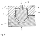
- the core member 6 is immersed into the mass to achieve complete filling of the enclosed mould cavity, as the compression of the spring means 9 forces the core 6 in direction against the bottom of the mould cavity 3. Thereby complete shells 11 are produced.
- means is arranged to control the temperature of the core member.
- This means could comprise well known temperature regulation devices such as a temperature measuring sensor connected via a wire to a control unit, which controls the regulation flow of a medium, which circulates in the channel in the holding device.
- these temperature regulation devices may be laid out in many different ways, such as comprising refrigeration or electrical heating, as long as they to the skilled person achieves an essentially constant temperature of the core member 6.
- the temperature of the core member could be controlled to be equal to or lower than 0°C, but could even be controlled to be higher than 0°C.
- An especially good quality of the shells as well as fast and efficient production has been achieved, when the temperature of the core member is controlled to be lower than around 10°C. Especially excellent results have been obtained, when the temperature of the core member is being controlled to be lower than -5°C.
- the temperature of the mould cavity may be controlled, especially to between 10°C and 30°C.
- Figure 6 discloses schematically, how the channels 19 for the temperature controlling medium are provided in the holding device 7.
- the great advantage of the invention is that it provides a very simple and robust system for transmitting heat energy from the chocolate mass 5 to the temperature controlling medium yet having an unforeseen efficiency.
- Energy is transferred from the warm chocolate 5 via the core members 6, the sliding surfaces 10 between the core members 6 and the holding device 7, into the temperature controlling medium in the at least one channel 19 in the holding device.
- the core members may be rather small (less than 10 mm in diameter) and since one holding device may easily comprise at least 100 core members this could be quite a cumbersome process. In such a tool, there would also be many possibilities for leakage of temperature controlling medium, which would then contaminate the chocolate.
- the channels 19 in the holding device may be manufactured by drilling channels in the holding device. Another way of providing the channels is also disclosed schematically in Figure 6. Grooves may be milled in two plates, the upper 12 and lower 13 part of the holding device, which may afterwards be assembled by joining their faces 14 by known methods to form the complete holding device 7.
- the channels 19 in the holding device may advantageously be provided in close distance 15 from the core members 6. The closer the channels 19 get to the core member 6 the more efficient the heat transmission from core to temperature controlling medium, the only restriction being that the material constituting the distance 15 should be strong enough.
- the channels 19 may be essentially circular or essentially rectangular.
- the walls of the channels may also be provided with ribs or depressions to increase their area.
- the cross section of the walls oblong, i.e. oval or ellipsoid as compared to circular or rectangular as compared to square, the ration of circumference to cross sectional area is increased and improved heat transmission is obtained.
- the oblong cross section should preferentially be provided close to the core members 6.
- the sliding surfaces 10 may be provided with a heat conduction compound.
- a certain tolerance between the cores and the holding device is required.
- the heat conduction compound should preferentially be of a type with a high thermal conductivity and it should have a temperature range that includes the temperatures used for the sliding surfaces.
- the compound should be compatible with the material chosen for the holding device 7 and the core members 6.
- Such heat conduction compounds are common and one suitable compound is the HEAT CONDUCTION COMPOUND from Danfoss (Denmark). Surprisingly the heat conduction compound has also been found to provide lubrication between the sliding surfaces.
- a pneumatic or hydraulic pressure is actuated between the top of the core members 6 and the opposite surfaces of the holding device 7.
- a pneumatic or hydraulic pressure is actuated between the top of the core members 6 and the opposite surfaces of the holding device 7.
- a seal may be provided on the holding device or advantageously on the core members. The great advantage of the seal is to prevent the heat conduction compound from being pressed out on to the parts of the core member that get in contact with the chocolate, and to seal the chamber above the core member efficiently to allow the build up of pneumatic or hydraulic pressure.
- seals can be used and the invention is not restricted to any specific profile or material as long as an efficient seal is provided. In many cases a simple o-ring may suffice, but it has been found advantageous to use seals with a special profile such as the four lipped seals (Quad-Ring® seal) provided by Busak+Shamban.
- the material should be chosen with due consideration of the compatibility between the heat conduction compound and the seal.
- the inventive idea also relates to core members made from a material with a high heat capacity and a high thermal conductivity such as essentially copper, essentially silver or essentially aluminum.
- a reservoir of cold can be built up in the cores and the temperature of the cores remain stable during immersion and idle periods.
- heat energy is transferred rapidly from the warmer end of the cores, i.e. the end in contact with the chocolate-like mass, to the colder parts, which are in contact with the holding device.
- the at least one core member is essentially solid.
- the top part is essentially free of channels with the purpose of controlling the temperature of the core member as is the core member itself essentially free of such channels as well.
- this inventive idea is so general that it also relates to core members that are firmly fixed to a holding device where channels for temperature controlling medium can be made in the core member.
- Experimental data show that the working temperature of an essentially solid core member can be kept lower than the working temperature of a core member in which cooling medium flows, all other factors (temperature of cooling medium, core material, dimension of core) remaining equal.
- the working temperature of an essentially solid aluminum core was 4.5°C lower than the temperature of an aluminium core with temperature controlling medium flowing in the core.
- the system comprises more than one core member 6.
- the system comprise three core members 6 guided by the same holding device 7, and three underlying mould cavities 3, 3', 3'' in a mould element 2.
- the specific numbers of mould cavities and associated core members are unlimited within this aspect of the invention.
- the at least one channel for temperature controlling medium has not been shown in this case.
- the holding device 7 comprises more than one core member, by which at least two are independently suspended from the holding device.
- every mould element normally always exhibits different depths of the specific mould cavities from the top surface 18 of the mould element.
- the differences may typically be up until around 1mm in deviation - plus (a) as depicted by the cavity 3' or minus (b) as depicted by the cavity 3'' from the actually desired depth depicted by the cavity 3.
- Such inaccuracies in the mould elements are well-known.
- each core member 6 simply automatically adapts its immersing depth in accordance herewith always obtaining, that the specific mould cavity in question becomes completely filled out with mass.
- fig. 9. it is shown, that in the closed position of the system, the core member of the cavity 3' has moved distance a further down than the core member of the first cavity 3, and that the core member of the cavity 3'' has stopped a distance b before reaching the position of the core member of the first cavity 3, yet still securing total filling of each cavity.
- a pneumatic or hydraulic pressure may advantageously be brought to the top of each core member thereby obtaining the same pressureforce for each of the shells moulded in the mould element at the same time.
- the applied pneumatic pressure could for example be lower than 10 bar.
Abstract
Description
- The present invention concerns a method for the production of fat-containing, chocolate-like masses, in particular for chocolate articles, by which an amount of liquid mass is deposited into at least one mould cavity, whereafter at least one associated core member is immersed into the mass to form the articles.
- Systems for moulding of shells of fat-containing, chocolate-like masses through immersion of a core members into the liquid mass of an associated cavity and thereby bringing the mass into the desired shape are today well-known within the prior art, and are being used extensively by the chocolate making industry.
-
EP 0 589 820 A1 (AASTED-MIKROVERK APS) describes the first commercially available method and associated apparatus of the displacing type for industrial use. It relates to a method, where the chocolate-like mass under crystallisation solidifies from the mould cavity and inwardly to form the outer shape of the shell, the temperature of the mould cavity being lower than the temperature of the tempered mass, that a cooling member having a temperature lower than 0°C is immersed into the mass and kept in the mass in a fully immersed position for a predetermined period of time. The cooling member is furthermore immersed immediately into the mass after this has been filled into the mould cavity. The associated apparatus furthermore comprises means for controlling the up- and down movement of the cooling members, as well as controlling residence times in the fully immersed position. - Generally within the present field, chocolate-like masses are suspensions of non-fat particles, such as sugar, milk powders and cocoa solids in a liquid fat phase. The fat phase in most cases comprises an extent of the genuine cocoa butter of until around 30 %, but may comprise substitutes as well. Such substitutes may be in the form of other types of fat-containing oils. Chocolate-like masses where the cocoa butter has been replaced wholly or partly by other fats, are often named commercially as compound chocolate, in which the cocoa butter has been replaced by palm-kernel oil, or corresponding oils.
- In the subsequent treatment of the ready-finished shell, the shell is frequently provided with a centre mass of a creamy or liquid food material, which differs from that of the shell. Thereafter the shell is closed either with other shell parts along the periphery of the shell or by means of a coating.
- Furthermore it is possible to join a produced shell with other types of shells immediately after being moulded, so that the finished food article being present as a hollow body e.g. in the form of eggs or figures, such as pixies and the like.
- Furthermore, it should be mentioned that manufactured shells do not have to consist of just one layer of material but may e.g. consist of several layers of chocolate-like material. For example, one shell made of dark chocolate may be provided with an interior coating of white chocolate (or vice versa) by the same method and system even before the shell moulded first leaves the mould cavity.
- The chocolate-like masses are deposited into the mould cavity in a tempered liquid state. For several decades, the technique of providing tempered chocolate-like masses has been well known to the persons skilled within the art of chocolate-making. Chocolate-like mass being heated to 40-50°C enters the process of tempering in which the mass in cooled down to around 27-32°C, whereby crystallisation is initiated. Thereafter, the chocolate-like mass is re-heated, normally not more than 2°C providing the ready-tempered chocolate-like mass with a content of stable β crystals in an amount lesser than 5 %. Thereby lower melting crystals are re-melted, so that only stable crystals remain in the ready-tempered mass. Such a process is for example performed by the AMK-tempering machines provided by Aasted-Mikroverk ApS, Denmark.
- The quality of the ready-moulded chocolate shells has always been determined firstly by the state of the tempered chocolate mass. The skilled person knew that good flavour and mouth feeling chocolate, high gloss, high resistance to fat bloom as well as enhanced resistance to warm or heat was the consequence of the optimum tempering state, in which the liquid chocolate comprises only stable β crystals, especially small crystals before being deposited into the mould. However, before the invention of
EP 0 589 820 B1 (AASTED-MIKROVERK APS), the skilled person thought that the setting of the deposited chocolate in the mould should be gentle and time consuming to an extent of often ½ - 1 hour before the moulded shell could be released from the mould cavity. By the invention ofEP 0 589 820 B1 this prejudice was turned upside down, thereby discovering a method by which the deposited tempered chocolate was set rapidly e.g. typically within 10 seconds providing tremendous fast production rates for chocolate making industry. - WO 95/32633 (AASTED-MIKROVERK APS) describes a method and a system of the displacing type, by which an engagement ring is mounted peripherally around the cooling member by a press-fit or by threaded engagement. The engagement ring comprises at least one peripherally extending recess defining the moulded shell rim to compensate for inaccuracies in the deposited amount of chocolate. By depositing larger amounts of tempered chocolate-like mass into the mould cavity than the volume being available when the cooling member is fully immersed, liquid mass will escape at the upper surface of the mould cavity and be taken up in the recess. Thereby, complete articles with a well-defined rim can be manufactured.
- WO 98/52425 (KMB PRODUCTIONS AG) discloses a system for moulding of shells primarily for moulding of chocolate shells. This system comprises multiple core members firmly fixed to a holding device. Cooling of the core members is provided through channels in the core members and in the plate, on which they are firmly secured. Since the core members are firmly fixed it is not possible to lower the individual core members to different depths relative to the plate, on which they are secured.
- EP 0 715 813 (GEBR. BINDLER) discloses a similar system for moulding of chocolate articles, especially for chocolate shells, through displacement of the chocolate mass in a mould by immersion of a core member. The disclosed embodiments all have a multiplicity of core members firmly fixed to the same holding device. As in the above WO 98/524255 publication, the system has no way of compensating for inaccuracies in the dosage of chocolate or for differences in the depth of the individual mould cavities. Thus, if for some reason, one of the mould cavities of a mould element is clogged and the associated core cannot be immersed further than the depth of the obstruction, all the fixed cores will be halted and consequently all the shells of that mould element will be incomplete.
- In practise, it is not possible to manufacture mould elements where all the mould cavities have exactly the same size, especially depth. Furthermore, it is not possible to achieve exact dosage of the chocolate when it is deposited into the mould cavities. Consequently, when several core members that are firmly fixed to the same holding device are lowered into the mould cavities the resulting displacement of chocolate will give rise to shells of different size.
- The purpose of the present invention is to provide a simple, robust, flexible, and efficient system for moulding chocolate articles.
- The present invention relates to a system for the production of shells of fat-containing, chocolate-like masses, in particular for chocolate articles, comprising at least one mould cavity to receive the mass, at least one core member to be immersed into the mass, a holding device adapted to engage the at least one core member, wherein at least one channel is provided in the holding device, in which temperature controlling medium flows, and whereby the core members have sliding surfaces that are supported by opposite sliding surfaces of the holding device.
- The great advantage of the invention is that it provides a very simple and robust system for transmitting heat energy from the chocolate mass to the temperature controlling medium yet having an unforeseen efficiency. Energy is transferred from the warm chocolate via the core members, the sliding surfaces between the core members and the holding device, into the temperature controlling medium in the at least one channel in the holding device. Thereby is avoided the need for bringing the temperature controlling medium in direct contact with the core members, which process would require the manufacture of channels in the core members and providing some sort of flexible connection with each individual core member to bring the temperature controlling medium across the sliding surfaces. Since the core members in some cases may be rather small (less than 10 mm in diameter) and since one holding device may easily comprise at least 100 core members this could be quite a cumbersome process. In such a tool, there would also be many possibilities for leakage of temperature controlling medium, which would then contaminate the chocolate.
- Another advantage of the invention is that the cores are moveable in relation to the holding device by means of the opposite sliding surfaces. Thereby the cores can be lowered to many different depths in relation to the holding device and may for instance be adjusted to articles having different thickness without reducing the efficiency of heat transmission. The sliding surfaces may preferentially be essentially vertical.
- Furthermore, the at least one core member may be countersunk into the holding device. Hereby, the sliding surfaces that provide the heat transmission from core to holding device constitute a larger part of the surface of the cores and very efficient heat transmission is achieved. An additional advantage of this embodiment is improved precision in the movement of the core in relation to the holding device due to the larger sliding surfaces.
- According to a preferred embodiment, the system is provided with means adapted to control the temperature of the at least one core member. Such means comprises the temperature controlling medium and known type of means to control its temperature and/or flow. Such means can be laid out in many different ways and the invention is not restricted to any specific means as long as an essential constant temperature of the at least one core is achieved.
- According to a particularly preferred embodiment, the at least one channel is arranged in a part of the holding device in close distance to the at least one core member. Close distance could for instance be less than 10 mm, the only restriction being that the part of the holding device that separates the channel from the core members remains strong enough. Hereby, an improved heat transmission from the core member to the temperature controlling medium is obtained, since the distance from the core member to the channel is very short.
- The cross section of the at least one channel may be laid out in different ways, such as essentially circular or essentially rectangular. Thus, the walls of the channels may have fins or ribs or various depressions that would serve to increase the area of the walls, thereby improving the heat transmission.
- By further making the cross section oblong, i.e. oval or ellipsoid in contrast to circular and rectangular in contrast to square, the contact surface of the channel is increased relative to its cross sectional area. This embodiment allows even higher transmission of heat energy from the holding device to the temperature controlling medium. The longer side of the oblong cross section of the at least one channel may preferentially face towards the at least one core member.
- The sliding surfaces of the core member and holding device may also be provided with a heat-conduction compound, said heat-conduction compound being adapted to improve the transfer of heat from the independently suspended core members to the holding device. In order to allow the cores to slide, a certain tolerance between the cores and the holding device is required. By thus filling out this tolerance with a heat conduction compound, the heat transmission is improved greatly. Surprisingly the heat conduction compound has also been found to provide lubrication between the sliding surfaces.
- The inventive idea also relates to core members made from a material with a high heat capacity and a high thermal conductivity such as essentially copper, essentially silver or essentially aluminium. Hereby two advantages are obtained. Firstly, a reservoir of cold can be built up in the cores and the temperature of the cores remain stable during immersion and idle periods. Secondly, heat energy is transferred rapidly from the warmer end of the cores, i.e. the end in contact with the chocolate-like mass, to the colder parts, which are in contact with the holding device.
- According to an especially preferred embodiment the at least one core member is essentially solid. Thereby, an especially large cold reservoir can be built up in the cores which results in even more efficient cooling and thereby increased production speed of the whole system.
- Finally, the at least one core member may be independently suspended from a holding device. By independent is meant that the suspension of one core member cannot affect the suspension of the other cores. Similarly, the suspension of one single core is not affected by the suspension of the other cores.
- Hereby the additional advantage is obtained that the individual core members can be lowered to different depths to make all articles in a given mould element complete, irrespective of variations in the actual depth of the mould cavities or in the amount of deposited chocolate without affecting the efficiency of heat transmission. This provides unforeseen flexibility of the moulding system, which is capable of compensating for variations that are far greater than those actually experienced. If one mould cavity in a mould element contains significantly more liquid chocolate than the others, the core member associated with this mould cavity will simply stop its vertical travel before the other core members and due to the independence of the suspension the continued vertical travel of the remaining core members will not be affected. If on the other hand, significantly less chocolate has been deposited into a particular mould, the associated core will continue its vertical travel, independently of the other cores, to the point where this shell is also complete. The same will apply in case of a significantly deeper or less deep mould cavity. The bottom part of the shells may vary slightly in thickness.
- The invention is explained more fully below with reference to particularly preferred embodiments as well as the drawings.
- Figure 1
- is a schematic view of the steps performed to reach a packaged shell product.
- Figure 2
- is a schematic view of a turning point of an endless carrier for the mould elements, carried through the steps of Figure 1.
- Figure 3
- is a sectional view along A-A of the mould element of Figure 2.
- Figure 4
- is an embodiment shown as a lateral, schematic, cross-sectional view through one of the core members comprising sliding surfaces and an associated, underlying mould cavity filled with chocolate.
- Figure 5
- is a view of the same in a closed position, with the core member fully immersed into the chocolate mass.
- Figure 6
- is a schematic, cross-sectional view through a holding device comprising by an upper and lower part, providing the channels for temperature controlling medium, and carrying several solid core members with sliding surfaces.
- Figure 7
- is a schematic, cross sectional view through a holding device carrying several essentially solid core members and comprising a channel for temperature controlling medium, a heat conduction compound on the sliding surfaces.
- Figure 8
- is a lateral, schematic, cross-sectional view through a holding device, carrying several independently suspended core members and underlying mould cavities, which are now filled with liquid mass.
- Figure 9
- is a view of the same in a closed position.
- Steps to be performed for reaching a packed shell product is schematically disclosed in fig. 1.
- Between two
turning points 4 anendless carrier belt 1 normally carriesmould elements 2 through the depositing section, the moulding section, the cooling section, the demoulding section and finally to the packaging section. Thereafter, theendless carrier belt 1 returns themould elements 2 to the depositing section. Themoulding elements 2 may comprise one or evenseveral mould cavities 3, as depicted in fig. 2 and 3. - Furthermore, it should be mentioned, that the fig. 1-3 disclose, that mould elements are moved continuously through the specific sections, such as the moulding section. In the moulding section, the moulding elements may be kept stationary when the associated core members are immersed, or the core members may be moved synchronously with the mould elements within the moulding section. Means for achieving such movements are well known to the skilled person within the art of chocolate making.
- As described in
EP 0 589 820 B1 (AASTED-MIKROVER APS) such systems comprise means for controlling the up and down movement of the core members as well as means for controlling the residence times of the core members in the fully immersed position, by the present invention especially to a predetermined time period. Furthermore, by the present invention, the residence times are typically lower than 60 seconds, though the invention is not restricted to such limitation. The residence times are more preferably lower than 20 seconds and are found to be especially expedient when between 0.1 and 5 seconds. - In the tempering section, the fat-containing, chocolate-like mass is normally tempered to a temperature of around 27-34°C having a content of stable β crystals. However, the actual temperatures as well as contents of stable β crystals depend on the choice of the skilled person for the chocolate-like mass in question. The tempered chocolate-like mass is delivered to the depositing section, in which the liquid mass is deposited into the
mould cavity 3. In the moulding section to follow, a core member is immersed into the mass and the shell is actually moulded. Thereafter, a cooling section may follow, as well as a section for demoulding the shell from the mould, and finally a packaging section, in which the shells are packed for delivery. The systems of the present invention are subject of the moulding section. - It should be mentioned, that in the remaining drawings of this description, it is disclosed that the tempered
mass 5 already has been deposited into themould cavities 3, 3', 3''. - The basic structure of the moulding tool is disclosed schematically in Figure 4 and 5. For clarity, these Figures do not disclose the channel for the temperature controlling medium which should be imagined in the
holding device 7. As disclosed in Figure 4 thecore member 6 has slidingsurfaces 10 adapted to support opposite sliding surfaces of the holdingdevice 7, thereby providing guidance and a means for transmitting heat from thecore 6 to theholding device 7. The geometric form of the part of the core that comprises the sliding surfaces could be laid out in very many different ways. The cross section could be essentially circular or essentially rectangular, but it should be stressed that the invention is not restricted to any specific geometric forms. Any form can be used as long as the surfaces are capable of sliding and as long as heat transmission across the sliding surfaces is possible. - Similarly, the distance that the
core member 6 projects into the holdingdevice 7 is not limited to any specific interval. The length of the sliding surfaces may typically be between 5 and 100 mm but other lengths may also be used. Again, it is only important that the surfaces can actually slide, transmit heat, and guide the movement of the core. - By this embodiment, the
core member 6 is axially movably suspended from a holdingdevice 7, which controls the movements of thecore 6. By this embodiment, the closure means constitutes part of the holdingdevice 7. Thecore member 6 is guided axially in relation to theholding device 7 by means of a known type ofslide guidance 8. The suspension may typically comprise compressible spring means 9 of any kind. However, a pneumatic or hydraulic pressure effected at the top surface of the core member may create the appropriate suspension effect as well, either alone or in combination with the mentioned spring means 9. - It should be noted, that though not disclosed, the embodiment of fig 4-9 may comprise a separate mould cavity closure ring suspended from the holding
device 7. - By moving the
core member 6 down into themass 5, the holdingdevice 7 itself or the possibly intermediary closure ring comes to secure engagement with the upper surface of themould element 2 as disclosed in fig. 5. By doing so, thecore member 6 is immersed into the mass to achieve complete filling of the enclosed mould cavity, as the compression of the spring means 9 forces thecore 6 in direction against the bottom of themould cavity 3. Therebycomplete shells 11 are produced. - According to a particularly preferred embodiment of the invention, means is arranged to control the temperature of the core member. This means could comprise well known temperature regulation devices such as a temperature measuring sensor connected via a wire to a control unit, which controls the regulation flow of a medium, which circulates in the channel in the holding device. However, these temperature regulation devices may be laid out in many different ways, such as comprising refrigeration or electrical heating, as long as they to the skilled person achieves an essentially constant temperature of the
core member 6. The temperature of the core member could be controlled to be equal to or lower than 0°C, but could even be controlled to be higher than 0°C. An especially good quality of the shells as well as fast and efficient production has been achieved, when the temperature of the core member is controlled to be lower than around 10°C. Especially excellent results have been obtained, when the temperature of the core member is being controlled to be lower than -5°C. - Even the temperature of the mould cavity may be controlled, especially to between 10°C and 30°C. Thereby it has astonishingly been discovered, that a smooth outer surface of the shells is obtained without having any shrinks or depressions, such as the so called "Saturn" rings.
- Figure 6 discloses schematically, how the
channels 19 for the temperature controlling medium are provided in theholding device 7. The great advantage of the invention is that it provides a very simple and robust system for transmitting heat energy from thechocolate mass 5 to the temperature controlling medium yet having an unforeseen efficiency. Energy is transferred from thewarm chocolate 5 via thecore members 6, the slidingsurfaces 10 between thecore members 6 and the holdingdevice 7, into the temperature controlling medium in the at least onechannel 19 in the holding device. Thereby is avoided the need for bringing the temperature controlling medium in direct contact with the core members, which process would require the manufacture of channels in the core members and providing some sort of flexible connection with each individual core member to bring the temperature controlling medium across the sliding surfaces. Since the core members may be rather small (less than 10 mm in diameter) and since one holding device may easily comprise at least 100 core members this could be quite a cumbersome process. In such a tool, there would also be many possibilities for leakage of temperature controlling medium, which would then contaminate the chocolate. - The
channels 19 in the holding device may be manufactured by drilling channels in the holding device. Another way of providing the channels is also disclosed schematically in Figure 6. Grooves may be milled in two plates, the upper 12 and lower 13 part of the holding device, which may afterwards be assembled by joining theirfaces 14 by known methods to form thecomplete holding device 7. - The
channels 19 in the holding device may advantageously be provided inclose distance 15 from thecore members 6. The closer thechannels 19 get to thecore member 6 the more efficient the heat transmission from core to temperature controlling medium, the only restriction being that the material constituting thedistance 15 should be strong enough. - According to another embodiment, the
channels 19 may be essentially circular or essentially rectangular. The walls of the channels may also be provided with ribs or depressions to increase their area. By making the cross section of the walls oblong, i.e. oval or ellipsoid as compared to circular or rectangular as compared to square, the ration of circumference to cross sectional area is increased and improved heat transmission is obtained. The oblong cross section should preferentially be provided close to thecore members 6. - As disclosed schematically in Figure 7, the sliding
surfaces 10 may be provided with a heat conduction compound. In order to allow the cores to slide, a certain tolerance between the cores and the holding device is required. By thus filling out this tolerance with a heat conduction compound, the heat transmission is improved greatly. The heat conduction compound should preferentially be of a type with a high thermal conductivity and it should have a temperature range that includes the temperatures used for the sliding surfaces. In addition, the compound should be compatible with the material chosen for the holdingdevice 7 and thecore members 6. Such heat conduction compounds are common and one suitable compound is the HEAT CONDUCTION COMPOUND from Danfoss (Denmark). Surprisingly the heat conduction compound has also been found to provide lubrication between the sliding surfaces. - In some embodiments, a pneumatic or hydraulic pressure is actuated between the top of the
core members 6 and the opposite surfaces of the holdingdevice 7. Such an embodiment is disclosed schematically in Figure 7 where the pressure is provided through achannel 17. In these embodiments, a seal may be provided on the holding device or advantageously on the core members. The great advantage of the seal is to prevent the heat conduction compound from being pressed out on to the parts of the core member that get in contact with the chocolate, and to seal the chamber above the core member efficiently to allow the build up of pneumatic or hydraulic pressure. - Very many different embodiments of the seal can be used and the invention is not restricted to any specific profile or material as long as an efficient seal is provided. In many cases a simple o-ring may suffice, but it has been found advantageous to use seals with a special profile such as the four lipped seals (Quad-Ring® seal) provided by Busak+Shamban. The material should be chosen with due consideration of the compatibility between the heat conduction compound and the seal.
- The inventive idea also relates to core members made from a material with a high heat capacity and a high thermal conductivity such as essentially copper, essentially silver or essentially aluminum. Hereby two advantages are obtained. Firstly, a reservoir of cold can be built up in the cores and the temperature of the cores remain stable during immersion and idle periods. Secondly, heat energy is transferred rapidly from the warmer end of the cores, i.e. the end in contact with the chocolate-like mass, to the colder parts, which are in contact with the holding device.
- According to an especially preferred embodiment the at least one core member is essentially solid. Thereby, an especially large cold reservoir can be built up in the cores which results in even more efficient cooling and thereby increased production speed of the whole system.
- Preferentially, the top part is essentially free of channels with the purpose of controlling the temperature of the core member as is the core member itself essentially free of such channels as well.
- Actually, this inventive idea is so general that it also relates to core members that are firmly fixed to a holding device where channels for temperature controlling medium can be made in the core member. Experimental data show that the working temperature of an essentially solid core member can be kept lower than the working temperature of a core member in which cooling medium flows, all other factors (temperature of cooling medium, core material, dimension of core) remaining equal. For one specific core dimension, where the temperature of the temperature controlling medium was set to -12 to -14°C, the working temperature of an essentially solid aluminum core was 4.5°C lower than the temperature of an aluminium core with temperature controlling medium flowing in the core.
- By the embodiment of fig. 8 and 9 the system comprises more than one
core member 6. By the disclosed example the system comprise threecore members 6 guided by thesame holding device 7, and threeunderlying mould cavities 3, 3', 3'' in amould element 2. However, the specific numbers of mould cavities and associated core members are unlimited within this aspect of the invention. For clarity, the at least one channel for temperature controlling medium has not been shown in this case. - Important is, that the holding
device 7 comprises more than one core member, by which at least two are independently suspended from the holding device. Thereby is obtained the unexpected advantage, that essentially the same predetermined pressureforce may be obtained in everymould cavity 3, 3'' 3'' whatever the actual depth of the specific cavity may be under theupper surface 18 of themould element 2. By achieving this, one is sure, that the deposited amount of mass in everycavity 3, 3', 3'' of the mould element completely fills out the specific mould cavity when all thecore members 6 are immersed at the same time as depicted in fig. 9. - As schematically shown in fig. 8, every mould element normally always exhibits different depths of the specific mould cavities from the
top surface 18 of the mould element. The differences may typically be up until around 1mm in deviation - plus (a) as depicted by the cavity 3' or minus (b) as depicted by the cavity 3'' from the actually desired depth depicted by thecavity 3. Such inaccuracies in the mould elements are well-known. - Furthermore, the actually deposited amount of mass in each cavity becomes more or less irrelevant as each
core member 6 simply automatically adapts its immersing depth in accordance herewith always obtaining, that the specific mould cavity in question becomes completely filled out with mass. In fig. 9. it is shown, that in the closed position of the system, the core member of the cavity 3' has moved distance a further down than the core member of thefirst cavity 3, and that the core member of the cavity 3'' has stopped a distance b before reaching the position of the core member of thefirst cavity 3, yet still securing total filling of each cavity. By the prior art where the core members were all fixed to the holding device the positions of the immersed core members always remained the same in relation to the mould cavities, what ever the actual depth of the cavity may be or the deposited amount of mass may be. The result was, that unacceptable variations in the appearance, the thickness as well as homogeneity occurred. - At disclosed by the
channels 17, a pneumatic or hydraulic pressure may advantageously be brought to the top of each core member thereby obtaining the same pressureforce for each of the shells moulded in the mould element at the same time. The applied pneumatic pressure could for example be lower than 10 bar. - By the embodiment of fig. 8, 9 an especially fast and productive system for shell making is available, yet providing an unforeseen high quality of the complete batch of shells produced.
Claims (21)
- A system for the production of shells of fat-containing, chocolate-like masses, in particular for chocolate articles,comprising at least one mould cavity (3, 3', 3'') to receive the mass (5),at least one core member (6, 6', 6'') to be immersed into the mass,a holding device (7) adapted to engage the at least one core member,
wherein at least one channel (19) is provided in the holding device, in which temperature controlling medium flows, and
whereby the at least one core member has sliding surfaces (10) that are supported by opposite sliding surfaces (10) of the holding device. - A system according to claim 1, whereby the sliding surfaces (10) are essentially vertical.
- A system according to claim 1, whereby the at least one core member (6, 6', 6'') is countersunk into the holding device (7).
- A system according to claim 1, comprising means adapted to control the temperature of the at least one core member (6, 6', 6'').
- A system according to claim 1, whereby the at least one channel (19) is arranged in a part of the holding device (7) in close distance (15) to the at least one core member (6, 6', 6'').
- A system according to claim 1, whereby the cross section of the at least one channel (19) is essentially circular in at least part of the channel.
- A system according to claim 1, whereby the cross section of the at least one channel (19) is essentially rectangular in at least part of the channel.
- A system according to claim 1, whereby the cross section of the at least one channel (19) is oblong in at least part of the channel.
- A system according to claim 1, whereby the longer side of the oblong cross section of the at least one channel (19) faces towards the at least one core member 86, 6', 6'').
- A system according to claim 1, comprising a heat-conduction compound at the sliding surfaces (10),
said heat-conduction compound being adapted to improve the transmission of heat from the at least one core member (6, 6', 6'') to the holding device (7). - A system according to claim 1, comprising core members (6, 6', 6'') made essentially from copper.
- A system according to claim 1, comprising core members (6, 6', 6'') made essentially from silver.
- A system according to claim 1, comprising core members (6, 6', 6'') made essentially from aluminium.
- A system according to claim 1, whereby the at least one core member (6, 6', 6'') is essentially solid.
- A system according to claim 1, whereby the at least one core member (6, 6', 6'') is essentially free from channels.
- A system according to claim 1, whereby more than one core member (6, 6', 6'') is independently suspended from a holding device (7).
- A part of a system for the production of shells of fat-containing, chocolate like masses, in particular for chocolate articles,which part comprises a holding device (7) with at least one channel (19), in which temperature controlling medium flows,
whereby the holding device has sliding surfaces (10) adapted to support opposite sliding surfaces (10) of at least one core member (6, 6', 6''). - A part of a system according to claim 17, comprising means adapted to provide independent suspension of more than one core member (6, 6', 6'').
- A part of a system for the production of shells of fat-containing, chocolate like masses, in particular for chocolate articles,which part comprises a core member (6, 6', 6'') adapted to engage with a holding device (7)
whereby the core member has sliding surfaces (10) adapted to be supported by opposite sliding surfaces (10) of the holding device. - A part of a system according to claim 19, whereby the core member (6, 6', 6'') is essentially solid.
- A part of a system according to claim whereby the core member (6, 6', 6'') is essentially free from channels.
Priority Applications (1)
| Application Number | Priority Date | Filing Date | Title |
|---|---|---|---|
| EP19990200464 EP0923876B1 (en) | 1998-11-02 | 1999-02-19 | Apparatus for the production of shells of fat-containing, chocolate-like masses |
Applications Claiming Priority (5)
| Application Number | Priority Date | Filing Date | Title |
|---|---|---|---|
| EP98203693A EP0920810B1 (en) | 1998-11-02 | 1998-11-02 | System for the production of shells of fat-containing, chocolate-like masses under pressure build-up |
| EP98203693 | 1998-11-02 | ||
| EP98203783 | 1998-11-09 | ||
| EP19980203783 EP0914774B1 (en) | 1998-11-09 | 1998-11-09 | Apparatus for the production of shells of fat-containing chocolate-like masses |
| EP19990200464 EP0923876B1 (en) | 1998-11-02 | 1999-02-19 | Apparatus for the production of shells of fat-containing, chocolate-like masses |
Publications (2)
| Publication Number | Publication Date |
|---|---|
| EP0923876A1 true EP0923876A1 (en) | 1999-06-23 |
| EP0923876B1 EP0923876B1 (en) | 2001-05-09 |
Family
ID=27239417
Family Applications (2)
| Application Number | Title | Priority Date | Filing Date |
|---|---|---|---|
| EP19990200463 Expired - Lifetime EP0925720B1 (en) | 1998-11-02 | 1999-02-19 | Apparatus comprising independently suspended core members for the production of shells of fat-containing, chocolate-like masses |
| EP19990200464 Expired - Lifetime EP0923876B1 (en) | 1998-11-02 | 1999-02-19 | Apparatus for the production of shells of fat-containing, chocolate-like masses |
Family Applications Before (1)
| Application Number | Title | Priority Date | Filing Date |
|---|---|---|---|
| EP19990200463 Expired - Lifetime EP0925720B1 (en) | 1998-11-02 | 1999-02-19 | Apparatus comprising independently suspended core members for the production of shells of fat-containing, chocolate-like masses |
Country Status (1)
| Country | Link |
|---|---|
| EP (2) | EP0925720B1 (en) |
Cited By (8)
| Publication number | Priority date | Publication date | Assignee | Title |
|---|---|---|---|---|
| EP1346642A1 (en) * | 2002-03-20 | 2003-09-24 | Aasted-Mikroverk Aps | Apparatus for making chocolate shells |
| EP1346644A1 (en) * | 2002-03-20 | 2003-09-24 | Aasted-Mikroverk Aps | Method of making chocolate covering layers |
| EP1346645A1 (en) * | 2002-03-20 | 2003-09-24 | Aasted-Mikroverk Aps | Apparatus for making chocolade covering layers |
| EP1396192A1 (en) * | 2002-09-06 | 2004-03-10 | Aasted-Mikroverk Aps | Apparatus for pressing edible articles |
| EP1396191A1 (en) * | 2002-09-06 | 2004-03-10 | Aasted-Mikroverk Aps | Apparatus for pressing edible articles |
| EP1413205A1 (en) * | 2002-10-25 | 2004-04-28 | Kraft Foods R & D, Inc. | Injection molding of fat-containing confectionery mass |
| WO2004034800A1 (en) * | 2002-10-21 | 2004-04-29 | C & G S.P.A. | Device and method for controlling the condensate and/or frost formation in chocolate shell moulding |
| EP1430784A1 (en) * | 2002-12-20 | 2004-06-23 | Aasted-Mikroverk Aps | Apparatus for pressing edible articles, such as of chocolate |
Families Citing this family (5)
| Publication number | Priority date | Publication date | Assignee | Title |
|---|---|---|---|---|
| ATE248523T1 (en) * | 2000-04-28 | 2003-09-15 | Kraft Foods R & D Inc | METHOD FOR PRODUCING CHOCOLATE BY SUPER COOLING AND PRESS MOLDING |
| KR20020060512A (en) * | 2001-01-11 | 2002-07-18 | 한수길 | Process for making chocolate with the use of frozen mould |
| DE102005015052A1 (en) * | 2005-03-31 | 2006-10-05 | Bühler AG | Device for producing cup-like shaped consumer goods |
| EP2018811B1 (en) * | 2007-07-26 | 2011-06-22 | Winkler und Dünnebier Süsswarenmaschinen GmbH | Method and moulding station for moulding confectionery shells |
| CN106231914B (en) | 2014-05-06 | 2021-07-16 | 布勒股份公司 | Die plate with molded stop |
Citations (4)
| Publication number | Priority date | Publication date | Assignee | Title |
|---|---|---|---|---|
| AU532845B2 (en) * | 1979-11-20 | 1983-10-13 | Albert Fradin | Moulding slow setting material |
| EP0589820A1 (en) * | 1992-09-23 | 1994-03-30 | Aasted-Mikroverk Aps | A method and device for moulding of chocolate articles |
| EP0715813A1 (en) * | 1994-12-08 | 1996-06-12 | Gebr. Bindler Maschinenfabrik GmbH & Co. KG | Process and apparatus for making chocolate articles, particularly shells for chocolate hollow articles |
| DE19720844C1 (en) * | 1997-05-17 | 1998-08-13 | Kmb Produktions Ag | Food manufacturing process |
Family Cites Families (3)
| Publication number | Priority date | Publication date | Assignee | Title |
|---|---|---|---|---|
| US5558895A (en) * | 1992-02-14 | 1996-09-24 | Gradual Pty Ltd. | Molding process and apparatus |
| DK171697B1 (en) * | 1994-05-31 | 1997-03-24 | Aasted Mikroverk Aps | Plants for the production of shells of liquid, temperate and fatty chocolate-like mass, shells made therefrom, foodstuffs comprising said shells and the use of said shells as constituents of foodstuffs |
| AUPO066196A0 (en) * | 1996-06-25 | 1996-07-18 | Gradual Pty Ltd | Above mould moulding apparatus and method |
-
1999
- 1999-02-19 EP EP19990200463 patent/EP0925720B1/en not_active Expired - Lifetime
- 1999-02-19 EP EP19990200464 patent/EP0923876B1/en not_active Expired - Lifetime
Patent Citations (4)
| Publication number | Priority date | Publication date | Assignee | Title |
|---|---|---|---|---|
| AU532845B2 (en) * | 1979-11-20 | 1983-10-13 | Albert Fradin | Moulding slow setting material |
| EP0589820A1 (en) * | 1992-09-23 | 1994-03-30 | Aasted-Mikroverk Aps | A method and device for moulding of chocolate articles |
| EP0715813A1 (en) * | 1994-12-08 | 1996-06-12 | Gebr. Bindler Maschinenfabrik GmbH & Co. KG | Process and apparatus for making chocolate articles, particularly shells for chocolate hollow articles |
| DE19720844C1 (en) * | 1997-05-17 | 1998-08-13 | Kmb Produktions Ag | Food manufacturing process |
Cited By (11)
| Publication number | Priority date | Publication date | Assignee | Title |
|---|---|---|---|---|
| EP1346642A1 (en) * | 2002-03-20 | 2003-09-24 | Aasted-Mikroverk Aps | Apparatus for making chocolate shells |
| EP1346644A1 (en) * | 2002-03-20 | 2003-09-24 | Aasted-Mikroverk Aps | Method of making chocolate covering layers |
| EP1346645A1 (en) * | 2002-03-20 | 2003-09-24 | Aasted-Mikroverk Aps | Apparatus for making chocolade covering layers |
| EP1396192A1 (en) * | 2002-09-06 | 2004-03-10 | Aasted-Mikroverk Aps | Apparatus for pressing edible articles |
| EP1396191A1 (en) * | 2002-09-06 | 2004-03-10 | Aasted-Mikroverk Aps | Apparatus for pressing edible articles |
| US6843168B2 (en) | 2002-09-06 | 2005-01-18 | Aasted-Mikroverk Aps | Apparatus for pressing edible articles |
| US6845708B2 (en) | 2002-09-06 | 2005-01-25 | Aasted-Mikroverk Aps | Apparatus for pressing edible articles |
| WO2004034800A1 (en) * | 2002-10-21 | 2004-04-29 | C & G S.P.A. | Device and method for controlling the condensate and/or frost formation in chocolate shell moulding |
| US7845929B2 (en) | 2002-10-21 | 2010-12-07 | Carle & Montanari S.P.A. | Device and method for controlling the condensate and/or frost formation in chocolate shell production |
| EP1413205A1 (en) * | 2002-10-25 | 2004-04-28 | Kraft Foods R & D, Inc. | Injection molding of fat-containing confectionery mass |
| EP1430784A1 (en) * | 2002-12-20 | 2004-06-23 | Aasted-Mikroverk Aps | Apparatus for pressing edible articles, such as of chocolate |
Also Published As
| Publication number | Publication date |
|---|---|
| EP0925720A1 (en) | 1999-06-30 |
| EP0925720B1 (en) | 2001-09-12 |
| EP0923876B1 (en) | 2001-05-09 |
Similar Documents
| Publication | Publication Date | Title |
|---|---|---|
| EP0920810B1 (en) | System for the production of shells of fat-containing, chocolate-like masses under pressure build-up | |
| EP0945069B1 (en) | Apparatus for the production of shells of fat-containing, chocolate-like masses | |
| EP0923876B1 (en) | Apparatus for the production of shells of fat-containing, chocolate-like masses | |
| EP0914774B1 (en) | Apparatus for the production of shells of fat-containing chocolate-like masses | |
| US5635230A (en) | Method and apparatus for producing shells of fat-containing, masses and food articles produced thereby | |
| AU2001263077B2 (en) | Methods and apparatus for continuously molding chocolate and products made thereby | |
| AU9710098A (en) | Method for making food article | |
| AU2001263077A1 (en) | Methods and apparatus for continuously molding chocolate and products made thereby | |
| CA2611267C (en) | A process for making foodstuff products, and a foodstuff product thus made | |
| US20030232113A1 (en) | Method and apparatus for making chocolate covering layers | |
| US6843168B2 (en) | Apparatus for pressing edible articles | |
| EP1346641B1 (en) | Method of making chocolate shells | |
| EP1346645B1 (en) | Apparatus for making chocolate covering layers | |
| EP1714559B1 (en) | Apparatus for making chocolate articles on a conveyor web | |
| EP1396192A1 (en) | Apparatus for pressing edible articles | |
| EP1346643A1 (en) | Method of making chocolate shells | |
| EP1346644B1 (en) | Method of making chocolate covering layers | |
| US20030235641A1 (en) | Method and apparatus for making chocolate shells | |
| EP1346642B1 (en) | Apparatus for making chocolate shells | |
| EP1430784A1 (en) | Apparatus for pressing edible articles, such as of chocolate | |
| JPH1056970A (en) | Molding of confection material containing fat | |
| MXPA99006489A (en) | Method of shaping chocolate products |
Legal Events
| Date | Code | Title | Description |
|---|---|---|---|
| PUAI | Public reference made under article 153(3) epc to a published international application that has entered the european phase |
Free format text: ORIGINAL CODE: 0009012 |
|
| AK | Designated contracting states |
Kind code of ref document: A1 Designated state(s): BE CH DE DK FR GB IT LI NL |
|
| AX | Request for extension of the european patent |
Free format text: AL;LT;LV;MK;RO;SI |
|
| DET | De: translation of patent claims | ||
| 17P | Request for examination filed |
Effective date: 19991123 |
|
| AKX | Designation fees paid |
Free format text: AT BE CH CY DE DK ES FI LI |
|
| RBV | Designated contracting states (corrected) |
Designated state(s): BE CH DE DK FR GB IT LI NL |
|
| 17Q | First examination report despatched |
Effective date: 20000717 |
|
| GRAG | Despatch of communication of intention to grant |
Free format text: ORIGINAL CODE: EPIDOS AGRA |
|
| GRAG | Despatch of communication of intention to grant |
Free format text: ORIGINAL CODE: EPIDOS AGRA |
|
| GRAH | Despatch of communication of intention to grant a patent |
Free format text: ORIGINAL CODE: EPIDOS IGRA |
|
| GRAH | Despatch of communication of intention to grant a patent |
Free format text: ORIGINAL CODE: EPIDOS IGRA |
|
| GRAA | (expected) grant |
Free format text: ORIGINAL CODE: 0009210 |
|
| AK | Designated contracting states |
Kind code of ref document: B1 Designated state(s): BE CH DE DK FR GB IT LI NL |
|
| PG25 | Lapsed in a contracting state [announced via postgrant information from national office to epo] |
Ref country code: NL Free format text: LAPSE BECAUSE OF FAILURE TO SUBMIT A TRANSLATION OF THE DESCRIPTION OR TO PAY THE FEE WITHIN THE PRESCRIBED TIME-LIMIT Effective date: 20010509 Ref country code: IT Free format text: LAPSE BECAUSE OF FAILURE TO SUBMIT A TRANSLATION OF THE DESCRIPTION OR TO PAY THE FEE WITHIN THE PRESCRIBED TIME-LIMIT;WARNING: LAPSES OF ITALIAN PATENTS WITH EFFECTIVE DATE BEFORE 2007 MAY HAVE OCCURRED AT ANY TIME BEFORE 2007. THE CORRECT EFFECTIVE DATE MAY BE DIFFERENT FROM THE ONE RECORDED. Effective date: 20010509 Ref country code: FR Free format text: LAPSE BECAUSE OF FAILURE TO SUBMIT A TRANSLATION OF THE DESCRIPTION OR TO PAY THE FEE WITHIN THE PRESCRIBED TIME-LIMIT Effective date: 20010509 Ref country code: BE Free format text: LAPSE BECAUSE OF FAILURE TO SUBMIT A TRANSLATION OF THE DESCRIPTION OR TO PAY THE FEE WITHIN THE PRESCRIBED TIME-LIMIT Effective date: 20010509 |
|
| RIN1 | Information on inventor provided before grant (corrected) |
Inventor name: AASTED, LARS |
|
| REG | Reference to a national code |
Ref country code: CH Ref legal event code: EP |
|
| REF | Corresponds to: |
Ref document number: 69900099 Country of ref document: DE Date of ref document: 20010613 |
|
| PG25 | Lapsed in a contracting state [announced via postgrant information from national office to epo] |
Ref country code: DK Free format text: LAPSE BECAUSE OF FAILURE TO SUBMIT A TRANSLATION OF THE DESCRIPTION OR TO PAY THE FEE WITHIN THE PRESCRIBED TIME-LIMIT Effective date: 20010809 |
|
| REG | Reference to a national code |
Ref country code: CH Ref legal event code: NV Representative=s name: PATENTANWAELTE SCHAAD, BALASS, MENZL & PARTNER AG |
|
| NLV1 | Nl: lapsed or annulled due to failure to fulfill the requirements of art. 29p and 29m of the patents act | ||
| EN | Fr: translation not filed | ||
| REG | Reference to a national code |
Ref country code: GB Ref legal event code: IF02 |
|
| PLBQ | Unpublished change to opponent data |
Free format text: ORIGINAL CODE: EPIDOS OPPO |
|
| PLBI | Opposition filed |
Free format text: ORIGINAL CODE: 0009260 |
|
| PLBF | Reply of patent proprietor to notice(s) of opposition |
Free format text: ORIGINAL CODE: EPIDOS OBSO |
|
| 26 | Opposition filed |
Opponent name: BUEHLER AG Effective date: 20020211 |
|
| PLBF | Reply of patent proprietor to notice(s) of opposition |
Free format text: ORIGINAL CODE: EPIDOS OBSO |
|
| PLBF | Reply of patent proprietor to notice(s) of opposition |
Free format text: ORIGINAL CODE: EPIDOS OBSO |
|
| PLCK | Communication despatched that opposition was rejected |
Free format text: ORIGINAL CODE: EPIDOSNREJ1 |
|
| PLBN | Opposition rejected |
Free format text: ORIGINAL CODE: 0009273 |
|
| STAA | Information on the status of an ep patent application or granted ep patent |
Free format text: STATUS: OPPOSITION REJECTED |
|
| 27O | Opposition rejected |
Effective date: 20031105 |
|
| PGFP | Annual fee paid to national office [announced via postgrant information from national office to epo] |
Ref country code: GB Payment date: 20100427 Year of fee payment: 12 |
|
| GBPC | Gb: european patent ceased through non-payment of renewal fee |
Effective date: 20110219 |
|
| PG25 | Lapsed in a contracting state [announced via postgrant information from national office to epo] |
Ref country code: GB Free format text: LAPSE BECAUSE OF NON-PAYMENT OF DUE FEES Effective date: 20110219 |
|
| PGFP | Annual fee paid to national office [announced via postgrant information from national office to epo] |
Ref country code: DE Payment date: 20180112 Year of fee payment: 20 Ref country code: CH Payment date: 20180116 Year of fee payment: 20 |
|
| REG | Reference to a national code |
Ref country code: DE Ref legal event code: R071 Ref document number: 69900099 Country of ref document: DE |
|
| REG | Reference to a national code |
Ref country code: CH Ref legal event code: PL |