EP0923170A2 - Fiche banane avec contact double - Google Patents
Fiche banane avec contact double Download PDFInfo
- Publication number
- EP0923170A2 EP0923170A2 EP98309413A EP98309413A EP0923170A2 EP 0923170 A2 EP0923170 A2 EP 0923170A2 EP 98309413 A EP98309413 A EP 98309413A EP 98309413 A EP98309413 A EP 98309413A EP 0923170 A2 EP0923170 A2 EP 0923170A2
- Authority
- EP
- European Patent Office
- Prior art keywords
- contact
- connector
- bore
- spring
- sleeve
- Prior art date
- Legal status (The legal status is an assumption and is not a legal conclusion. Google has not performed a legal analysis and makes no representation as to the accuracy of the status listed.)
- Withdrawn
Links
Images


Classifications
-
- H—ELECTRICITY
- H01—ELECTRIC ELEMENTS
- H01R—ELECTRICALLY-CONDUCTIVE CONNECTIONS; STRUCTURAL ASSOCIATIONS OF A PLURALITY OF MUTUALLY-INSULATED ELECTRICAL CONNECTING ELEMENTS; COUPLING DEVICES; CURRENT COLLECTORS
- H01R24/00—Two-part coupling devices, or either of their cooperating parts, characterised by their overall structure
- H01R24/38—Two-part coupling devices, or either of their cooperating parts, characterised by their overall structure having concentrically or coaxially arranged contacts
- H01R24/40—Two-part coupling devices, or either of their cooperating parts, characterised by their overall structure having concentrically or coaxially arranged contacts specially adapted for high frequency
-
- H—ELECTRICITY
- H01—ELECTRIC ELEMENTS
- H01R—ELECTRICALLY-CONDUCTIVE CONNECTIONS; STRUCTURAL ASSOCIATIONS OF A PLURALITY OF MUTUALLY-INSULATED ELECTRICAL CONNECTING ELEMENTS; COUPLING DEVICES; CURRENT COLLECTORS
- H01R2103/00—Two poles
Definitions
- the invention relates to electrical connectors, and more particularly to connectors having multiple independent contacts on a single connector.
- a typical connector is a banana lead having a single wire terminated at each end with a male banana plug.
- the banana plug has an elongated conductive probe portion wrapped with barrel spring, so that the probe portion may be inserted into a female receptacle in an instrument, with a conductive sleeve in the receptacle making contact with the barrel spring.
- Many other connector types have multiple lines, with multiple contacts on each end of a lead.
- Others have shielded configurations that have a signal wire wrapped by a shield wire, and coaxial end connectors to maintain shielding at the connections.
- Instruments generally have limited area available for connector receptacles on exposed face plates. It is often desirable for an instrument to accept different connectors for different purposes.
- the different connector configurations require different types of connector receptacles, which increases the number of receptacles needed for versatility. For instance, a set of single receptacles may be needed in addition to a set of multiple-line connector receptacles. Lacking compatibility, an increased number of receptacles, and therefore an increased panel area must be provided.
- an electrical connector with a female portion defining a bore having an aperture, and a male portion having an elongated member sized to be received in the bore.
- the female portion has a first flexible contact and an electrically isolated second rigid contact.
- the male portion has a first flexible contact and an electrically isolated second rigid contact.
- the connector may be a banana connector with a barrel spring providing conventional contact, and a separate contact at the tip of the male portion.
- Figure 1 is a perspective view of a connector pair according to a preferred embodiment of the invention.
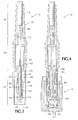
- Figure is a sectional side view of a male element of the connector pair of Figure 1.
- Figure 3 is a sectional side view of a female element of the connector pair of Figure 1.
- Figure 4 is a sectional side view of the connector pair of Figure 1 in a mated condition.
- Figure 1 shows a split or dual banana connector pair 10 having a male portion or plug 12 connected to a lead 14, and a female portion or receptacle 16 for connection to an instrument panel, chassis, or printed circuit board, as will be discussed below.
- the lead connects to a probe (not shown) that contacts a device being tested by the instrument in which the female receptacle is mounted.
- FIG. 2 shows the male plug in greater detail.
- the plug has a plastic insulative housing 20 that has an elongated tubular shape in several sections.
- a shroud section 22 terminates at a free end 24 of the plug.
- the shroud is a thin walled cylinder that protects an elongated conductive plug element 26 coaxially received therein.
- a grip section 28 of the housing has a textured or ribbed outer surface, and a strain relief portion 30 defines perforations to permit flexure, and provides a passage for the lead 14.
- the plug element 26 includes an elongated metal body 32 defining a bore 34.
- a cylindrical portion 36 of the body extends from a flange portion 40 toward the free end 24 of the plug.
- the flange rests against a shoulder in the plug housing bore, and has a butt portion 42 extending partly into the grip section 28.
- a barrel spring 44 is closely received on the cylindrical portion 36, and has elongated spring elements 46 that are positioned against the surface of the cylindrical portion at their ends, and which curve slightly so as to bulge outward at their midsections, in the manner of a conventional barrel spring on a banana plug.
- the plug body bore 34 includes an enlarged end bore portion 50 near the free end.
- the end bore portion receives a plastic sleeve 52 defining a bore smaller than, and coaxial with the body bore 34.
- the sleeve has an enlarged rim 54 that limits insertion of the sleeve into the bore, and which has an outside diameter larger than the end portion of the metal body 32.
- a rigid conductive nail 56 having an enlarged head 60 and an elongated shank 62 is received in the bore 34.
- the shank extends fully through the bore, with a protruding portion 64 extending beyond the end of the butt portion 42 of the body within the grip portion of the housing.
- the head portion of the nail rests against the rim 54 of sleeve 52, and has a diameter approximately equal to the rim diameter, a length less than half its diameter, and quarter-radiused peripheral edges.
- the nail may have an insulative coating on the shaft to prevent electrical contact with the plug body bore near the protruding end.
- the free end of the nail is recessed from the free end 24 of the housing, so that contact by a fingertip is prevented.
- Lead wire 14 has two conductive wires 66, 70.
- Wire 66 is electrically connected to a conductive shroud that fills and rigidly supports the grip section of the flexible plug housing, and which is crimped about the butt portion 42 of the conductive plug body.
- Wire 70 is connected to the protruding end 64 of the nail 56.
- Figure 3 shows the female receptacle portion 16 mounted in a hole 72 of a printed circuit board 74 of an instrument.
- the receptacle is a stout cylindrical body formed of rigid insulative plastic, and having cylindrical exterior surface 76 having several ribs running partially along the length, and terminating at shoulders 80, which are positioned against the board surface.
- the receptacle defines a central bore 82 and an annular bore 84 coaxial with the central bore and extending nearly the full length of the receptacle.
- a cylindrical protrusion having a free end 85 defines bore 82, and is surrounded by bore 84.
- a rigid conductive sleeve contact 86 is closely received by a major portion of the bore, and has a sleeve end 90 positioned against a shoulder in the bore.
- the sleeve defines a sleeve bore 92 having a diameter slightly less than that of an end portion 94 of the receptacle bore. The sleeve extends a substantial depth into the bore, so that a standard male banana connector makes contact when inserted.
- the receptacle bore includes an enlarged chamber 96 at its deepest portion.
- the chamber is enclosed at its base by a cover plate 100 that is absent during installation of the sleeve, then installed and secured to enclose the bore.
- a flexible conductive spring 102 is mounted to the interior surface of the cover 100.
- the spring has a flat base mounted to the cover, and a pair of opposed arms extending upward from the base.
- the spring arms are nearly parallel leaf springs, slanting slightly toward each other. At their free ends, the springs are curved away from each other to facilitate smooth insertion of a plug element between the arms.
- the spring arms are straight until the end flares, and the point of inflection 104 approximately forms the narrowest spacing between the spring arms when at rest.
- Each of the sleeve contact 86 and the spring contact 102 is electrically connected to the board 74 or to other electrical circuitry in the instrument.
- Figure 4 shows the male and female sections of the plugs mated for electrical connection of each of the lead lines to the instrument.
- the free end 85 of the receptacle protrusion rests against the shoulder 40 of the plug body.
- the shroud 22 is received in the annular bore 84.
- the plug body 32 is fully inserted into the central bore, with the widest portions of the barrel spring elements aligned with an intermediate position of the sleeve 86.
- the free ends of the spring arms 102 extend to a distance aligned with the end of the plug body; due to the outward flare of the free ends, contact between the spring and the body is avoided.
- the diameter of the nail head 60 is approximately equal to the length of the spring base, insertion of the head between the spring arm ends to a depth slightly beyond the inflection points 104 spreads apart the arms to a parallel configuration. This further flares spring free ends away from the plug body, and ensures contact with the nail head instead of with the plug sleeve 52.
- the contact with the barrel spring provides a high current capacity main contact, which the contact with the nail head is well suited to a lower current signal or logic line.
- the dimensions of many of the connector elements are compatible with or the same as those of a conventional standard banana plug connector according to military specification A-A-55468; the plug's nail head contact and the associated receptacle spring 102 are departures from the standard connector.
- the cylindrical portion 36 of the plug body 32 has a length of 0.730 inch, a minimum barrel-spring-compressed diameter of 0.160 inch, a maximum diameter about the uncompressed barrel springs of 0.180 inch, with the widest spring point spaced 0.413 inch from the shoulder 40.
- the barrel spring has a length of 0.475 inch, so that it is spaced apart from the shoulder by 0.170 inch.
- the cylindrical portion 36 of the plug body extends only to 0.645 inch from the shoulder, with the sleeve rim adding another 0.040 inch, and the nail head adding a final 0.045 inch.
- the nail head has a diameter of 0.150 inch, and the sleeve rim has a flange diameter of 0.145 inch.
- the sleeve 86 has a length of 0.410 inch, and is spaced apart from the free end 85 of the receptacle by 0.160 inch.
- the sleeve has an inside diameter of 0.160 inch.
- either portion of the disclosed connector may be used as or in conjunction with a standard single plug banana plug or receptacle.
- the second nail head/receptacle spring contacts may be idle while the primary barrel spring/sleeve contact is used.
- a single receptacle on an instrument panel may serve as a two line or split connection, as might be used for a thermocouple or shielded signal lead, while also serving as a receptacle for a conventional banana lead for other purposes. This versatility reduces the number of receptacles required for a given number of dual and single connections.
Applications Claiming Priority (2)
| Application Number | Priority Date | Filing Date | Title |
|---|---|---|---|
| US988500 | 1997-12-10 | ||
| US08/988,500 US5915995A (en) | 1997-12-10 | 1997-12-10 | Dual contact banana connector |
Publications (2)
| Publication Number | Publication Date |
|---|---|
| EP0923170A2 true EP0923170A2 (fr) | 1999-06-16 |
| EP0923170A3 EP0923170A3 (fr) | 2000-08-23 |
Family
ID=25534182
Family Applications (1)
| Application Number | Title | Priority Date | Filing Date |
|---|---|---|---|
| EP98309413A Withdrawn EP0923170A3 (fr) | 1997-12-10 | 1998-11-17 | Fiche banane avec contact double |
Country Status (3)
| Country | Link |
|---|---|
| US (1) | US5915995A (fr) |
| EP (1) | EP0923170A3 (fr) |
| TW (1) | TW441150B (fr) |
Cited By (6)
| Publication number | Priority date | Publication date | Assignee | Title |
|---|---|---|---|---|
| EP1115177A2 (fr) * | 2000-01-07 | 2001-07-11 | J. D'Addario & Company, Inc. | Connecteur électrique à fiche |
| EP1182739A2 (fr) * | 2000-08-24 | 2002-02-27 | Harting Automotive GmbH & Co. KG | Contact à haute intensité |
| EP1517410A1 (fr) * | 2002-06-26 | 2005-03-23 | Hongbin Zhang | Fiche banane |
| GB2447648A (en) * | 2007-03-16 | 2008-09-24 | Cliff Electronic Components Ltd | Connector adapting for different sized pins |
| CH697606B1 (de) * | 2005-08-26 | 2008-12-15 | Multi Holding Ag | Steckbare Kabelkupplung. |
| EP2780985B1 (fr) * | 2011-11-18 | 2016-12-14 | Rosenberger Hochfrequenztechnik GmbH & Co. KG | Elément de liaison |
Families Citing this family (11)
| Publication number | Priority date | Publication date | Assignee | Title |
|---|---|---|---|---|
| US6945803B2 (en) * | 1997-06-27 | 2005-09-20 | Patrick Potega | Positionable-connect apparatus for electrically coupling selected electrical devices |
| US6019260A (en) * | 1997-08-08 | 2000-02-01 | Spotless Plastics Pty. Ltd. | Side indicator hangers and method and apparatus for removing indicators from hangers |
| US6981895B2 (en) * | 1999-08-23 | 2006-01-03 | Patrick Potega | Interface apparatus for selectively connecting electrical devices |
| US6869316B2 (en) * | 2002-06-27 | 2005-03-22 | Dell Products L.P. | Three contact barrel power connector assembly |
| JP4971857B2 (ja) * | 2007-03-29 | 2012-07-11 | 富士通コンポーネント株式会社 | コネクタ装置 |
| US7462068B2 (en) * | 2007-04-03 | 2008-12-09 | John Mezzalingua Associates, Inc. | Sure-grip RCA-type connector and method of use thereof |
| CH705431B1 (it) * | 2008-03-07 | 2013-03-15 | Claudio Soresina | Dispostivo girevole per il collegamento elettrico di elettrodomestici o elettroutensili. |
| US7934943B2 (en) * | 2008-10-31 | 2011-05-03 | Tyco Electronics Corporation | Strain relief boot for a connector and cable assembly |
| US9761993B2 (en) * | 2015-01-08 | 2017-09-12 | Westek Electronics, Inc. | Banana plug |
| US10986431B2 (en) | 2017-10-07 | 2021-04-20 | Point Source Audio, Inc. | Wearable microphone housing with built-in redundancy |
| USD916030S1 (en) * | 2018-06-27 | 2021-04-13 | Point Source Audio, Inc. | Audio connector |
Citations (5)
| Publication number | Priority date | Publication date | Assignee | Title |
|---|---|---|---|---|
| US4325599A (en) * | 1979-12-05 | 1982-04-20 | Amp Incorporated | Phone plug |
| US4988315A (en) * | 1990-02-21 | 1991-01-29 | Safco Corporation | Electrical adapter plug |
| US5022872A (en) * | 1989-07-12 | 1991-06-11 | Hosiden Electronics Co., Ltd. | Jack |
| US5147221A (en) * | 1989-08-13 | 1992-09-15 | The Starling Manufacturing Company | Combination socket and wingless cable-end radio pin connector |
| US5230641A (en) * | 1992-08-06 | 1993-07-27 | Safco Corporation | Electrical receptacle |
Family Cites Families (3)
| Publication number | Priority date | Publication date | Assignee | Title |
|---|---|---|---|---|
| SU1510031A1 (ru) * | 1987-06-19 | 1989-09-23 | Томский научно-исследовательский, проектно-конструкторский и технологический кабельный институт | Штепсельна розетка |
| FR2682820A1 (fr) * | 1991-10-16 | 1993-04-23 | Michelin & Cie | Connecteur electrique et ses composants. |
| JP2955498B2 (ja) * | 1995-09-11 | 1999-10-04 | 英朗 茂治 | カープラグ |
-
1997
- 1997-12-10 US US08/988,500 patent/US5915995A/en not_active Expired - Fee Related
-
1998
- 1998-11-16 TW TW087118924A patent/TW441150B/zh active
- 1998-11-17 EP EP98309413A patent/EP0923170A3/fr not_active Withdrawn
Patent Citations (5)
| Publication number | Priority date | Publication date | Assignee | Title |
|---|---|---|---|---|
| US4325599A (en) * | 1979-12-05 | 1982-04-20 | Amp Incorporated | Phone plug |
| US5022872A (en) * | 1989-07-12 | 1991-06-11 | Hosiden Electronics Co., Ltd. | Jack |
| US5147221A (en) * | 1989-08-13 | 1992-09-15 | The Starling Manufacturing Company | Combination socket and wingless cable-end radio pin connector |
| US4988315A (en) * | 1990-02-21 | 1991-01-29 | Safco Corporation | Electrical adapter plug |
| US5230641A (en) * | 1992-08-06 | 1993-07-27 | Safco Corporation | Electrical receptacle |
Cited By (15)
| Publication number | Priority date | Publication date | Assignee | Title |
|---|---|---|---|---|
| EP1115177A2 (fr) * | 2000-01-07 | 2001-07-11 | J. D'Addario & Company, Inc. | Connecteur électrique à fiche |
| US6729912B2 (en) | 2000-01-07 | 2004-05-04 | J. D'addario & Company, Inc. | Audio signal connector |
| EP1115177A3 (fr) * | 2000-01-07 | 2002-03-06 | J. D'Addario & Company, Inc. | Connecteur électrique à fiche |
| US6494746B2 (en) | 2000-01-07 | 2002-12-17 | J. D'addario & Company, Inc. | Electronic signal plug connector |
| US6533617B1 (en) | 2000-01-07 | 2003-03-18 | J. D'addario & Company, Inc. | Electrical plug connectors |
| US6568964B2 (en) | 2000-01-07 | 2003-05-27 | J. D'addario & Company, Inc. | RCA-type electrical plug connector |
| EP1182739A3 (fr) * | 2000-08-24 | 2003-06-04 | Harting Automotive GmbH & Co. KG | Contact à haute intensité |
| EP1182739A2 (fr) * | 2000-08-24 | 2002-02-27 | Harting Automotive GmbH & Co. KG | Contact à haute intensité |
| EP1517410A1 (fr) * | 2002-06-26 | 2005-03-23 | Hongbin Zhang | Fiche banane |
| EP1517410A4 (fr) * | 2002-06-26 | 2006-12-20 | Hongbin Zhang | Fiche banane |
| CH697606B1 (de) * | 2005-08-26 | 2008-12-15 | Multi Holding Ag | Steckbare Kabelkupplung. |
| GB2447648A (en) * | 2007-03-16 | 2008-09-24 | Cliff Electronic Components Ltd | Connector adapting for different sized pins |
| US7648380B2 (en) | 2007-03-16 | 2010-01-19 | Cliff Electronic Components Limited | DC plug connector |
| GB2447648B (en) * | 2007-03-16 | 2011-06-01 | Cliff Electronic Components Ltd | An improved DC plug connector |
| EP2780985B1 (fr) * | 2011-11-18 | 2016-12-14 | Rosenberger Hochfrequenztechnik GmbH & Co. KG | Elément de liaison |
Also Published As
| Publication number | Publication date |
|---|---|
| TW441150B (en) | 2001-06-16 |
| EP0923170A3 (fr) | 2000-08-23 |
| US5915995A (en) | 1999-06-29 |
Similar Documents
| Publication | Publication Date | Title |
|---|---|---|
| US5915995A (en) | Dual contact banana connector | |
| US5362251A (en) | Solderless coaxial connector plug | |
| EP1032087B1 (fr) | Connecteur male et femelle, et ensemble connecteur | |
| US6517379B2 (en) | Plug connector | |
| US4647135A (en) | Plug for audio device | |
| US4655534A (en) | Right angle coaxial connector | |
| US6676443B1 (en) | All metal shell BNC electrical connector | |
| US6808395B2 (en) | Coaxial cable termination connector for connecting to a printed circuit board | |
| US6036540A (en) | Coaxial connector with ring contact having cantilevered fingers | |
| US6126465A (en) | Electrical connector system having dual purpose jack | |
| US7341459B1 (en) | Multi-signal single pin connector | |
| US5389012A (en) | Coaxial conductor and a coax connector thereof | |
| US20090318019A1 (en) | Electrical connector for terminating a coaxial cable | |
| CA2140308A1 (fr) | Connecteur a rotation muni d'une borne pour cable coaxial | |
| US11901678B2 (en) | Contact member for electrical connector | |
| US6390840B1 (en) | Auto termination PCB mount connector | |
| US6753475B2 (en) | Shielding terminal for coaxial cable | |
| US5860833A (en) | Electrical connector having a probe positionable between a pair of spaced positions | |
| US4398783A (en) | Coaxial cable connector | |
| US8215985B2 (en) | Step up pin for coax cable connector | |
| US6896549B2 (en) | Device for connecting coaxial conductors to a plug-in connector | |
| US9748710B2 (en) | RF connector with push-on connection | |
| CN210326253U (zh) | 插针端子 | |
| US7645163B2 (en) | Step up pin for coax cable connector | |
| EP1261076A3 (fr) | Connecteur électrique imperméable |
Legal Events
| Date | Code | Title | Description |
|---|---|---|---|
| PUAI | Public reference made under article 153(3) epc to a published international application that has entered the european phase |
Free format text: ORIGINAL CODE: 0009012 |
|
| AK | Designated contracting states |
Kind code of ref document: A2 Designated state(s): DE FR |
|
| AX | Request for extension of the european patent |
Free format text: AL;LT;LV;MK;RO;SI |
|
| PUAL | Search report despatched |
Free format text: ORIGINAL CODE: 0009013 |
|
| AK | Designated contracting states |
Kind code of ref document: A3 Designated state(s): AT BE CH CY DE DK ES FI FR GB GR IE IT LI LU MC NL PT SE |
|
| AX | Request for extension of the european patent |
Free format text: AL;LT;LV;MK;RO;SI |
|
| RIC1 | Information provided on ipc code assigned before grant |
Free format text: 7H 01R 15/00 A, 7H 01R 13/05 B, 7H 01R 17/18 B |
|
| 17P | Request for examination filed |
Effective date: 20010129 |
|
| AKX | Designation fees paid |
Free format text: DE FR |
|
| 17Q | First examination report despatched |
Effective date: 20020322 |
|
| STAA | Information on the status of an ep patent application or granted ep patent |
Free format text: STATUS: THE APPLICATION IS DEEMED TO BE WITHDRAWN |
|
| 18D | Application deemed to be withdrawn |
Effective date: 20020802 |