EP0922851B1 - LPG reservoir for an internal combustion engine adapted to be operated selectively with gasoline and LPG - Google Patents
LPG reservoir for an internal combustion engine adapted to be operated selectively with gasoline and LPG Download PDFInfo
- Publication number
- EP0922851B1 EP0922851B1 EP98830734A EP98830734A EP0922851B1 EP 0922851 B1 EP0922851 B1 EP 0922851B1 EP 98830734 A EP98830734 A EP 98830734A EP 98830734 A EP98830734 A EP 98830734A EP 0922851 B1 EP0922851 B1 EP 0922851B1
- Authority
- EP
- European Patent Office
- Prior art keywords
- lpg
- reservoir
- gasoline
- connecting element
- conduit
- Prior art date
- Legal status (The legal status is an assumption and is not a legal conclusion. Google has not performed a legal analysis and makes no representation as to the accuracy of the status listed.)
- Expired - Lifetime
Links
Images

Classifications
-
- F—MECHANICAL ENGINEERING; LIGHTING; HEATING; WEAPONS; BLASTING
- F02—COMBUSTION ENGINES; HOT-GAS OR COMBUSTION-PRODUCT ENGINE PLANTS
- F02M—SUPPLYING COMBUSTION ENGINES IN GENERAL WITH COMBUSTIBLE MIXTURES OR CONSTITUENTS THEREOF
- F02M21/00—Apparatus for supplying engines with non-liquid fuels, e.g. gaseous fuels stored in liquid form
- F02M21/02—Apparatus for supplying engines with non-liquid fuels, e.g. gaseous fuels stored in liquid form for gaseous fuels
- F02M21/0218—Details on the gaseous fuel supply system, e.g. tanks, valves, pipes, pumps, rails, injectors or mixers
- F02M21/0248—Injectors
-
- F—MECHANICAL ENGINEERING; LIGHTING; HEATING; WEAPONS; BLASTING
- F02—COMBUSTION ENGINES; HOT-GAS OR COMBUSTION-PRODUCT ENGINE PLANTS
- F02D—CONTROLLING COMBUSTION ENGINES
- F02D19/00—Controlling engines characterised by their use of non-liquid fuels, pluralities of fuels, or non-fuel substances added to the combustible mixtures
- F02D19/02—Controlling engines characterised by their use of non-liquid fuels, pluralities of fuels, or non-fuel substances added to the combustible mixtures peculiar to engines working with gaseous fuels
- F02D19/026—Measuring or estimating parameters related to the fuel supply system
- F02D19/027—Determining the fuel pressure, temperature or volume flow, the fuel tank fill level or a valve position
-
- F—MECHANICAL ENGINEERING; LIGHTING; HEATING; WEAPONS; BLASTING
- F02—COMBUSTION ENGINES; HOT-GAS OR COMBUSTION-PRODUCT ENGINE PLANTS
- F02D—CONTROLLING COMBUSTION ENGINES
- F02D19/00—Controlling engines characterised by their use of non-liquid fuels, pluralities of fuels, or non-fuel substances added to the combustible mixtures
- F02D19/06—Controlling engines characterised by their use of non-liquid fuels, pluralities of fuels, or non-fuel substances added to the combustible mixtures peculiar to engines working with pluralities of fuels, e.g. alternatively with light and heavy fuel oil, other than engines indifferent to the fuel consumed
- F02D19/0602—Control of components of the fuel supply system
- F02D19/0613—Switch-over from one fuel to another
- F02D19/0615—Switch-over from one fuel to another being initiated by automatic means, e.g. based on engine or vehicle operating conditions
-
- F—MECHANICAL ENGINEERING; LIGHTING; HEATING; WEAPONS; BLASTING
- F02—COMBUSTION ENGINES; HOT-GAS OR COMBUSTION-PRODUCT ENGINE PLANTS
- F02D—CONTROLLING COMBUSTION ENGINES
- F02D19/00—Controlling engines characterised by their use of non-liquid fuels, pluralities of fuels, or non-fuel substances added to the combustible mixtures
- F02D19/06—Controlling engines characterised by their use of non-liquid fuels, pluralities of fuels, or non-fuel substances added to the combustible mixtures peculiar to engines working with pluralities of fuels, e.g. alternatively with light and heavy fuel oil, other than engines indifferent to the fuel consumed
- F02D19/0639—Controlling engines characterised by their use of non-liquid fuels, pluralities of fuels, or non-fuel substances added to the combustible mixtures peculiar to engines working with pluralities of fuels, e.g. alternatively with light and heavy fuel oil, other than engines indifferent to the fuel consumed characterised by the type of fuels
- F02D19/0642—Controlling engines characterised by their use of non-liquid fuels, pluralities of fuels, or non-fuel substances added to the combustible mixtures peculiar to engines working with pluralities of fuels, e.g. alternatively with light and heavy fuel oil, other than engines indifferent to the fuel consumed characterised by the type of fuels at least one fuel being gaseous, the other fuels being gaseous or liquid at standard conditions
- F02D19/0647—Controlling engines characterised by their use of non-liquid fuels, pluralities of fuels, or non-fuel substances added to the combustible mixtures peculiar to engines working with pluralities of fuels, e.g. alternatively with light and heavy fuel oil, other than engines indifferent to the fuel consumed characterised by the type of fuels at least one fuel being gaseous, the other fuels being gaseous or liquid at standard conditions the gaseous fuel being liquefied petroleum gas [LPG], liquefied natural gas [LNG], compressed natural gas [CNG] or dimethyl ether [DME]
-
- F—MECHANICAL ENGINEERING; LIGHTING; HEATING; WEAPONS; BLASTING
- F02—COMBUSTION ENGINES; HOT-GAS OR COMBUSTION-PRODUCT ENGINE PLANTS
- F02M—SUPPLYING COMBUSTION ENGINES IN GENERAL WITH COMBUSTIBLE MIXTURES OR CONSTITUENTS THEREOF
- F02M21/00—Apparatus for supplying engines with non-liquid fuels, e.g. gaseous fuels stored in liquid form
- F02M21/02—Apparatus for supplying engines with non-liquid fuels, e.g. gaseous fuels stored in liquid form for gaseous fuels
- F02M21/0218—Details on the gaseous fuel supply system, e.g. tanks, valves, pipes, pumps, rails, injectors or mixers
- F02M21/0221—Fuel storage reservoirs, e.g. cryogenic tanks
-
- F—MECHANICAL ENGINEERING; LIGHTING; HEATING; WEAPONS; BLASTING
- F02—COMBUSTION ENGINES; HOT-GAS OR COMBUSTION-PRODUCT ENGINE PLANTS
- F02M—SUPPLYING COMBUSTION ENGINES IN GENERAL WITH COMBUSTIBLE MIXTURES OR CONSTITUENTS THEREOF
- F02M21/00—Apparatus for supplying engines with non-liquid fuels, e.g. gaseous fuels stored in liquid form
- F02M21/02—Apparatus for supplying engines with non-liquid fuels, e.g. gaseous fuels stored in liquid form for gaseous fuels
- F02M21/0218—Details on the gaseous fuel supply system, e.g. tanks, valves, pipes, pumps, rails, injectors or mixers
- F02M21/0245—High pressure fuel supply systems; Rails; Pumps; Arrangement of valves
-
- F—MECHANICAL ENGINEERING; LIGHTING; HEATING; WEAPONS; BLASTING
- F02—COMBUSTION ENGINES; HOT-GAS OR COMBUSTION-PRODUCT ENGINE PLANTS
- F02M—SUPPLYING COMBUSTION ENGINES IN GENERAL WITH COMBUSTIBLE MIXTURES OR CONSTITUENTS THEREOF
- F02M37/00—Apparatus or systems for feeding liquid fuel from storage containers to carburettors or fuel-injection apparatus; Arrangements for purifying liquid fuel specially adapted for, or arranged on, internal-combustion engines
- F02M37/04—Feeding by means of driven pumps
- F02M37/08—Feeding by means of driven pumps electrically driven
- F02M37/10—Feeding by means of driven pumps electrically driven submerged in fuel, e.g. in reservoir
-
- F—MECHANICAL ENGINEERING; LIGHTING; HEATING; WEAPONS; BLASTING
- F02—COMBUSTION ENGINES; HOT-GAS OR COMBUSTION-PRODUCT ENGINE PLANTS
- F02D—CONTROLLING COMBUSTION ENGINES
- F02D19/00—Controlling engines characterised by their use of non-liquid fuels, pluralities of fuels, or non-fuel substances added to the combustible mixtures
- F02D19/06—Controlling engines characterised by their use of non-liquid fuels, pluralities of fuels, or non-fuel substances added to the combustible mixtures peculiar to engines working with pluralities of fuels, e.g. alternatively with light and heavy fuel oil, other than engines indifferent to the fuel consumed
- F02D19/0663—Details on the fuel supply system, e.g. tanks, valves, pipes, pumps, rails, injectors or mixers
- F02D19/0686—Injectors
- F02D19/0692—Arrangement of multiple injectors per combustion chamber
-
- Y—GENERAL TAGGING OF NEW TECHNOLOGICAL DEVELOPMENTS; GENERAL TAGGING OF CROSS-SECTIONAL TECHNOLOGIES SPANNING OVER SEVERAL SECTIONS OF THE IPC; TECHNICAL SUBJECTS COVERED BY FORMER USPC CROSS-REFERENCE ART COLLECTIONS [XRACs] AND DIGESTS
- Y02—TECHNOLOGIES OR APPLICATIONS FOR MITIGATION OR ADAPTATION AGAINST CLIMATE CHANGE
- Y02T—CLIMATE CHANGE MITIGATION TECHNOLOGIES RELATED TO TRANSPORTATION
- Y02T10/00—Road transport of goods or passengers
- Y02T10/10—Internal combustion engine [ICE] based vehicles
- Y02T10/30—Use of alternative fuels, e.g. biofuels
Definitions
- the present invention relates to a LPG reservoir which is for use in a fuel feeding system for an internal combustion engine adapted to be operated selectively with gasoline and LPG.
- Fuel feeding systems of this type are known (see European patent EP-B-0 725 205 of the same Applicant and the corresponding US patent No. 5,592,924), which comprise:
- So-called "bi-fuel"-type feeding systems are also known, i.e. systems adapted to be operated either with gasoline or with LPG, in which an automatic switch from the LPG mode to the gasoline mode is caused when the LPG level in the reservoir decreases below a minimum admissible value.
- a device as set forth in the pre-characterizing portion of claim 1 is known from EP-A-0 718 484.
- the object of the present invention is that of providing a LPG reservoir which is to be used in a system of the above indicated type which has a relatively simple and efficient structure.
- the invention provides a reservoir having the features indicated in claim 1.
- said outlet connecting element, said return connecting element and said cable guiding sleeve are all carried by a single plate connected to the reservoir wall.
- the reservoir according to the invention has a relatively simple structure, and yet is extremely efficient, is adapted to be assembled with relatively simple and rapid operations and is able to operate in the best way in a fuel feeding system of the above described type.
- the pump unit forming part of the reservoir includes both the outlet conduit, and the return conduit and the level sensing device which is to be used both to enable the user to control the LPG level in the reservoir and to enable the system to automatically cause switching from the LPG mode to the gasoline mode when the LPG level in the reservoir decreases below the minimum admissible value for proper operation of the pump.
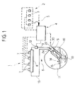
- reference numeral 1 generally designates a feeding system for an internal combustion engine of a motor-vehicle, adapted to operate selectively with gasoline and LPG.
- the system 1 includes a subsystem 2 for feeding gasoline to the engine, including a plurality of gasoline injectors 3 associated with the various cylinders of the engine and controlled by an electronic control unit 4 on the basis of signals 5 sent to unit 4 and indicative of various parameters of operation of the engine.
- the subsystem 2 can be provided as a conventional electronically controlled gasoline injection system and therefore is not illustrated in detail in the present description and in the annexed drawings.
- the feeding system 1 further includes a subsystem 6 for feeding LPG to the engine.
- Systems of this type have been known and used and have also formed the subject of previous patents of the same Applicant (see for example European patent EP-B-0 725 208 and the corresponding US patent No. 5,592,924).
- the subsystem 6 comprises a plurality of LPG injectors 7 which are associated with the various cylinders of the engine and communicate with a feeding manifold or rail 8.
- the rail 8 is connected through a conduit 9 to the outlet of a pump 10, arranged inside a LPG reservoir 11.
- a pressure sensor 12 is arranged in conduit 9.
- the LPG fed in excess to the injectors 7 returns to the reservoir 11 through a return conduit 13 which communicates with reservoir 11 by means of a one-way valve (not shown in the drawing) which prevents a LPG flow through conduit 13 towards rail 8.
- a level sensor 14 comprising a float 15 and a transducer 16.
- Sensor 12 and transducer 16 send signals indicative of the conduit pressure 9 and LPG level within reservoir 11 to the electronic control unit 4.
- the electronic control unit 4 is provided for controlling also switching between the gasoline operation mode and the LPG operation mode. During the LPG operation mode, the same electronic control unit 4 attends to controlling the LPG injectors 7 on the basis of the signal received from sensor 12 which detects the LPG pressure (which is a function of the temperature), so as to enable the opening time of the injectors 7 to be controlled accordingly.
- the pump 10 forms part of a pump unit 17, including a canister 18 having a cylindrical shape and surrounding pump 10.
- the canister 18 has been illustrated in cross-section in figure 2 for an easier representation of pump 10.
- Pump 10 has an intake mouth 19 at its bottom, adjacent to the reservoir bottom and an outlet conduit 20 at its top.
- Conduit 20 opens above canister 18 and is connected by means of a conduit 21 arranged inside the reservoir to an outlet connecting element 22 which is arranged through the wall of reservoir 11 and is carried by a plate 23.
- the outlet connecting element 22 is connected to conduit 9 which feeds LPG to rail 8 (figure 1).
- the same plate 23 also carries a return connecting element 24 for connecting the return conduit 13.
- the return connecting element 24 also includes a one-way valve, which prevents a LPG flow from reservoir 11 to rail 8 through conduit 13, similarly to what has been proposed in previous Italian patent application TO96A000983 and in parallel European patent application No. 97830620.7 of the same Applicant, which were still secret at the priority date of the present application. Due to the use of this one-way valve, it is not necessary to provide a pressure regulating device in conduit 13 as shown instead in other previous patents of the Applicant which have been mentioned above (EP-B-0 725 205 and US-A-5 592 924).
- the return connecting element 24 is connected to a conduit 25 arranged inside reservoir 11 which ends in a connecting element 26 carried by the upper end of canister 18.
- This upper end of canister 18 also carries a connecting element 27 for connecting the outlet conduit 20 of the pump with conduit 21 connected to the outlet connecting element 22.
- the upper end of canister 18 of the pump unit 17 also supports the transducer 16 of the level sensor device 14.
- This transducer is mechanically connected to a rocking lever 25 whose radially outer end has the float 15.
- the transducer 16 includes an outlet electric wire 29 which is connected to the outside of the reservoir through a cable guiding sleeve 30 which is also carried by plate 23 on which the two connecting elements 22, 24 are mounted.
- the reservoir according to the invention has a simple and at the same time efficient structure, which is adapted to be assembled with easy and rapid operations, due to that the pump unit 17 includes also the level sensor device and the connecting elements 26, 27 for the two inner conduits 25, 21, as well as due to that a single plate 23 at the outside of the reservoir carries both the outlet connecting element 22, and the return connecting element 24 and the cable guiding sleeve 30 for connecting the outlet electric wire 29 to the level sensor.
- the reservoir according to the invention is adapted to be used in a particularly advantageous way in a fuel feeding system in which the electronic control means automatically attend to switching the system from the gasoline mode to the LPG mode when the LPG level in the reservoir 11 lowers below a minimum value for proper operation of the pump 17.
Landscapes
- Engineering & Computer Science (AREA)
- Chemical & Material Sciences (AREA)
- Combustion & Propulsion (AREA)
- Mechanical Engineering (AREA)
- General Engineering & Computer Science (AREA)
- Oil, Petroleum & Natural Gas (AREA)
- Chemical Kinetics & Catalysis (AREA)
- General Chemical & Material Sciences (AREA)
- Output Control And Ontrol Of Special Type Engine (AREA)
- Electrical Control Of Air Or Fuel Supplied To Internal-Combustion Engine (AREA)
- Filling Or Discharging Of Gas Storage Vessels (AREA)
- Supplying Secondary Fuel Or The Like To Fuel, Air Or Fuel-Air Mixtures (AREA)
Description
- gasoline feeding means including a plurality of injectors associated with the engine cylinders,
- electronic control means for controlling the gasoline injectors, adapted to receiving signals indicative of various parameters of operation of the engine as well as to controlling the gasoline injectors accordingly, and
- LPG feeding means, including:
- a plurality of LPG injectors associated with the engine cylinders,
- a LPG feeding manifold or rail for feeding LPG to said injectors,
- a LPG feeding conduit for feeding LPG from the reservoir to said rail,
- a return conduit for returning the LPG fed in excess to the injectors to the reservoir,
- sensor means for sensing the LPG level in the reservoir,
- a pump interposed in the LPG feeding conduit for feeding LPG from the reservoir to the rail,
- said electronic control means being adapted to controlling switching between the gasoline operation mode and the LPG operation mode and being further adapted to controlling the LPG injectors in the LPG operation mode.
Claims (3)
- LPG reservoir, which is for use in a fuel feeding system for an internal combustion engine adapted to be operated selectively with gasoline and LPG, said system comprising:wherein said reservoir includes:gasoline feeding means (2), including a plurality of injectors (3) associated with the engine cylinders, andelectronic control means (4) for controlling the gasoline injectors (3), adapted to receiving signals (5) indicative of various parameters of operation of the engine as well as to controlling the gasoline injectors (3) accordingly, andLPG feeding means, including:a plurality of LPG injectors (7) associated with the engine cylinders,a LPG feeding manifold or rail (8) for feeding LPG to said injectors (7),a LPG reservoir (11),a conduit (9) for feeding LPG from the reservoir (11) to said rail (8),a return conduit (13) for returning the LPG fed in excess to the injectors (7) into the reservoir (11),sensor means (14) for sensing the LPG level in the reservoir (11),said electronic control means being adapted to controlling switching between the gasoline operation mode and the LPG operation mode and being further adapted to controlling the LPG injectors,said electronic control means being further adapted to automatically switching the system from the LPG mode to the gasoline mode when said sensor means detect a level of LPG in the reservoir (11) below admissible value,characterized in that said float (15) and said transducer (16) are both supported by the pump unit (17) and said transducer (16) having an associated outlet electric wire (29) connected at the outside through a cable guiding sleeve (30) which is arranged through the wall of the reservoir (11), and in that said pump unit includes a canister (18) surrounding the pump (10), whose structure supports a connecting element (27) for connecting the outlet conduit (20) of the pump to a conduit (21) inside the reservoir which is on its turn connected to said outlet connecting element (22); a connecting element (26) communicating with the inner chamber of the canister (18), which is connected to an inner conduit (25) of the reservoir (11) opening in said return connecting element (24); the structure (18) of the canister further supporting said transducer (16) and the structure of the float (15).a pump unit (17), including said pump (10), arranged within the reservoir (11), having an intake mouth (19) and an outlet conduit (20) connected to an outlet connecting element (2) opening at the outside of the reservoir (11),a return connecting element (24), also opening at the outside of the reservoir (11), for connecting said return conduit (13) to the inner chamber of the reservoir (11), andsaid level sensor (14), including a transducer (16) mechanically connected to a float (15) and adapted to send an electric signal indicative of the position of the float (15),
- Reservoir according to claim 1, characterized in that said outlet connecting element (22), said return connecting element (24) and said cable guiding sleeve (30) are all carried by a single plate (23) connected to the wall of the reservoir (11).
- System for feeding an internal combustion engine adapted to selectively operate with LPG and gasoline, characterized in that it includes a reservoir according to any of the previous claims.
Applications Claiming Priority (2)
| Application Number | Priority Date | Filing Date | Title |
|---|---|---|---|
| ITTO971084 | 1997-12-12 | ||
| IT97TO001084A IT1296634B1 (en) | 1997-12-12 | 1997-12-12 | LPG TANK FOR AN INTERNAL COMBUSTION ENGINE SUITABLE TO OPERATE SELECTIVELY WITH PETROL AND LPG |
Publications (3)
| Publication Number | Publication Date |
|---|---|
| EP0922851A2 EP0922851A2 (en) | 1999-06-16 |
| EP0922851A3 EP0922851A3 (en) | 2000-05-03 |
| EP0922851B1 true EP0922851B1 (en) | 2002-01-09 |
Family
ID=11416194
Family Applications (1)
| Application Number | Title | Priority Date | Filing Date |
|---|---|---|---|
| EP98830734A Expired - Lifetime EP0922851B1 (en) | 1997-12-12 | 1998-12-04 | LPG reservoir for an internal combustion engine adapted to be operated selectively with gasoline and LPG |
Country Status (6)
| Country | Link |
|---|---|
| US (1) | US6050237A (en) |
| EP (1) | EP0922851B1 (en) |
| AU (1) | AU733900B2 (en) |
| DE (1) | DE69803433T2 (en) |
| ES (1) | ES2170469T3 (en) |
| IT (1) | IT1296634B1 (en) |
Cited By (1)
| Publication number | Priority date | Publication date | Assignee | Title |
|---|---|---|---|---|
| EP1249596A2 (en) | 2001-04-13 | 2002-10-16 | C.R.F. Società Consortile per Azioni | Tank for a LPG injection system for internal combustion engines |
Families Citing this family (16)
| Publication number | Priority date | Publication date | Assignee | Title |
|---|---|---|---|---|
| IT1308747B1 (en) * | 1999-06-22 | 2002-01-10 | Fiat Ricerche | CHECK PROCEDURE FOR THE FUEL SWITCHING PHASE IN AN INTERNAL COMBUSTION ENGINE SUITABLE TO OPERATE SELECTIVELY WITH |
| AU779307B2 (en) * | 2001-04-13 | 2005-01-13 | C.R.F. Societa Consortile Per Azioni | Tank for a system for injection supply of LPG for internal-combustion engines |
| US6543423B2 (en) | 2001-07-23 | 2003-04-08 | Ford Global Technologies, Inc. | Control system and method for a bi-fuel engine |
| AT412581B (en) | 2001-08-30 | 2005-04-25 | Vogel & Noot Waermetechnik Ag | PANEL FOR PLATE HEATING (COOL) BODY AND METHOD FOR PRODUCING THE PANEL |
| ITTO20021136A1 (en) * | 2002-12-31 | 2004-07-01 | Fiat Ricerche | INJECTION FUEL SYSTEM AND PROCEDURE |
| ITTO20030097A1 (en) * | 2003-02-11 | 2004-08-12 | Fiat Ricerche | LEVEL SENSOR DEVICE FOR A TANK OF |
| ITTO20030230A1 (en) | 2003-03-27 | 2004-09-28 | Fiat Ricerche | CONNECTOR ORGAN FOR ELECTRICAL CONNECTIONS THROUGH |
| KR100852600B1 (en) | 2005-12-19 | 2008-08-14 | 콘티넨탈 오토모티브 시스템 주식회사 | Engine driving device and method for gasoline and Elpgi combined vehicles |
| JP5605220B2 (en) * | 2007-05-23 | 2014-10-15 | インターロッキング ビルディングス ピーティーワイ リミテッド | Manufacturing and installation method of high pressure liquid LPG fuel supply device and dual or mixed fuel supply system |
| WO2010017442A1 (en) * | 2008-08-08 | 2010-02-11 | Mavinahally Nagesh Siddabasapp | Integrally cast block and upper crankcase |
| NL2002792C2 (en) * | 2009-04-24 | 2010-10-28 | Vialle Alternative Fuel Systems Bv | STOCK COVER AND LPG FUEL STOCK. |
| GB0915124D0 (en) * | 2009-09-01 | 2009-10-07 | Hillriver Ltd | Fuel level sensing device |
| US8714130B2 (en) * | 2009-10-19 | 2014-05-06 | Nagesh S. Mavinahally | Integrally cast block and upper crankcase |
| US9567918B2 (en) | 2010-05-10 | 2017-02-14 | Go Natural Cng, Llc | Bi-fuel control systems for automotive vehicles and related methods |
| US11567907B2 (en) | 2013-03-14 | 2023-01-31 | Workshare, Ltd. | Method and system for comparing document versions encoded in a hierarchical representation |
| DE102016215972A1 (en) | 2016-08-25 | 2018-03-01 | Ford Global Technologies, Llc | A fuel supply system, internal combustion engine and method for supplying an internal combustion engine with an LPG fuel |
Family Cites Families (14)
| Publication number | Priority date | Publication date | Assignee | Title |
|---|---|---|---|---|
| US3794000A (en) * | 1971-09-17 | 1974-02-26 | Ethyl Corp | Fuel system for separating volatile fuel from gasoline |
| US3783849A (en) * | 1971-11-05 | 1974-01-08 | Ethyl Corp | Dual fuel system |
| JPS5677634U (en) * | 1979-11-22 | 1981-06-24 | ||
| GB2222437B (en) * | 1988-09-03 | 1990-11-14 | Delco Electronic Overseas Corp | Aspirator assembly |
| US4972875A (en) * | 1989-12-26 | 1990-11-27 | General Motors Corporation | High pressure hose for modular fuel delivery system |
| NL9301635A (en) * | 1993-09-21 | 1995-04-18 | Gentec Bv | Fuel supply metering system, method and electronic control unit of a multi-fuel combustion device. |
| DE59505907D1 (en) * | 1994-12-22 | 1999-06-17 | Siemens Ag | Arrangement for operating an internal combustion engine with different fuels |
| JPH08210083A (en) | 1995-02-02 | 1996-08-13 | Houshiyou:Kk | Cutoff method and device for pit mouth in underground piping work |
| ES2105917T3 (en) | 1995-02-03 | 1997-10-16 | Fiat Ricerche | INTERNAL COMBUSTION ENGINE ADAPTED TO OPERATE SELECTIVELY WITH GASOLINE INJECTION OR WITH LPG. |
| US5623907A (en) * | 1995-06-09 | 1997-04-29 | Walbro Corporation | Liquid propane fuel delivery system |
| IT235665Y1 (en) * | 1995-07-14 | 2000-07-12 | Icom Srl | TANKS FOR LPG FOR AUTOTRATION PREPARED FOR POSITIONING INSIDE A PUMP OR SIMILAR. |
| US5680847A (en) * | 1996-11-07 | 1997-10-28 | General Motors Corporation | Fuel sender for motor vehicle |
| NL1004471C2 (en) * | 1996-11-07 | 1998-05-14 | Vialle Beheer B V | Pressure vessel assembly. |
| IT1289711B1 (en) | 1996-12-04 | 1998-10-16 | Fiat Ricerche | INTERNAL COMBUSTION ENGINE WITH LPG FUEL SYSTEM |
-
1997
- 1997-12-12 IT IT97TO001084A patent/IT1296634B1/en active IP Right Grant
-
1998
- 1998-12-04 EP EP98830734A patent/EP0922851B1/en not_active Expired - Lifetime
- 1998-12-04 DE DE69803433T patent/DE69803433T2/en not_active Expired - Fee Related
- 1998-12-04 ES ES98830734T patent/ES2170469T3/en not_active Expired - Lifetime
- 1998-12-08 AU AU96120/98A patent/AU733900B2/en not_active Ceased
- 1998-12-11 US US09/209,768 patent/US6050237A/en not_active Expired - Fee Related
Cited By (1)
| Publication number | Priority date | Publication date | Assignee | Title |
|---|---|---|---|---|
| EP1249596A2 (en) | 2001-04-13 | 2002-10-16 | C.R.F. Società Consortile per Azioni | Tank for a LPG injection system for internal combustion engines |
Also Published As
| Publication number | Publication date |
|---|---|
| ITTO971084A1 (en) | 1999-06-12 |
| EP0922851A3 (en) | 2000-05-03 |
| US6050237A (en) | 2000-04-18 |
| DE69803433T2 (en) | 2002-07-11 |
| DE69803433D1 (en) | 2002-02-28 |
| EP0922851A2 (en) | 1999-06-16 |
| ES2170469T3 (en) | 2002-08-01 |
| AU9612098A (en) | 1999-07-01 |
| AU733900B2 (en) | 2001-05-31 |
| IT1296634B1 (en) | 1999-07-14 |
Similar Documents
| Publication | Publication Date | Title |
|---|---|---|
| US6050237A (en) | LPG reservoir for an internal combustion engine adapted to be operated selectively with gasoline and LPG | |
| US5613476A (en) | Fuel supply device | |
| EP0277988B1 (en) | In-tank fuel pump assembly for fuel-injected engines | |
| WO1993017235A1 (en) | Fuel injection apparatus for vehicles | |
| KR19980702875A (en) | Fuel injectors for auto-ignition internal combustion engines | |
| US6318344B1 (en) | Dead-headed fuel delivery system using a single fuel pump | |
| US20040182152A1 (en) | Level-sensor device for a liquid-fuel tank, particularly for a system for supplying LPG to an internal-combustion engine | |
| US6494190B1 (en) | Bi-fuel gasoline and low pressure gas fuel system and method of operation | |
| EP0663525A1 (en) | Fuel and air induction system | |
| US20010003282A1 (en) | Pressure-maintaining arrangement | |
| US6684840B1 (en) | Intake module, wiring module and control module for internal combustion engine | |
| EP1609709B1 (en) | Vehicle | |
| EP0685639A2 (en) | Electronically controlled pressure regulator device for internal combustion engines supplied with a gaseous fuel, particularly methane | |
| EP0922843B1 (en) | Fuel feeding system and method for an internal combustion engine able to be operated selectively with gasoline or gas | |
| EP1525388B1 (en) | Arrangement for the transport of fuel at a combustion engine | |
| EP1249596B1 (en) | Tank for a LPG injection system for internal combustion engines | |
| US7036488B2 (en) | Fuel delivery unit | |
| EP1435450B1 (en) | A system and method for feeding LPG by injection for an internal combustion engine | |
| JP3546557B2 (en) | Fuel supply device and fuel supply method for internal combustion engine | |
| JPH06330787A (en) | Vehicle fuel level warning device | |
| EP0846850A1 (en) | Internal combustion engine having a LPG feeding system | |
| JPS6321031B2 (en) | ||
| KR0139755Y1 (en) | Automotive return fuel supply | |
| JPH0328922U (en) | ||
| JPH0363766U (en) |
Legal Events
| Date | Code | Title | Description |
|---|---|---|---|
| PUAI | Public reference made under article 153(3) epc to a published international application that has entered the european phase |
Free format text: ORIGINAL CODE: 0009012 |
|
| AK | Designated contracting states |
Kind code of ref document: A2 Designated state(s): DE ES FR GB SE |
|
| AX | Request for extension of the european patent |
Free format text: AL;LT;LV;MK;RO;SI |
|
| PUAL | Search report despatched |
Free format text: ORIGINAL CODE: 0009013 |
|
| AK | Designated contracting states |
Kind code of ref document: A3 Designated state(s): AT BE CH CY DE DK ES FI FR GB GR IE IT LI LU MC NL PT SE |
|
| AX | Request for extension of the european patent |
Free format text: AL;LT;LV;MK;RO;SI |
|
| 17P | Request for examination filed |
Effective date: 20000706 |
|
| AKX | Designation fees paid |
Free format text: DE ES FR GB SE |
|
| 17Q | First examination report despatched |
Effective date: 20010123 |
|
| GRAG | Despatch of communication of intention to grant |
Free format text: ORIGINAL CODE: EPIDOS AGRA |
|
| GRAG | Despatch of communication of intention to grant |
Free format text: ORIGINAL CODE: EPIDOS AGRA |
|
| GRAH | Despatch of communication of intention to grant a patent |
Free format text: ORIGINAL CODE: EPIDOS IGRA |
|
| GRAH | Despatch of communication of intention to grant a patent |
Free format text: ORIGINAL CODE: EPIDOS IGRA |
|
| GRAA | (expected) grant |
Free format text: ORIGINAL CODE: 0009210 |
|
| REG | Reference to a national code |
Ref country code: GB Ref legal event code: IF02 |
|
| AK | Designated contracting states |
Kind code of ref document: B1 Designated state(s): DE ES FR GB SE |
|
| REF | Corresponds to: |
Ref document number: 69803433 Country of ref document: DE Date of ref document: 20020228 |
|
| ET | Fr: translation filed | ||
| REG | Reference to a national code |
Ref country code: ES Ref legal event code: FG2A Ref document number: 2170469 Country of ref document: ES Kind code of ref document: T3 |
|
| PLBE | No opposition filed within time limit |
Free format text: ORIGINAL CODE: 0009261 |
|
| STAA | Information on the status of an ep patent application or granted ep patent |
Free format text: STATUS: NO OPPOSITION FILED WITHIN TIME LIMIT |
|
| 26N | No opposition filed | ||
| PGFP | Annual fee paid to national office [announced via postgrant information from national office to epo] |
Ref country code: GB Payment date: 20061129 Year of fee payment: 9 |
|
| PGFP | Annual fee paid to national office [announced via postgrant information from national office to epo] |
Ref country code: DE Payment date: 20061130 Year of fee payment: 9 |
|
| PGFP | Annual fee paid to national office [announced via postgrant information from national office to epo] |
Ref country code: SE Payment date: 20061206 Year of fee payment: 9 |
|
| PGFP | Annual fee paid to national office [announced via postgrant information from national office to epo] |
Ref country code: FR Payment date: 20061208 Year of fee payment: 9 |
|
| PGFP | Annual fee paid to national office [announced via postgrant information from national office to epo] |
Ref country code: ES Payment date: 20070122 Year of fee payment: 9 |
|
| EUG | Se: european patent has lapsed | ||
| GBPC | Gb: european patent ceased through non-payment of renewal fee |
Effective date: 20071204 |
|
| PG25 | Lapsed in a contracting state [announced via postgrant information from national office to epo] |
Ref country code: SE Free format text: LAPSE BECAUSE OF NON-PAYMENT OF DUE FEES Effective date: 20071205 Ref country code: DE Free format text: LAPSE BECAUSE OF NON-PAYMENT OF DUE FEES Effective date: 20080701 |
|
| REG | Reference to a national code |
Ref country code: FR Ref legal event code: ST Effective date: 20081020 |
|
| PG25 | Lapsed in a contracting state [announced via postgrant information from national office to epo] |
Ref country code: GB Free format text: LAPSE BECAUSE OF NON-PAYMENT OF DUE FEES Effective date: 20071204 |
|
| REG | Reference to a national code |
Ref country code: ES Ref legal event code: FD2A Effective date: 20071205 |
|
| PG25 | Lapsed in a contracting state [announced via postgrant information from national office to epo] |
Ref country code: FR Free format text: LAPSE BECAUSE OF NON-PAYMENT OF DUE FEES Effective date: 20071231 Ref country code: ES Free format text: LAPSE BECAUSE OF NON-PAYMENT OF DUE FEES Effective date: 20071205 |