EP0922664B1 - Telescopic jib bearing assembly with embossments - Google Patents
Telescopic jib bearing assembly with embossments Download PDFInfo
- Publication number
- EP0922664B1 EP0922664B1 EP98123089A EP98123089A EP0922664B1 EP 0922664 B1 EP0922664 B1 EP 0922664B1 EP 98123089 A EP98123089 A EP 98123089A EP 98123089 A EP98123089 A EP 98123089A EP 0922664 B1 EP0922664 B1 EP 0922664B1
- Authority
- EP
- European Patent Office
- Prior art keywords
- telescopic
- embossments
- bearing assembly
- parts
- section
- Prior art date
- Legal status (The legal status is an assumption and is not a legal conclusion. Google has not performed a legal analysis and makes no representation as to the accuracy of the status listed.)
- Expired - Lifetime
Links
Images


Classifications
-
- B—PERFORMING OPERATIONS; TRANSPORTING
- B66—HOISTING; LIFTING; HAULING
- B66C—CRANES; LOAD-ENGAGING ELEMENTS OR DEVICES FOR CRANES, CAPSTANS, WINCHES, OR TACKLES
- B66C23/00—Cranes comprising essentially a beam, boom, or triangular structure acting as a cantilever and mounted for translatory of swinging movements in vertical or horizontal planes or a combination of such movements, e.g. jib-cranes, derricks, tower cranes
- B66C23/62—Constructional features or details
- B66C23/64—Jibs
- B66C23/70—Jibs constructed of sections adapted to be assembled to form jibs or various lengths
Definitions
- the present invention relates to a telescopic jib bearing assembly including at least two telescopic parts, hollow in cross-section, for a telescopic jib correspondingly configured, and a mobile crane having such a telescopic jib bearing assembly.
- a jib bearing assembly is known from US-A-3,931,698.
- Telescopic jibs for example those of fixed or mobile cranes, are made up of several telescoping parts which can be extended for lengthening the jib.
- the telescopic parts particularly in the case of telescopic cranes are nested such that the inner telescopic part slides on bearing elements in a collar or on the inner wall of the outer telescopic part.
- the telescopic jib bearings as cited above in accordance with related art feature in the force application zone and overlapping portion of two telescopic parts, low stability or can only be rendered stiff to buckling by complicated design. Also the lateral guidance and the orientation of the telescopic parts relative to each other is either deficient or can only be achieved by complicated design.
- the object of the present invention is to provide a telescopic jib bearing assembly for a telescopic jib on a mobile crane incorporating these elements which obviates the above-cited drawbacks of related art. More particularly, the invention relates to improvements for the stability of the inner telescopic part; improvements in force application in overlapping portions as well as the guidance; and to facilitate orientation of the jib.
- a telescopic jib bearing assembly for at least two telescopic parts, hollow in cross-section, comprising: embossments formed on at least one of the telescopic parts, at least in overlapping portions of the two telescopic parts, said embossments having convexities on one surface of the at least one telescopic part and the opposite surface thereof may be either concave or flat; and bearing surfaces on one surface of the two telescopic parts in the overlapping portion for engaging the convexities of the other telescopic part in a sliding telescopic fashion. If one side is convex, and the other side flat, then there must be two plates.
- embossment as used herein is defined as a preferably integrally formed, three-dimensional shape, in a telescopic shell having a convexity on one surface of the shell and a concavity, or flat on the opposite surface thereof. If the surface opposite to the concavity is a flat region, then the plate is doubled and the gap in between is either empty or filled with foam.
- the embossment may be molded, cast, forged, stamped, welded, or maintained in any other suitable way.
- a bearing assembly in accordance with the present invention makes it possible to design shorter overlapping lengths and to eliminate the need for reinforcement plates or additional strips, the embossments in the overlapping portion endowing the telescopic part namely at this location with high dimensional stability so that such additional means of stabilization are superfluous.
- the invention also enables the work involved in erecting the jib part to be considerably reduced since now additional welding work is no longer required.
- the convexities of the embossments are oriented outwardly on the inner telescopic part, and due to this configuration the inner telescopic part is supported at the sliding locations in the outer telescopic part by the formed embossments. For this reason, it cannot buckle further even under very high loads.
- Such a preformed jib cross-section having precisely defined additional bearings is able to satisfy the stability criteria demands without additional reinforcement.
- the lateral guiding response and orientation of the jib as a whole is improved since the embossed shape is more strongly supported by the sliding locations of the outer telescopic part when the load is increased.
- Providing sliding elements or slippers in the overlapping portion on the inner side of the outer telescopic part is of advantage in a jib bearing as assembly in which embossments are arranged in the region of the sliding elements. Satisfactory sliding of the telescopic parts is particularly assured when such sliding elements are arranged as longitudinal strips axially on the inside of the outer telescopic parts. Since the embossments in accordance with the invention are the radially outermost locations of the inner telescopic part in the overlapping portion, they naturally come into contact with the sliding elements which thereby serve both as a counter-pressure element in preventing buckling and as guide and sliding elements.
- the embossments on the inner telescopic part are provided on the collar of the.outer telescopic part.
- the collar configured on the end sections of the telescopic parts of the crane serves to slidably mount the inner telescopic part next in sequence, it forming more particularly a part of the overlapping zone of the two telescopic parts in the extended condition.
- the embossments formed in accordance with the invention on the inner telescopic part are thus to be arranged to advantage where the inner telescopic part is mounted in the collar portion of the outer telescopic part. However, they may also extend into the overlapping portion about the collar and, more particularly, over the full length of the telescoping part, since in telescoping loads it is almost the full telescoping length which may also be the overlapping length.
- the embossments in accordance with the invention may be shaped as spherical calotte shells, shallow cones or elongated beads, more particularly, slanting relative to the telescopic side part.
- the embossments When the embossments are configured as such beads they can each be provided in operative engagement on the inner and outer telescopic part so that they intersect each other.
- the telescopic parts feature, cross-sectionally, an upper semi-box shaped section, the embossments then being provided on the vertical side parts, it being in this position that the embossments can be simply produced consistently in the required length.
- Forming the embossments in the upper semi-box on the vertical side parts also offers a favorable sliding and guiding bearing arrangement for the upper portion of the telescopic part cross-section.
- Embossments of the inner telescopic parts in accordance with the invention may also be formed in the lower cross-sectional portion of the telescopic part cross-section, thus being in portions which need to always overlap. Especially in the region of the collar of the outer telescopic part in which the force is applied, that transverse load and shear can thus also be effectively supported.
- the telescopic jib is particularly suitable for application in a mobile crane.
- One such telescopic jib comprises a base part swivable on a carrier, at least one extensible telescopic part as well as a mechanism for extending and retracting each telescopic part.
- one such telescopic jib comprises a telescopic jib bearing assembly as described above in various variants.
- One embodiment of a telescopic jib in accordance with the invention is characterized by the base part and/or at least one of the telescopic parts comprising a lower cross-section consisting of at least two, preferably three, juxtaposed shell segments, each of which features an outwardly curved shape.
- a further advantageous effect afforded by the curved shell segments is that due to this shape more material of the cross-section, more particularly, the buckling locations, is spaced further away from its gravitational axis which in turn enhances the stiffness and stability of the profile. Accordingly, the resistance to buckling of a telescopic jib configured as such is again enhanced also in the region of the overlapping zones.
- the curved shell segments are configured as circular arcs, whereby more particularly at least a few of the shell segments have the shape of a circular arc having differing radii, an approximate circular arc shape having a good load application response.
- the segments of the circular arc shells may feature radii differing from each other.
- each of the circular arc shell segments arranged mirror-inversely relative to the longitudinal centerline will have the same radius.
- the number of the shell segments to be used depends, on the one hand, on the desired shape of the jib and, on the other, on the loading case involved, whereby two, three or more shell segments may be employed.
- the invention relates furthermore to a mobile crane having one of the variants of a telescopic jib bearing or including a telescopic jib as described above.
- Fig. 1 there is illustrated an embodiment of the telescopic jib bearing assembly in accordance with the invention by way of a crane jib as an example.
- the inner telescopic part 20 is mounted in the outer telescopic part 10 comprising at its front end a collar 15.
- the overlapping portion of the two telescopic parts 10 and 20 is located between the collar of the outer telescopic part and the foot of the inner telescopic part.
- Part of the outer telescopic part is not shown so that the embossments 30 and the sliding element or slipper 40 are better evident.
- the embossments 30 in accordance with the invention are formed and juxtaposed longitudinally.
- embossments 30 are provided, and formed in sequence, so that embossments 30 exist in the collar and in the overlapping portion.
- embossments 30 exist in the collar and in the overlapping portion.
- at least one embossment is formed, in this case, in the collar portion.
- the sliding element 40 secured in the overlapping portion on the inside of the collar 15 or on the outside of the telescopic part 10 is mounted longitudinally in the form of a slider band, level with the largest protuberance of the embossments 30.
- FIG. 2 there is illustrated a cross-section through one such bearing in accordance with the invention.
- This cross-section is disposed at a position between two formed embossments 30 so that the embossment 30 formed on the inner telescopic part 20 is fully evident.
- the reference numerals 10 and 20 designate the outer telescopic part and inner telescopic part, respectively.
- the bearing shown will be detailed with respect to the telescopic parts, 10, 20 which comprise an upper semi-box shaped section 11, 21.
- the embossment 30 Formed on the vertical side part 22 of the inner telescopic part 20 in accordance with the invention is the embossment 30 extending as a shallow cone outwardly and in contact with the sliding element 40 by its largest protuberance.
- the sliding element 40 is in turn mounted on the outer telescopic part 10 at the vertical side part, internally.
- Fig. 2 shows a section in the overlapping portion of the two telescopic parts 10, 20 not located in the collar, this being the reason why no further bearings are evident at this location.
- the embossment 30 is able to enhance stability simply by its presence, it also having the effect, however, that the cross-section of the inner telescopic part 20 can only buckle outwardly, but never inwardly, at these locations when subjected to a buckling load in the upper semi-box shaped section 21.
- a tendency to buckle is even further prevented by the design as shown in Figs. 2, 3, 3A, 3B and 3C in which the embossments can be formed to lean against the wall of the outer telescopic part via the sliding element 40. Due to this further means of stabilization buckling can be avoided in the overlapping portion. Additional bearing locations materialize so that the required stability can be attained without the need for additional reinforcements.
- Fig. 3 shows one form of the convexity of an embossment.
- Figs. 3A, 3B and 3C show other embodiments.
- the convexity 30A is a separate piece welded to a flat plate region of the inner telescopic part 20.
- the convexity 30B is a separate piece welded into an opening in inner telescopic part 20.
- convexity 30C is reinforced in the concave cavity on its rear side with foamed or solid filler material.
- a further aspect of the invention is evident from the lower cross-section of the jib design as shown in Fig. 2.
- the base part or the telescopic parts of a telescopic jib may comprise the lower cross-sectional structure as described in the following description which enhances stability even further.
- the lower cross-section 24 of the jib structure as shown in Fig. 2 is made up of juxtaposed shell segments.
- the inner telescopic part 20 comprises two such shell segments 25 whilst for the outer telescopic part 10 the two shell segments 26 are illustrated.
- the shell segments 25, 26 feature an outwardly curved shape, namely a circular arc.
- the lower zone of the telescopic pans configured as such is preferably longitudinally welded to the upper semi-box shaped section 11, 21.
- Such shell segments curved outwardly in a circular arc are of major advantage in the load application zone, the resulting edges contributing towards the stiffness under buckling. Together with the aforementioned embossed structure of the upper section 11, 21 of the telescopic jib a greatly improved overall stiffness under buckling is achieved in this case.
- FIG. 4 there is illustrated a cross-section through a telescopic jib bearing assembly in accordance with the invention in the region of the collar.
- the collar 15 in which the inner telescopic part 20 is mounted, is shown as the outermost component.
- This bearing arrangement in the collar 15 serves to handle or receive all resulting forces and comprises the sliding elements 16 provided in the lower portion of the collar 15 between it and the inner telescopic part 20, as well as in the upper corner portions the sliding elements 17.
- the cross-section as shown in Fig. 4 is also located spatially adjacent to the embossments 30 so that one thereof is evident as a whole in the upper side part portion of the inner telescopic part 20.
- the support of the embossments 30 formed on the inner wall of the collar 15 by the sliding element 40 is discernible, and here too, this embossment 30 as well as the support contribute towards enhancing stability as far as the buckling strength is concerned.
- Fig. 5 there is illustrated the portion of the outer telescopic part 10 overlapping the inner telescopic part 20. Only one embossment 30 is shown in Fig. 5 representative for all possible arrangements thereof, this embossment being located in the overlapping portion 50 in the collar.
- Fig. 6 there is illustrated a further embodiment of the present invention in a cross-sectional representation, this Figure 6 showing in turn a cross-section in the collar portion, the collar 15 thereby being shown in part only at the locations important to explaining the arrangement.
- the inner telescopic part 20 comprises on both the vertical side surface areas and on its lower part embossments 30 formed slidably mounted via sliding elements 40 on the collar 15, i.e. a further bearing possibility being available by arranging the embossment 30 on the lower part of the cross-section.
- the lower cross-section is formed by a flat arrangement of segments.
- embossments 30 and sliding elements 40 on the lower cross-section is, of course, also possible in the case of shell segments configured circularly in the lower cross-section portion as is evident, for example, from Figs. 2 and 4.
- the embossments 30 of the telescopic parts must not necessarily be formed as shallow cones.
- a spherical callote shell shape is also conceivable as well as slanting longitudinally spaced beads as shown in the side view in Fig. 7.
- the telescopic part section 20 as shown in Fig. 7 is arranged this time in the overlapping portion of two telescopic parts.
- the longitudinally spaced beads form embossments oriented outwardly at the locations where the sliding band 40 is arranged.
- these embossments support the inner telescopic part 20 via a sliding element 40 on the outer cross-section formed by an outer telescopic part 10 or a collar 15.
- the embossments may be formed on the inner and outer telescopic part so that each supports the other; when the beads are configured on the inner and outer telescopic part they are provided to advantage so that they intersect in each case.
Landscapes
- Engineering & Computer Science (AREA)
- Mechanical Engineering (AREA)
- Jib Cranes (AREA)
- Bearings For Parts Moving Linearly (AREA)
Description
- The present invention relates to a telescopic jib bearing assembly including at least two telescopic parts, hollow in cross-section, for a telescopic jib correspondingly configured, and a mobile crane having such a telescopic jib bearing assembly. Such a jib bearing assembly is known from US-A-3,931,698.
- Telescopic jibs, for example those of fixed or mobile cranes, are made up of several telescoping parts which can be extended for lengthening the jib. The telescopic parts particularly in the case of telescopic cranes are nested such that the inner telescopic part slides on bearing elements in a collar or on the inner wall of the outer telescopic part.
- Conventionally optimized jib sections are dimensioned in the overlapping, highly shear-stressed region according to buckling stability criteria. In the case of larger cross-sections either longitudinal strips, transverse strips or localized thicker plates are employed. Additional reinforcements are often necessary in the force application zone between the inner telescopic part and the collar or the outer telescopic part. Side guides are necessary in ensuring the side straightness of the jib as a whole.
- Broadly known from US Design Patents Des. 299,079 and Des 299, 179 are telescopic jibs having embossments and transverse strips, these embossments and transverse strips being distributed on the full length of the telescopic parts.
- The telescopic jib bearings as cited above in accordance with related art feature in the force application zone and overlapping portion of two telescopic parts, low stability or can only be rendered stiff to buckling by complicated design. Also the lateral guidance and the orientation of the telescopic parts relative to each other is either deficient or can only be achieved by complicated design.
- The object of the present invention is to provide a telescopic jib bearing assembly for a telescopic jib on a mobile crane incorporating these elements which obviates the above-cited drawbacks of related art. More particularly, the invention relates to improvements for the stability of the inner telescopic part; improvements in force application in overlapping portions as well as the guidance; and to facilitate orientation of the jib.
- These objects are achieved in accordance with the invention by providing a telescopic jib bearing assembly for at least two telescopic parts, hollow in cross-section, comprising: embossments formed on at least one of the telescopic parts, at least in overlapping portions of the two telescopic parts, said embossments having convexities on one surface of the at least one telescopic part and the opposite surface thereof may be either concave or flat; and bearing surfaces on one surface of the two telescopic parts in the overlapping portion for engaging the convexities of the other telescopic part in a sliding telescopic fashion. If one side is convex, and the other side flat, then there must be two plates.
- The term "embossment," as used herein is defined as a preferably integrally formed, three-dimensional shape, in a telescopic shell having a convexity on one surface of the shell and a concavity, or flat on the opposite surface thereof. If the surface opposite to the concavity is a flat region, then the plate is doubled and the gap in between is either empty or filled with foam. The embossment may be molded, cast, forged, stamped, welded, or maintained in any other suitable way.
- Low dead weight is of considerable importance in the case of a telescopic jib. As compared to conventional jibs a bearing assembly in accordance with the present invention makes it possible to design shorter overlapping lengths and to eliminate the need for reinforcement plates or additional strips, the embossments in the overlapping portion endowing the telescopic part namely at this location with high dimensional stability so that such additional means of stabilization are superfluous.
- It is of advantage that the invention also enables the work involved in erecting the jib part to be considerably reduced since now additional welding work is no longer required.
- In one preferred embodiment of the present invention the convexities of the embossments are oriented outwardly on the inner telescopic part, and due to this configuration the inner telescopic part is supported at the sliding locations in the outer telescopic part by the formed embossments. For this reason, it cannot buckle further even under very high loads. Such a preformed jib cross-section having precisely defined additional bearings is able to satisfy the stability criteria demands without additional reinforcement. The lateral guiding response and orientation of the jib as a whole is improved since the embossed shape is more strongly supported by the sliding locations of the outer telescopic part when the load is increased.
- Providing sliding elements or slippers in the overlapping portion on the inner side of the outer telescopic part is of advantage in a jib bearing as assembly in which embossments are arranged in the region of the sliding elements. Satisfactory sliding of the telescopic parts is particularly assured when such sliding elements are arranged as longitudinal strips axially on the inside of the outer telescopic parts. Since the embossments in accordance with the invention are the radially outermost locations of the inner telescopic part in the overlapping portion, they naturally come into contact with the sliding elements which thereby serve both as a counter-pressure element in preventing buckling and as guide and sliding elements.
- In one aspect of the telescopic jib bearing in accordance with the invention suitable for a crane jib, the embossments on the inner telescopic part are provided on the collar of the.outer telescopic part. The collar configured on the end sections of the telescopic parts of the crane serves to slidably mount the inner telescopic part next in sequence, it forming more particularly a part of the overlapping zone of the two telescopic parts in the extended condition. The embossments formed in accordance with the invention on the inner telescopic part are thus to be arranged to advantage where the inner telescopic part is mounted in the collar portion of the outer telescopic part. However, they may also extend into the overlapping portion about the collar and, more particularly, over the full length of the telescoping part, since in telescoping loads it is almost the full telescoping length which may also be the overlapping length.
- It is of advantage when the embossments are provided on the inner and outer telescopic part so that each supports the other.
- The embossments in accordance with the invention may be shaped as spherical calotte shells, shallow cones or elongated beads, more particularly, slanting relative to the telescopic side part. When the embossments are configured as such beads they can each be provided in operative engagement on the inner and outer telescopic part so that they intersect each other.
- In one preferred embodiment of the telescopic jib bearing in accordance with the invention the telescopic parts feature, cross-sectionally, an upper semi-box shaped section, the embossments then being provided on the vertical side parts, it being in this position that the embossments can be simply produced consistently in the required length. Forming the embossments in the upper semi-box on the vertical side parts also offers a favorable sliding and guiding bearing arrangement for the upper portion of the telescopic part cross-section.
- Embossments of the inner telescopic parts in accordance with the invention may also be formed in the lower cross-sectional portion of the telescopic part cross-section, thus being in portions which need to always overlap. Especially in the region of the collar of the outer telescopic part in which the force is applied, that transverse load and shear can thus also be effectively supported.
- In accordance with a further aspect the present invention the telescopic jib is particularly suitable for application in a mobile crane. One such telescopic jib comprises a base part swivable on a carrier, at least one extensible telescopic part as well as a mechanism for extending and retracting each telescopic part. In accordance with the invention one such telescopic jib comprises a telescopic jib bearing assembly as described above in various variants.
- One embodiment of a telescopic jib in accordance with the invention is characterized by the base part and/or at least one of the telescopic parts comprising a lower cross-section consisting of at least two, preferably three, juxtaposed shell segments, each of which features an outwardly curved shape.
- It is due to this configuration of the lower profile part that good load application and stability response is combined to advantage with the high stiffness of the bearing part provided with the embossments in accordance with the invention, the buckling response permitting even further improvement by the resulting kinks at the lower shell segment edges. By shaping each of the individual shell segments curved outwardly the load application response is improved in particular.
- A further advantageous effect afforded by the curved shell segments is that due to this shape more material of the cross-section, more particularly, the buckling locations, is spaced further away from its gravitational axis which in turn enhances the stiffness and stability of the profile. Accordingly, the resistance to buckling of a telescopic jib configured as such is again enhanced also in the region of the overlapping zones.
- In accordance with one advantageous embodiment of the telescopic jib in accordance with the invention the curved shell segments are configured as circular arcs, whereby more particularly at least a few of the shell segments have the shape of a circular arc having differing radii, an approximate circular arc shape having a good load application response. To be able to produce shell segments having differing circular arc curvatures, the segments of the circular arc shells may feature radii differing from each other. For producing symmetrical profiles each of the circular arc shell segments arranged mirror-inversely relative to the longitudinal centerline will have the same radius.
- The number of the shell segments to be used depends, on the one hand, on the desired shape of the jib and, on the other, on the loading case involved, whereby two, three or more shell segments may be employed.
- The invention relates furthermore to a mobile crane having one of the variants of a telescopic jib bearing or including a telescopic jib as described above.
- Further scope of applicability of the present invention will become apparent from the detailed description given hereinafter. However, it should be understood that the detailed description and specific examples, while indicating preferred embodiments of the invention, are given by way of illustration only, since various changes and modifications within the spirit and scope of the invention will become apparent to those skilled in the art from this detailed description.
- The present invention will become more fully understood from the detailed description given hereinbelow and the accompanying drawings which are given by way of illustration only, and thus are not limitative of the present invention, and wherein:
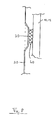
- Fig. 1 is a perspective semi-sectional view of a connecting location of a telescopic part on a crane jib configured in accordance with the invention;
- Fig. 1a is an explanatory partial section in the region of the embossments formed in Fig. 1;
- Fig. 2 is a semi-cross-section through the overlapping portion of two telescopic pans at a position adjacent to a formed embossment;
- Fig. 3 is a cross-sectional view on a magnified scale in the overlapping portion at the position of the maximum protuberance of a formed embossment;
- Fig. 3A is an enlarged cross-sectional view similar to the view of Fig. 3 showing another embodiment of the convexity wherein the convexity is welded onto a flat plate region of the inner telescopic part;
- Fig. 3B is an enlarged cross-sectional view of still another embodiment of a convexity which is a separate part welded into an aperture in the wall of the inner telescopic part;
- Fig. 3C is an enlarged cross-sectional view of yet another embodiment of an embossment with the concave side filled with reinforcing material such as foamed material;
- Fig. 4 is a semi-cross-section of the overlapping portion through the collar of an outer telescopic part at a position adjacent to a formed embossment;
- Fig. 5 is a side view of the overlapping portion of a telescopic jib bearing in accordance with the present invention;
- Fig. 6 is a cross-section of a telescopic jib bearing having embossments in the lower jib cross-section;
- Fig. 7 is a side view of a telescopic part having a slanting arrangement of elongated beads formed as embossments; and
- Fig. 8 is a cross-section through the telescopic part as shown in Fig. 7, taken along the section plane VIII-VIII.
-
- Referring now to Fig. 1 there is illustrated an embodiment of the telescopic jib bearing assembly in accordance with the invention by way of a crane jib as an example. The inner
telescopic part 20 is mounted in the outertelescopic part 10 comprising at its front end acollar 15. The overlapping portion of the twotelescopic parts embossments 30 and the sliding element orslipper 40 are better evident. - In the upper portion of the side part oriented vertically downwards of the inner
telescopic part 20 theembossments 30 in accordance with the invention are formed and juxtaposed longitudinally. -
Several embossments 30 are provided, and formed in sequence, so thatembossments 30 exist in the collar and in the overlapping portion. Thus, on further extension of the innertelescopic part 20 at least one embossment is formed, in this case, in the collar portion.
The slidingelement 40 secured in the overlapping portion on the inside of thecollar 15 or on the outside of thetelescopic part 10 is mounted longitudinally in the form of a slider band, level with the largest protuberance of theembossments 30. - For further details reference is made to a longitudinal section through the outer
telescopic part 10 shown in Fig. 1a, illustrating the slidingelement 40 mounted thereto and twoembossments 30 formed thereon, from which it is clearly evident that the embossments have convexities which are configured as very shallow cones which are able to slide over the slidingelement 40 by their relatively obtuse apexes. - Referring now to Fig. 2 there is illustrated a cross-section through one such bearing in accordance with the invention. This cross-section is disposed at a position between two formed
embossments 30 so that theembossment 30 formed on the innertelescopic part 20 is fully evident. In Fig. 2 thereference numerals section vertical side part 22 of the innertelescopic part 20 in accordance with the invention is theembossment 30 extending as a shallow cone outwardly and in contact with the slidingelement 40 by its largest protuberance. The slidingelement 40 is in turn mounted on the outertelescopic part 10 at the vertical side part, internally. - Fig. 2 shows a section in the overlapping portion of the two
telescopic parts - The stabilizing function of the
embossments 30 will now be explained with respect to the illustrations on a magnified scale in Figs. 3, 3A, 3B and 3C. These Figures illustrate sections in the overlapping portion at the location of the largest protuberance of the formedembossment 30. - The
embossment 30 is able to enhance stability simply by its presence, it also having the effect, however, that the cross-section of the innertelescopic part 20 can only buckle outwardly, but never inwardly, at these locations when subjected to a buckling load in the upper semi-box shapedsection 21. However, such a tendency to buckle is even further prevented by the design as shown in Figs. 2, 3, 3A, 3B and 3C in which the embossments can be formed to lean against the wall of the outer telescopic part via the slidingelement 40. Due to this further means of stabilization buckling can be avoided in the overlapping portion. Additional bearing locations materialize so that the required stability can be attained without the need for additional reinforcements. - The enlarged cross-sectional view of Fig. 3 shows one form of the convexity of an embossment. Figs. 3A, 3B and 3C show other embodiments.
- In Fig. 3A the
convexity 30A is a separate piece welded to a flat plate region of the innertelescopic part 20. - In Fig. 3B the convexity 30B is a separate piece welded into an opening in inner
telescopic part 20. - In Fig. 3C convexity 30C is reinforced in the concave cavity on its rear side with foamed or solid filler material.
- A further aspect of the invention is evident from the lower cross-section of the jib design as shown in Fig. 2. The base part or the telescopic parts of a telescopic jib may comprise the lower cross-sectional structure as described in the following description which enhances stability even further.
- The
lower cross-section 24 of the jib structure as shown in Fig. 2 is made up of juxtaposed shell segments. The innertelescopic part 20 comprises twosuch shell segments 25 whilst for the outertelescopic part 10 the twoshell segments 26 are illustrated. - The
shell segments section - Such shell segments curved outwardly in a circular arc are of major advantage in the load application zone, the resulting edges contributing towards the stiffness under buckling. Together with the aforementioned embossed structure of the
upper section - Referring now to Fig. 4 there is illustrated a cross-section through a telescopic jib bearing assembly in accordance with the invention in the region of the collar. In this case it is the
collar 15, in which the innertelescopic part 20 is mounted, is shown as the outermost component. This bearing arrangement in thecollar 15 serves to handle or receive all resulting forces and comprises the slidingelements 16 provided in the lower portion of thecollar 15 between it and the innertelescopic part 20, as well as in the upper corner portions the slidingelements 17. - The cross-section as shown in Fig. 4 is also located spatially adjacent to the
embossments 30 so that one thereof is evident as a whole in the upper side part portion of the innertelescopic part 20. As is evident from Fig. 2, in this case too, the support of theembossments 30 formed on the inner wall of thecollar 15 by the slidingelement 40 is discernible, and here too, thisembossment 30 as well as the support contribute towards enhancing stability as far as the buckling strength is concerned. - Referring now to Fig. 5 there is illustrated the portion of the outer
telescopic part 10 overlapping the innertelescopic part 20. Only oneembossment 30 is shown in Fig. 5 representative for all possible arrangements thereof, this embossment being located in the overlappingportion 50 in the collar. - Referring now to Fig. 6 there is illustrated a further embodiment of the present invention in a cross-sectional representation, this Figure 6 showing in turn a cross-section in the collar portion, the
collar 15 thereby being shown in part only at the locations important to explaining the arrangement. In the embodiment as shown in Fig. 6 the innertelescopic part 20 comprises on both the vertical side surface areas and on itslower part embossments 30 formed slidably mounted via slidingelements 40 on thecollar 15, i.e. a further bearing possibility being available by arranging theembossment 30 on the lower part of the cross-section. - As evident from Fig. 6 the lower cross-section is formed by a flat arrangement of segments. Such an
embodiment including embossments 30 and slidingelements 40 on the lower cross-section is, of course, also possible in the case of shell segments configured circularly in the lower cross-section portion as is evident, for example, from Figs. 2 and 4. - The
embossments 30 of the telescopic parts must not necessarily be formed as shallow cones. As already mentioned above, a spherical callote shell shape is also conceivable as well as slanting longitudinally spaced beads as shown in the side view in Fig. 7. Thetelescopic part section 20 as shown in Fig. 7 is arranged this time in the overlapping portion of two telescopic parts. As evident from Fig. 8 representing a partial cross-section taken long the location VIII-VIII in Fig. 7, the longitudinally spaced beads form embossments oriented outwardly at the locations where the slidingband 40 is arranged. In this case too, these embossments support the innertelescopic part 20 via a slidingelement 40 on the outer cross-section formed by an outertelescopic part 10 or acollar 15. - The embossments may be formed on the inner and outer telescopic part so that each supports the other; when the beads are configured on the inner and outer telescopic part they are provided to advantage so that they intersect in each case.
- The invention is defined by claim 1. The subclaims define advantageous embodiments of the invention.
Claims (11)
- A telescopic jib bearing assembly for at least two telescopic parts (10, 20), hollow in cross-section, characterized byembossments (30) formed on at least one of the telescopic parts (20), at least in overlapping portions (50) of the two telescopic parts (10, 20), said embossments (30) having convexities on one surface of the at least one telescopic part (20) and concavities on an opposite surface thereof; andbearing surfaces on one surface of the two telescopic parts (10, 20) in the overlapping portion (50) for engaging the convexities of the other telescopic part (20) in a sliding telescopic fashion.
- The telescopic jib bearing assembly of claim 1, wherein embossments (30) are provided on an inner one (20) of the two telescopic parts (10, 20) with the convexities disposed on an outside surface thereof for engaging bearing surfaces on an inside surface of the outer telescopic part (10).
- The telescopic jib bearing assembly of claim 1, wherein embossments are provided on an outer one of the two telescopic parts with the convexities disposed on an inside surface thereof for engaging bearing surfaces on an outside surface of the inner telescopic parts.
- The telescopic jib bearing assembly of claim 1, wherein embossments are provided on both the inner and outer telescopic parts with the convexities thereof engaging bearings on the opposed surface of the other of said telescopic parts.
- The telescopic jib bearing assembly of claim 1, further including a collar (15) surrounding the outer telescopic part (10) in the overlapping portion (50), said embossment (30) being provided on either the outside surface of the inner telescopic part (20) or an inside surface of the collar (15), the other one of said inner telescopic part (20) or the collar (15) having bearing surfaces for engaging the convexities of the embossments (30).
- The telescopic jib bearing assembly of one of the claims 1 to 5, wherein said telescopic parts (10, 20) comprise in cross-section an upper substantially box-shaped section (11, 21) and a lower substantially curved section connected thereto, said embossments being provided on vertical side parts of the upper box-shaped section.
- The telescopic jib bearing assembly of one of the claims 1 to 6, wherein embossments (20) are provided on the lower section (24) of the telescopic parts (10, 20).
- The telescopic jib bearing assembly of one of the claims 6 or 7, wherein the curved section (24) includes circular outwardly curved segments (25, 26) of differing predetermined radii.
- The telescopic jib bearing assembly of claims 1 to 8 wherein said embossments (30) include elongated beads slantingly oriented to a longitudinal axis of the telescopic parts (10, 20), said beads preferably intersecting each other on said inner and outer telescopic parts (10, 20).
- The telescopic jib bearing assembly of claims 1 to 8 wherein the embossments (20) are from a group of shapes consisting essentially of elongated bead shapes, conical shapes or spherical shapes.
- The telescopic jib bearing assembly of claims 1 to 10 wherein the convexity is a separate piece of material welded to a flat plate region of the inner telescopic part, and/or the convexity (30A) is a separate piece of material welded into an opening in a wall of the inner telescopic part and/or the concavity (30F) on the opposite side of the convexity is filled with a reinforcing foamed or solid material.
Applications Claiming Priority (2)
| Application Number | Priority Date | Filing Date | Title |
|---|---|---|---|
| DE19755355A DE19755355C2 (en) | 1997-12-12 | 1997-12-12 | Telescopic boom storage with embossing |
| DE19755355 | 1997-12-12 |
Publications (3)
| Publication Number | Publication Date |
|---|---|
| EP0922664A2 EP0922664A2 (en) | 1999-06-16 |
| EP0922664A3 EP0922664A3 (en) | 1999-10-20 |
| EP0922664B1 true EP0922664B1 (en) | 2003-10-15 |
Family
ID=7851747
Family Applications (1)
| Application Number | Title | Priority Date | Filing Date |
|---|---|---|---|
| EP98123089A Expired - Lifetime EP0922664B1 (en) | 1997-12-12 | 1998-12-10 | Telescopic jib bearing assembly with embossments |
Country Status (6)
| Country | Link |
|---|---|
| US (1) | US6086256A (en) |
| EP (1) | EP0922664B1 (en) |
| JP (1) | JP3342843B2 (en) |
| CA (1) | CA2255324C (en) |
| DE (2) | DE19755355C2 (en) |
| ES (1) | ES2209042T3 (en) |
Cited By (1)
| Publication number | Priority date | Publication date | Assignee | Title |
|---|---|---|---|---|
| CN1827518B (en) * | 2005-03-01 | 2010-11-03 | 格罗夫美国有限责任公司 | Adaptive sliding bearing of telescopic crane arm, sliding bearing and assembly |
Families Citing this family (12)
| Publication number | Priority date | Publication date | Assignee | Title |
|---|---|---|---|---|
| DE19948830B4 (en) * | 1999-10-06 | 2005-11-24 | Terex-Demag Gmbh & Co. Kg | Telescopic boom for cranes |
| US6601719B2 (en) | 2001-09-21 | 2003-08-05 | Link-Belt Construction Equipment Co., L.P., Lllp | Locking and latching system for a telescoping boom |
| DE102005009348B4 (en) * | 2005-03-01 | 2013-05-29 | Manitowoc Crane Group France Sas | Adaptable sliding bearing for telescopic crane jib |
| JP5625309B2 (en) * | 2009-10-13 | 2014-11-19 | コベルコクレーン株式会社 | boom |
| US8245456B2 (en) * | 2010-10-19 | 2012-08-21 | Ed Anderson | Boom assembly |
| US8678210B1 (en) * | 2010-11-17 | 2014-03-25 | Link-Belt Construction Equipment Co., L.P., Lllp | Telescoping boom assembly with base section having primary shell and secondary formed shell |
| US8540438B1 (en) | 2011-03-24 | 2013-09-24 | CamMate Systems. Inc. | Systems and methods for positioning a camera crane |
| US8333520B1 (en) | 2011-03-24 | 2012-12-18 | CamMate Systems, Inc. | Systems and methods for detecting an imbalance of a camera crane |
| US9290363B2 (en) * | 2011-07-21 | 2016-03-22 | Manitowoc Crane Companies, Llc | Tailor welded panel beam for construction machine and method of manufacturing |
| DE102019107456A1 (en) * | 2019-03-22 | 2020-09-24 | Schwing Gmbh | Articulated mast with mast segments and method for producing a mast segment |
| US20220002128A1 (en) * | 2020-04-09 | 2022-01-06 | Chapman/Leonard Studio Equipment, Inc. | Telescoping electric camera crane |
| US11864652B1 (en) * | 2022-06-29 | 2024-01-09 | Martas Precision Slide Co., Ltd. | Geometric reinforcing structure for slide rail |
Family Cites Families (17)
| Publication number | Priority date | Publication date | Assignee | Title |
|---|---|---|---|---|
| US2949692A (en) * | 1958-02-24 | 1960-08-23 | Bromo Mint Company Inc | Construction toy |
| DE1281651C2 (en) * | 1966-06-30 | 1975-02-13 | Leo Gottwald KG, 4000 Düsseldorf | TELESCOPIC RETRACTABLE AND EXTENDABLE CRANE BOOM |
| DE2116842A1 (en) * | 1970-04-08 | 1971-10-21 | J Tranchero | Mobile crane designed for mounting on motor vehicles with three hydraulically controlled lifting stages |
| US3719403A (en) * | 1970-11-17 | 1973-03-06 | Kidde & Co Walter | Crane boom having wear pads |
| FR2255251B1 (en) * | 1973-12-20 | 1976-11-19 | Creusot Loire | |
| US3931698A (en) * | 1974-11-20 | 1976-01-13 | The Warner & Swasey Company | Center guided crane boom |
| US4045936A (en) * | 1976-04-26 | 1977-09-06 | Bucyrus-Erie Company | Telescopic boom with sections of beam and truss construction |
| US4168008A (en) * | 1978-02-23 | 1979-09-18 | Granryd Tod G | Telescopic crane boom having corrugated boom sections |
| US4337601A (en) * | 1980-04-24 | 1982-07-06 | Harnischfeger Corporation | High-strength light-weight boom section for telescopic crane boom |
| US4459786A (en) * | 1981-10-27 | 1984-07-17 | Ro Corporation | Longitudinally bowed transversely polygonal boom for cranes and the like |
| US4459768A (en) * | 1983-01-31 | 1984-07-17 | J. I. Case Company | Bucket design |
| SE456820B (en) * | 1984-03-12 | 1988-11-07 | Oesa Ab | DEVICE ON TELESCOPE ARMS |
| USD299079S (en) | 1986-02-07 | 1988-12-20 | Kidde, Inc. | Embossed telescopic crane boom |
| USD299179S (en) | 1986-02-07 | 1988-12-27 | Kidde, Inc. | Embossed telescopic crane boom section |
| SE501064C2 (en) * | 1993-12-10 | 1994-10-31 | Hiab Ab | Tray for controlling two mutually moving parts |
| DE9402692U1 (en) * | 1994-02-18 | 1994-04-14 | Ec Engineering + Consulting Spezialmaschinen Gmbh, 89079 Ulm | Boom profile |
| US5624047A (en) * | 1995-04-24 | 1997-04-29 | General Electric Company | Telescoping mast with zero clearance for refueling machine |
-
1997
- 1997-12-12 DE DE19755355A patent/DE19755355C2/en not_active Expired - Fee Related
-
1998
- 1998-12-10 DE DE69818950T patent/DE69818950T2/en not_active Expired - Lifetime
- 1998-12-10 EP EP98123089A patent/EP0922664B1/en not_active Expired - Lifetime
- 1998-12-10 ES ES98123089T patent/ES2209042T3/en not_active Expired - Lifetime
- 1998-12-10 CA CA002255324A patent/CA2255324C/en not_active Expired - Fee Related
- 1998-12-11 US US09/209,750 patent/US6086256A/en not_active Expired - Lifetime
- 1998-12-11 JP JP37782398A patent/JP3342843B2/en not_active Expired - Fee Related
Cited By (1)
| Publication number | Priority date | Publication date | Assignee | Title |
|---|---|---|---|---|
| CN1827518B (en) * | 2005-03-01 | 2010-11-03 | 格罗夫美国有限责任公司 | Adaptive sliding bearing of telescopic crane arm, sliding bearing and assembly |
Also Published As
| Publication number | Publication date |
|---|---|
| EP0922664A3 (en) | 1999-10-20 |
| DE69818950T2 (en) | 2004-08-12 |
| CA2255324A1 (en) | 1999-06-12 |
| DE69818950D1 (en) | 2003-11-20 |
| US6086256A (en) | 2000-07-11 |
| JPH11322275A (en) | 1999-11-24 |
| DE19755355A1 (en) | 1999-06-24 |
| CA2255324C (en) | 2006-06-13 |
| EP0922664A2 (en) | 1999-06-16 |
| DE19755355C2 (en) | 1999-12-23 |
| JP3342843B2 (en) | 2002-11-11 |
| ES2209042T3 (en) | 2004-06-16 |
Similar Documents
| Publication | Publication Date | Title |
|---|---|---|
| CA2255324C (en) | Telescopic jib bearing assembly with embossments | |
| EP0814050B1 (en) | Telescopic jib for vehicular cranes | |
| US4168008A (en) | Telescopic crane boom having corrugated boom sections | |
| CA2198331C (en) | A device for guiding a telescopic part for a telescopic boom | |
| EP0903316B1 (en) | Slide mount for telescope parts | |
| US6098824A (en) | Telescopic crane boom section and a process for making sure | |
| JP4741527B2 (en) | Jib part of a telescopic crane having a section having a smaller curvature and a section having a greater curvature at the upper and lower contours of the cross section | |
| US20030106871A1 (en) | Telescopic jib for a vehicular crane | |
| US7878349B2 (en) | Profile shape for a crane boom | |
| EP2078693A1 (en) | Telescopic boom | |
| JP2018193247A (en) | Telescopic boom and mobile crane | |
| US9718654B2 (en) | Telescopic boom | |
| CA2457972A1 (en) | Boom | |
| CA2697301C (en) | Profile shape for a crane boom | |
| CA2697304A1 (en) | Profile shape for a crane boom | |
| JP2018080020A (en) | Extendable boom | |
| CN219753464U (en) | Steel column reducing node with small bottom and large top | |
| CN217102936U (en) | Die forging formula slope hydro-cylinder fixed bolster | |
| CN211684630U (en) | Mounting bracket and vehicle of battery package | |
| KR100283092B1 (en) | Construction of Crane Crane Boom for Hydraulic Crane_ | |
| JPH09227095A (en) | Tilt bracket and outer mast | |
| KR980001277A (en) | Pedestal reinforcement structure of vehicle cup holder | |
| JPH0262479B2 (en) |
Legal Events
| Date | Code | Title | Description |
|---|---|---|---|
| PUAI | Public reference made under article 153(3) epc to a published international application that has entered the european phase |
Free format text: ORIGINAL CODE: 0009012 |
|
| AK | Designated contracting states |
Kind code of ref document: A2 Designated state(s): DE ES FR GB IT |
|
| AX | Request for extension of the european patent |
Free format text: AL;LT;LV;MK;RO;SI |
|
| PUAL | Search report despatched |
Free format text: ORIGINAL CODE: 0009013 |
|
| AK | Designated contracting states |
Kind code of ref document: A3 Designated state(s): AT BE CH CY DE DK ES FI FR GB GR IE IT LI LU MC NL PT SE |
|
| AX | Request for extension of the european patent |
Free format text: AL;LT;LV;MK;RO;SI |
|
| 17P | Request for examination filed |
Effective date: 19991124 |
|
| AKX | Designation fees paid |
Free format text: DE ES FR GB IT |
|
| GRAH | Despatch of communication of intention to grant a patent |
Free format text: ORIGINAL CODE: EPIDOS IGRA |
|
| GRAS | Grant fee paid |
Free format text: ORIGINAL CODE: EPIDOSNIGR3 |
|
| GRAA | (expected) grant |
Free format text: ORIGINAL CODE: 0009210 |
|
| AK | Designated contracting states |
Kind code of ref document: B1 Designated state(s): DE ES FR GB IT |
|
| REG | Reference to a national code |
Ref country code: GB Ref legal event code: FG4D |
|
| REF | Corresponds to: |
Ref document number: 69818950 Country of ref document: DE Date of ref document: 20031120 Kind code of ref document: P |
|
| REG | Reference to a national code |
Ref country code: ES Ref legal event code: FG2A Ref document number: 2209042 Country of ref document: ES Kind code of ref document: T3 |
|
| ET | Fr: translation filed | ||
| PLBE | No opposition filed within time limit |
Free format text: ORIGINAL CODE: 0009261 |
|
| STAA | Information on the status of an ep patent application or granted ep patent |
Free format text: STATUS: NO OPPOSITION FILED WITHIN TIME LIMIT |
|
| 26N | No opposition filed |
Effective date: 20040716 |
|
| REG | Reference to a national code |
Ref country code: GB Ref legal event code: 732E Free format text: REGISTERED BETWEEN 20110915 AND 20110921 |
|
| REG | Reference to a national code |
Ref country code: FR Ref legal event code: TP Owner name: MANITOWOC CRANE GROUP FRANCE, FR Effective date: 20110920 |
|
| REG | Reference to a national code |
Ref country code: ES Ref legal event code: PC2A Owner name: MANITOWOC CRANE GROUP FRANCE SAS Effective date: 20111027 |
|
| REG | Reference to a national code |
Ref country code: DE Ref legal event code: R082 Ref document number: 69818950 Country of ref document: DE Representative=s name: SCHWABE SANDMAIR MARX, DE |
|
| REG | Reference to a national code |
Ref country code: DE Ref legal event code: R082 Ref document number: 69818950 Country of ref document: DE Representative=s name: SCHWABE SANDMAIR MARX PATENTANWAELTE RECHTSANW, DE Effective date: 20120330 Ref country code: DE Ref legal event code: R082 Ref document number: 69818950 Country of ref document: DE Representative=s name: SCHWABE SANDMAIR MARX, DE Effective date: 20120330 Ref country code: DE Ref legal event code: R081 Ref document number: 69818950 Country of ref document: DE Owner name: MANITOWOC CRANE GROUP FRANCE SAS, FR Free format text: FORMER OWNER: GROVE U.S. LLC, SHADY GROVE, US Effective date: 20120330 Ref country code: DE Ref legal event code: R081 Ref document number: 69818950 Country of ref document: DE Owner name: MANITOWOC CRANE GROUP FRANCE SAS, FR Free format text: FORMER OWNER: GROVE U.S. LLC, SHADY GROVE, PA., US Effective date: 20120330 |
|
| PGFP | Annual fee paid to national office [announced via postgrant information from national office to epo] |
Ref country code: GB Payment date: 20140627 Year of fee payment: 16 |
|
| PGFP | Annual fee paid to national office [announced via postgrant information from national office to epo] |
Ref country code: DE Payment date: 20141211 Year of fee payment: 17 Ref country code: ES Payment date: 20141226 Year of fee payment: 17 |
|
| PGFP | Annual fee paid to national office [announced via postgrant information from national office to epo] |
Ref country code: FR Payment date: 20141219 Year of fee payment: 17 |
|
| REG | Reference to a national code |
Ref country code: DE Ref legal event code: R082 Ref document number: 69818950 Country of ref document: DE Representative=s name: SCHWABE SANDMAIR MARX, DE |
|
| REG | Reference to a national code |
Ref country code: DE Ref legal event code: R082 Ref document number: 69818950 Country of ref document: DE Representative=s name: SCHWABE SANDMAIR MARX PATENTANWAELTE RECHTSANW, DE Effective date: 20150317 Ref country code: DE Ref legal event code: R082 Ref document number: 69818950 Country of ref document: DE Representative=s name: SCHWABE SANDMAIR MARX, DE Effective date: 20150317 Ref country code: DE Ref legal event code: R081 Ref document number: 69818950 Country of ref document: DE Owner name: MANITOWOC CRANE GROUP FRANCE SAS, FR Free format text: FORMER OWNER: MANITOWOC CRANE GROUP FRANCE SAS, ECULLY, FR Effective date: 20150317 |
|
| PGFP | Annual fee paid to national office [announced via postgrant information from national office to epo] |
Ref country code: IT Payment date: 20141223 Year of fee payment: 17 |
|
| GBPC | Gb: european patent ceased through non-payment of renewal fee |
Effective date: 20141210 |
|
| PG25 | Lapsed in a contracting state [announced via postgrant information from national office to epo] |
Ref country code: GB Free format text: LAPSE BECAUSE OF NON-PAYMENT OF DUE FEES Effective date: 20141210 |
|
| REG | Reference to a national code |
Ref country code: DE Ref legal event code: R119 Ref document number: 69818950 Country of ref document: DE |
|
| REG | Reference to a national code |
Ref country code: FR Ref legal event code: ST Effective date: 20160831 |
|
| PG25 | Lapsed in a contracting state [announced via postgrant information from national office to epo] |
Ref country code: DE Free format text: LAPSE BECAUSE OF NON-PAYMENT OF DUE FEES Effective date: 20160701 |
|
| PG25 | Lapsed in a contracting state [announced via postgrant information from national office to epo] |
Ref country code: FR Free format text: LAPSE BECAUSE OF NON-PAYMENT OF DUE FEES Effective date: 20151231 |
|
| PG25 | Lapsed in a contracting state [announced via postgrant information from national office to epo] |
Ref country code: IT Free format text: LAPSE BECAUSE OF NON-PAYMENT OF DUE FEES Effective date: 20151210 |
|
| REG | Reference to a national code |
Ref country code: ES Ref legal event code: FD2A Effective date: 20170126 |
|
| PG25 | Lapsed in a contracting state [announced via postgrant information from national office to epo] |
Ref country code: ES Free format text: LAPSE BECAUSE OF NON-PAYMENT OF DUE FEES Effective date: 20151211 |