EP0922516B1 - Method and equipment for processing carbon bodies - Google Patents
Method and equipment for processing carbon bodies Download PDFInfo
- Publication number
- EP0922516B1 EP0922516B1 EP98119212A EP98119212A EP0922516B1 EP 0922516 B1 EP0922516 B1 EP 0922516B1 EP 98119212 A EP98119212 A EP 98119212A EP 98119212 A EP98119212 A EP 98119212A EP 0922516 B1 EP0922516 B1 EP 0922516B1
- Authority
- EP
- European Patent Office
- Prior art keywords
- accordance
- processing
- holes
- axis
- cutting elements
- Prior art date
- Legal status (The legal status is an assumption and is not a legal conclusion. Google has not performed a legal analysis and makes no representation as to the accuracy of the status listed.)
- Expired - Lifetime
Links
- 238000012545 processing Methods 0.000 title claims description 63
- OKTJSMMVPCPJKN-UHFFFAOYSA-N Carbon Chemical compound [C] OKTJSMMVPCPJKN-UHFFFAOYSA-N 0.000 title claims description 56
- 229910052799 carbon Inorganic materials 0.000 title claims description 56
- 238000000034 method Methods 0.000 title claims description 13
- 238000005520 cutting process Methods 0.000 claims description 40
- 210000002445 nipple Anatomy 0.000 claims description 27
- 238000001354 calcination Methods 0.000 claims description 11
- 230000015572 biosynthetic process Effects 0.000 claims description 10
- 238000004519 manufacturing process Methods 0.000 claims description 6
- 239000004411 aluminium Substances 0.000 claims description 5
- 229910052782 aluminium Inorganic materials 0.000 claims description 5
- XAGFODPZIPBFFR-UHFFFAOYSA-N aluminium Chemical compound [Al] XAGFODPZIPBFFR-UHFFFAOYSA-N 0.000 claims description 5
- 239000000428 dust Substances 0.000 claims description 5
- 239000002245 particle Substances 0.000 claims description 3
- 229910010293 ceramic material Inorganic materials 0.000 claims description 2
- 229910003460 diamond Inorganic materials 0.000 claims description 2
- 239000010432 diamond Substances 0.000 claims description 2
- 229910052751 metal Inorganic materials 0.000 claims description 2
- 239000002184 metal Substances 0.000 claims description 2
- 238000003754 machining Methods 0.000 description 8
- 239000000463 material Substances 0.000 description 6
- 229910000831 Steel Inorganic materials 0.000 description 4
- 238000004140 cleaning Methods 0.000 description 4
- 239000010959 steel Substances 0.000 description 4
- 238000012360 testing method Methods 0.000 description 4
- 229910001018 Cast iron Inorganic materials 0.000 description 2
- 238000005868 electrolysis reaction Methods 0.000 description 2
- 230000002093 peripheral effect Effects 0.000 description 2
- 238000007664 blowing Methods 0.000 description 1
- 239000003575 carbonaceous material Substances 0.000 description 1
- 230000000052 comparative effect Effects 0.000 description 1
- 239000002826 coolant Substances 0.000 description 1
- 238000005553 drilling Methods 0.000 description 1
- 238000005516 engineering process Methods 0.000 description 1
- 230000002349 favourable effect Effects 0.000 description 1
- 238000010304 firing Methods 0.000 description 1
- 238000007689 inspection Methods 0.000 description 1
- 239000000314 lubricant Substances 0.000 description 1
- 238000012423 maintenance Methods 0.000 description 1
- 238000003801 milling Methods 0.000 description 1
- 238000012856 packing Methods 0.000 description 1
- 239000000725 suspension Substances 0.000 description 1
Images



Classifications
-
- B—PERFORMING OPERATIONS; TRANSPORTING
- B23—MACHINE TOOLS; METAL-WORKING NOT OTHERWISE PROVIDED FOR
- B23B—TURNING; BORING
- B23B51/00—Tools for drilling machines
- B23B51/0018—Drills for enlarging a hole
-
- B—PERFORMING OPERATIONS; TRANSPORTING
- B23—MACHINE TOOLS; METAL-WORKING NOT OTHERWISE PROVIDED FOR
- B23C—MILLING
- B23C5/00—Milling-cutters
- B23C5/02—Milling-cutters characterised by the shape of the cutter
- B23C5/12—Cutters specially designed for producing particular profiles
-
- Y—GENERAL TAGGING OF NEW TECHNOLOGICAL DEVELOPMENTS; GENERAL TAGGING OF CROSS-SECTIONAL TECHNOLOGIES SPANNING OVER SEVERAL SECTIONS OF THE IPC; TECHNICAL SUBJECTS COVERED BY FORMER USPC CROSS-REFERENCE ART COLLECTIONS [XRACs] AND DIGESTS
- Y10—TECHNICAL SUBJECTS COVERED BY FORMER USPC
- Y10T—TECHNICAL SUBJECTS COVERED BY FORMER US CLASSIFICATION
- Y10T407/00—Cutters, for shaping
- Y10T407/19—Rotary cutting tool
- Y10T407/1906—Rotary cutting tool including holder [i.e., head] having seat for inserted tool
- Y10T407/1908—Face or end mill
- Y10T407/1924—Specified tool shape
-
- Y—GENERAL TAGGING OF NEW TECHNOLOGICAL DEVELOPMENTS; GENERAL TAGGING OF CROSS-SECTIONAL TECHNOLOGIES SPANNING OVER SEVERAL SECTIONS OF THE IPC; TECHNICAL SUBJECTS COVERED BY FORMER USPC CROSS-REFERENCE ART COLLECTIONS [XRACs] AND DIGESTS
- Y10—TECHNICAL SUBJECTS COVERED BY FORMER USPC
- Y10T—TECHNICAL SUBJECTS COVERED BY FORMER US CLASSIFICATION
- Y10T408/00—Cutting by use of rotating axially moving tool
- Y10T408/03—Processes
-
- Y—GENERAL TAGGING OF NEW TECHNOLOGICAL DEVELOPMENTS; GENERAL TAGGING OF CROSS-SECTIONAL TECHNOLOGIES SPANNING OVER SEVERAL SECTIONS OF THE IPC; TECHNICAL SUBJECTS COVERED BY FORMER USPC CROSS-REFERENCE ART COLLECTIONS [XRACs] AND DIGESTS
- Y10—TECHNICAL SUBJECTS COVERED BY FORMER USPC
- Y10T—TECHNICAL SUBJECTS COVERED BY FORMER US CLASSIFICATION
- Y10T408/00—Cutting by use of rotating axially moving tool
- Y10T408/89—Tool or Tool with support
- Y10T408/905—Having stepped cutting edges
-
- Y—GENERAL TAGGING OF NEW TECHNOLOGICAL DEVELOPMENTS; GENERAL TAGGING OF CROSS-SECTIONAL TECHNOLOGIES SPANNING OVER SEVERAL SECTIONS OF THE IPC; TECHNICAL SUBJECTS COVERED BY FORMER USPC CROSS-REFERENCE ART COLLECTIONS [XRACs] AND DIGESTS
- Y10—TECHNICAL SUBJECTS COVERED BY FORMER USPC
- Y10T—TECHNICAL SUBJECTS COVERED BY FORMER US CLASSIFICATION
- Y10T408/00—Cutting by use of rotating axially moving tool
- Y10T408/89—Tool or Tool with support
- Y10T408/905—Having stepped cutting edges
- Y10T408/906—Axially spaced
-
- Y—GENERAL TAGGING OF NEW TECHNOLOGICAL DEVELOPMENTS; GENERAL TAGGING OF CROSS-SECTIONAL TECHNOLOGIES SPANNING OVER SEVERAL SECTIONS OF THE IPC; TECHNICAL SUBJECTS COVERED BY FORMER USPC CROSS-REFERENCE ART COLLECTIONS [XRACs] AND DIGESTS
- Y10—TECHNICAL SUBJECTS COVERED BY FORMER USPC
- Y10T—TECHNICAL SUBJECTS COVERED BY FORMER US CLASSIFICATION
- Y10T82/00—Turning
- Y10T82/12—Radially moving rotating tool inside bore
- Y10T82/125—Tool simultaneously moving axially
-
- Y—GENERAL TAGGING OF NEW TECHNOLOGICAL DEVELOPMENTS; GENERAL TAGGING OF CROSS-SECTIONAL TECHNOLOGIES SPANNING OVER SEVERAL SECTIONS OF THE IPC; TECHNICAL SUBJECTS COVERED BY FORMER USPC CROSS-REFERENCE ART COLLECTIONS [XRACs] AND DIGESTS
- Y10—TECHNICAL SUBJECTS COVERED BY FORMER USPC
- Y10T—TECHNICAL SUBJECTS COVERED BY FORMER US CLASSIFICATION
- Y10T82/00—Turning
- Y10T82/12—Radially moving rotating tool inside bore
- Y10T82/125—Tool simultaneously moving axially
- Y10T82/128—Pivoted to tool-carrier
Definitions
- the present invention concerns a method and equipment with a processing tool for the processing of carbon bodies, such as formation of holes in carbon bodies, in particular nipple holes in anodes for use in electrolytic cells for the production of aluminium.
- anodes which comprise a prebaked or calcined carbon body fastened to an anode hanger.
- the anode hanger usually consists of an upper part, an anode rod made of aluminium and a lower part comprising. a yoke with steel nipples which extend downwards.
- the carbon body is fastened to the steel part of the anode hanger using a cast iron or monolithic lining material joint. More specifically, the joint between the carbon body and the steel part is formed by the nipples in the steel part first being arranged so that they extend downwards into holes in the carbon body and then the holes being filled with molten cast iron or having monolithic lining material pressed into them.
- the holes in the carbon body are formed in the traditional manner during the forming of the carbon bodies, the so-called “green carbon", before the calcination process (prebaking process).
- the green carbon must be stacked in a special way in the calcination furnaces to avoid creep and deformation of the holes. This special stacking results in additional work and reduced calcination capacity, i.e. reduced productivity.
- nipple holes are associated with large density gradients and many small cracks in the carbon body around the nipple hole.
- the cracks will result in a high electrical contact resistance, which is not very desirable during the electrolysis process as the increase in resistance can lead to an increase in the temperature in the joint between the anode and the nipple.
- nipple holes Another disadvantage of preforming the nipple holes is that there are restrictions to the geometry which can be formed with this technique as they are usually formed using projections in the vibration mould which must be provided with a certain taper so that they can be withdrawn from the body when the stamping has finished. If undercut or conical nipple holes are to be formed, which will gradually become more common, the hole must be processed further.
- FR 2 590 911 shows a two-part cleaning tool for nipple holes in which a first, outer part is designed to clean grooves in the walls of the hole while a second part is designed to smooth the peripheral surface and base of the hole.
- the latter part is driven by a rotating shaft while the first part is arranged coaxially and supported freely in relation to the shaft.
- This equipment which, among other things, is designed to clean grooves in the walls of the hole by means of axial motion, will be limited to cleaning preformed holes.
- EP 0 764 728 A 1 shows equipment for processing three nipple holes in one anode.
- the equipment comprises a centring device for centring an anode with preformed holes, a liftable/lowerable support for the anode and three downward-facing spindles each with its own milling head for processing the anode's holes.
- EP 0742072 A discloses an equipment for machining objects where a machine tool can be moved in three axis of movement. This reference does not disclose an equipment provided with a processing tool suitable for the processing of calcinated carbon bodies.
- the present invention represents a method and equipment for the formation of holes in carbon bodies after they have been calcined, whereby the geometry of the holes can be formed with a high degree of precision and where the wear on the equipment is minimal. Further, the equipment may also serve to remove excess material of the surface of the carbon bodies, such as gradening and smoothening.
- the present invention makes it possible to omit the preforming of nipple holes in carbon bodies in the "green state". By omitting the preforming of the holes, the vibration time in connection with the formation of the carbon body in the "green state” is reduced and the current problems of density variations and cracks around nipple holes can be avoided.
- the present invention results in great savings during calcination as the positioning in the furnace can be simplified because the carbon bodies have no nipple holes which can creep. A reduction in the positioning time will contribute to an increase in the capacity of the furnace.
- the present invention will also mean that the cassettes in the furnace can be made fuller (increase in production) as there is no need to take into consideration how the anodes are arranged. Moreover, the number of carbon bodies which must be rejected after calcination will be reduced as they have a simpler geometric form and are therefore less subject to deviations. Any carbon bodies which are destroyed during calcination as a result of crack formation, etc. will represent rejects at a lower cost level than previously because less work was done on them before the calcination.
- burdensome operations such as cleaning/alignment of nipple holes after calcination can be eliminated. These are operations which are burdensome when performed manually and which are also associated with the generation of fine dust and noise.
- a calcined carbon body can now rapidly be adapted to different designs of anode hangers so that reserve stocks of anode carbon can be reduced.
- holes of various geometries such as undercut (conical) or oval holes or holes with threads/tracks, may be formed simply and rapidly.
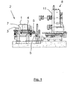
- the positioning device can position the carbon body in relation to a processing station 8 with a machining unit 11 and is designed to be swung 90 degrees around a shaft 5, for example using a linear motor (not shown) connected with an arm 6.
- a linear motor (not shown) connected with an arm 6.
- the linear motor When the linear motor is activated, the arm moves in a transverse direction in towards the conveyor track and the positioning device with the carbon body 1 swings up so that the horizontal support surface 7 is placed in a vertical position, see figure 2.
- the machining unit 11 which is shown here generally comprises one processing tool 9 mounted on a spindle 10, but several tools with associated spindles may also be used. It is expedient for the processing of one anode with three nipple holes to take place using three spindles working in parallel. In the embodiment shown, the spindle is arranged for rotation around a horizontal axis.
- the machining unit 11 is supported on a base 12 and has a chassis 13 designed to move the machining unit in the horizontal plane, which makes it possible to machine in the depth and longitudinal directions of the carbon body.
- the spindle 10 is designed to move in the vertical direction.
- the processing station 8 may have a programmable control unit (not shown) so that the processing tool 9, using the chassis and the freedom of movement of the spindle, can assume all positions in both the horizontal plane and the vertical direction.
- the processing station may comprise means (not shown) which determine the form and position of the carbon body. Information on this may be included in the machine's control unit, which uses this information in connection with processing or the choice of processing program. Programmable machines such as CNC machines are well-known to machining specialists and the actual control for the machining unit will not, therefore, be described in further detail here.
- the processing tool 9 is mounted on the spindle 10.
- a yielding sheath 14 can be placed around the processing tool.
- the sheath is fastened to the machining unit 11 on one side and has a hole in the other side.
- the spindle with the processing tool is moved forwards towards the carbon body.
- the sheath is then brought into contact with and forms a seal against the surface of the carbon body.
- the inner space of the sheath can be connected to a suction device (not shown) so that particles and any dust formed during the processing is extracted from the processing location.
- the processing tool itself may comprise means for the supply of compressed air which contributes to blowing particles and dust out of the hole which is being processed.
- the sheath may comprise a bellows or similar and may have an actuator/linear motor 15 or a spring device (not shown) which contributes to bringing the sheath into contact with and forming a seal against the carbon body.
- processing tool is shown in an outer and a lower position, as shown by the dotted lines in the figures.
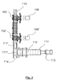
- Figure 3 shows, seen from above, a processing line with two processing stations 108, 108'.
- Positioning devices 102, 102' are arranged in connection with the processing stations and position the carbon bodies in relation to the processing stations.
- the carbon bodies 111 which are to be processed may, for example, be fed in on a conveyor track 112 by means of a truck 113 or similar at the entrance to the conveyor track.
- the exit of the conveyor track 112 may be arranged in such a way that the carbon bodies 111', 111" are fed from here onto a second conveying track 114 which runs through the positioning devices 102, 102'.
- Processed carbon bodies 115 are conveyed from the processing stations using the conveyor track 114 to a store which is not shown. It should be understood that the processing line can be operated so that only one processing station is in operation at a time. This makes it possible to perform inspections/maintenance on the station which is not in operation.
- both stations can run simultaneously in such a way that the carbon bodies which are not processed by the first station 108' are processed by the subsequent station 108.
- the processing stations may be equipped with different tools and also be programmed differently for processing of carbon bodies for different types of suspension (anode hangers).
- FIGS 4a, 4b and 5 show a processing tool which can be used as part of the equipment.
- the tool shown in figures 4a and 4b comprises a cutting head 20 with a mounting part 24 and three arms 21, 22, 23.
- the mounting part may be designed with internal threads or be designed in any other expedient manner for connection to the spindle 10.
- the arms have a divergent form so that the extent of the arms in the radial direction increases towards the outer end of the cutting head.
- the arms have cutting elements 43, 44, 45 at their peripheral surfaces and cutting elements 40, 41, 42 at their axial surfaces.
- the cutting elements may expediently be formed of ceramic material, hard metal, diamond (polycrystalline) or any other known material which is suitable for the purpose.
- the cutting elements can be displaced regarding their mounting in the arms (asymmetric positioned) so that, during processing, the cutting elements will work in positions which are slightly displaced in relation to one another.
- Figure 5 shows a cross-section of the cutting head shown in Figures 4a and 4b.
- the cutting head shown here comprises a channel 37 and nozzle 36 for the supply of compressed air to the base of the nipple hole.
- the compressed air contributes to transporting removed materials such as shavings which are produced during processing out of the hole.
- the compressed air supply is used centrally through the tool while the shavings transport will take place externally in relation to the tool.
- this cutting head is designed to be able to process conical nipple holes.
- the figure also shows a section through a carbon body 1 with a nipple hole 34 formed using the tool.
- the hole has a cylindrical hole surface 31. This is generally formed by cutting elements which are located in the area 32' on the cutting head while, during processing, the cutting head has been subject to rotation around a fixed axis.
- the hole surface 32 is conical and diverges towards the base of the hole.
- This surface is formed by the same cutting elements as stated above (32') but here the cutting head has been subject to planetary motion in its lower position, i.e. the cutting head's axis of rotation has undergone circular motion.
- the hole will be cylindrical with the exception of the round-off 30 formed by cutting elements at the part 30'.
- the cutting head it is possible to use the cutting head to form cylindrical holes with diameters greater than the diameter of the cutting head by the axis of rotation 35 of the cutting head following a circular motion throughout processing, i.e. the axis of rotation is moved so that it continuously forms a generatrix for a cylinder surface.
- the hole By giving the axis of rotation 35 of the cutting head increased circular motion when the cutting head is in its lower position, the hole can be given a conical shape. If the hole is to have an oval shape, the above circular motion is replaced with an oval or elliptical motion. It should be noted here that the axis of rotation of the cutting head can also be designed to follow other curve forms if required.
- holes which are to have a diameter which is equal to or greater than the diameter of the cutting head and to give these holes a cylindrical or conical shape.
- the holes may also be given an oval shape.
- the holes may be formed with a plane base using cutting elements mounted in the axial part 33' of the arms.
- the axial areas of the arms may be formed in another way, for example they may be rounded or they may comprise cutting elements which produce a countersunk central part of the hole if this is required.
- a processing tool with a radial cutting element which extends outwards (not shown) is used for the formation of threads/tracks in the hole.
- threads can even be processed in non-cylindrical holes.
- Tests carried out show that the proposed processing tool is subject to minimal wear during the processing of carbon bodies and the requirements for the precision and quality of the hole are met. It has been shown that the processing tool cuts the carbon material without chipping or crack formation and the use of any lubricant/coolant has been shown to be superfluous.
- Shavings produced during processing are relatively coarse-grained at favourable feed and cutting speeds and therefore little fine dust is generated.
- a cycle time of approximately 74 seconds was achieved for processing (drilling and coning) an anode with three nipple holes.
- the nipple holes had a diameter of 160 mm and depth of 110 mm with coning in the base.
- control of the processing station may in addition involve that the surface of the carbon body is smoothened with respect to possible grades and uneveness.
- the carbon body may possibly be turned in an appropriate manner (not shown in the figures) for the processing of other surface sides of the body.
- the processing as described above may be performed by mutual motion between the tool and the carbon body. Alternatively, the carbon body may be moved with respect to the processing tool (not shown).
Landscapes
- Engineering & Computer Science (AREA)
- Mechanical Engineering (AREA)
- Electrical Discharge Machining, Electrochemical Machining, And Combined Machining (AREA)
- Electrolytic Production Of Metals (AREA)
- Processing Of Stones Or Stones Resemblance Materials (AREA)
Description
- The present invention concerns a method and equipment with a processing tool for the processing of carbon bodies, such as formation of holes in carbon bodies, in particular nipple holes in anodes for use in electrolytic cells for the production of aluminium.
- In modern electrolysis plants for the production of aluminium, anodes are used which comprise a prebaked or calcined carbon body fastened to an anode hanger. The anode hanger usually consists of an upper part, an anode rod made of aluminium and a lower part comprising. a yoke with steel nipples which extend downwards.
- The carbon body is fastened to the steel part of the anode hanger using a cast iron or monolithic lining material joint. More specifically, the joint between the carbon body and the steel part is formed by the nipples in the steel part first being arranged so that they extend downwards into holes in the carbon body and then the holes being filled with molten cast iron or having monolithic lining material pressed into them.
- The holes in the carbon body are formed in the traditional manner during the forming of the carbon bodies, the so-called "green carbon", before the calcination process (prebaking process).
- This results in the following disadvantages:
- The green carbon must be stacked in a special way in the calcination furnaces to avoid creep and deformation of the holes. This special stacking results in additional work and reduced calcination capacity, i.e. reduced productivity.
- However, even if the precautions mentioned are taken, some holes will still be deformed and, consequently, some carbon bodies will be unusable. The proportion of rejects may be as much as 10% or more in some cases.
- Another problem in connection with the calcination of carbon bodies with preformed holes is that the packing material can burn fast to the walls of the holes.
- Other disadvantages are that preformed nipple holes are associated with large density gradients and many small cracks in the carbon body around the nipple hole. The cracks will result in a high electrical contact resistance, which is not very desirable during the electrolysis process as the increase in resistance can lead to an increase in the temperature in the joint between the anode and the nipple.
- Another disadvantage of preforming the nipple holes is that there are restrictions to the geometry which can be formed with this technique as they are usually formed using projections in the vibration mould which must be provided with a certain taper so that they can be withdrawn from the body when the stamping has finished. If undercut or conical nipple holes are to be formed, which will gradually become more common, the hole must be processed further.
- Several solutions are proposed for cleaning the nipple holes of an anode after calcination. For example,
FR 2 590 911 shows a two-part cleaning tool for nipple holes in which a first, outer part is designed to clean grooves in the walls of the hole while a second part is designed to smooth the peripheral surface and base of the hole. The latter part is driven by a rotating shaft while the first part is arranged coaxially and supported freely in relation to the shaft. This equipment, which, among other things, is designed to clean grooves in the walls of the hole by means of axial motion, will be limited to cleaning preformed holes. - EP 0 764 728
A 1 shows equipment for processing three nipple holes in one anode. The equipment comprises a centring device for centring an anode with preformed holes, a liftable/lowerable support for the anode and three downward-facing spindles each with its own milling head for processing the anode's holes. - In the above publication, it is suggested that it would be conceivable to form holes in anode blocks without preformed holes with the processing tool and, moreover, that this can be done with sufficient precision. However, no indication of what such a tool would look like is given.
- EP 0742072 A discloses an equipment for machining objects where a machine tool can be moved in three axis of movement. This reference does not disclose an equipment provided with a processing tool suitable for the processing of calcinated carbon bodies.
- The present invention represents a method and equipment for the formation of holes in carbon bodies after they have been calcined, whereby the geometry of the holes can be formed with a high degree of precision and where the wear on the equipment is minimal. Further, the equipment may also serve to remove excess material of the surface of the carbon bodies, such as gradening and smoothening.
- The present invention makes it possible to omit the preforming of nipple holes in carbon bodies in the "green state". By omitting the preforming of the holes, the vibration time in connection with the formation of the carbon body in the "green state" is reduced and the current problems of density variations and cracks around nipple holes can be avoided.
- Moreover, the present invention results in great savings during calcination as the positioning in the furnace can be simplified because the carbon bodies have no nipple holes which can creep. A reduction in the positioning time will contribute to an increase in the capacity of the furnace.
- It is also possible to increase the capacity of the individual furnaces by making the firing curves steeper, i.e. the change in temperature per unit of time can be increased as the structure of the carbon bodies is more homogeneous (without nipple holes). The present invention will also mean that the cassettes in the furnace can be made fuller (increase in production) as there is no need to take into consideration how the anodes are arranged. Moreover, the number of carbon bodies which must be rejected after calcination will be reduced as they have a simpler geometric form and are therefore less subject to deviations. Any carbon bodies which are destroyed during calcination as a result of crack formation, etc. will represent rejects at a lower cost level than previously because less work was done on them before the calcination.
- Moreover, burdensome operations such as cleaning/alignment of nipple holes after calcination can be eliminated. These are operations which are burdensome when performed manually and which are also associated with the generation of fine dust and noise.
- Another advantage is that a calcined carbon body can now rapidly be adapted to different designs of anode hangers so that reserve stocks of anode carbon can be reduced. Moreover, in accordance with the present invention, holes of various geometries, such as undercut (conical) or oval holes or holes with threads/tracks, may be formed simply and rapidly.
- Moreover, in connection with the mechanical processing in accordance with the present invention, better (smaller) tolerance deviations between the nipple holes will be achieved than can be achieved with the current technology.
- The present invention will be described in further detail in the following using examples and figures, where:
- Figure 1
- shows a side view of equipment for the formation of holes in carbon bodies in a first position.
- Figure 2
- shows a side view of the equipment shown in Figure 1 in a second position.
- Figure 3
- shows a processing line with two processing stations seen from above.
- Figure 4a
- shows a perspective view of a processing tool in accordance with the present invention.
- Figure 4b
- shows the processing tool shown in Figure 4a seen from below.
- Figure 5
- shows a section through the processing tool shown in Figures 4a and 4b.
- The positioning device can position the carbon body in relation to a
processing station 8 with amachining unit 11 and is designed to be swung 90 degrees around ashaft 5, for example using a linear motor (not shown) connected with anarm 6. When the linear motor is activated, the arm moves in a transverse direction in towards the conveyor track and the positioning device with thecarbon body 1 swings up so that thehorizontal support surface 7 is placed in a vertical position, see figure 2. - The
machining unit 11 which is shown here generally comprises oneprocessing tool 9 mounted on aspindle 10, but several tools with associated spindles may also be used. It is expedient for the processing of one anode with three nipple holes to take place using three spindles working in parallel. In the embodiment shown, the spindle is arranged for rotation around a horizontal axis. - In the
processing station 8, themachining unit 11 is supported on abase 12 and has achassis 13 designed to move the machining unit in the horizontal plane, which makes it possible to machine in the depth and longitudinal directions of the carbon body. For processing in the transverse direction of the carbon body, thespindle 10 is designed to move in the vertical direction. - It is expedient for the
processing station 8 to have a programmable control unit (not shown) so that theprocessing tool 9, using the chassis and the freedom of movement of the spindle, can assume all positions in both the horizontal plane and the vertical direction. The processing station may comprise means (not shown) which determine the form and position of the carbon body. Information on this may be included in the machine's control unit, which uses this information in connection with processing or the choice of processing program. Programmable machines such as CNC machines are well-known to machining specialists and the actual control for the machining unit will not, therefore, be described in further detail here. - As shown in Figures 1 and 2, the
processing tool 9 is mounted on thespindle 10. A yieldingsheath 14 can be placed around the processing tool. The sheath is fastened to themachining unit 11 on one side and has a hole in the other side. In connection with the processing of a carbon body, the spindle with the processing tool is moved forwards towards the carbon body. The sheath is then brought into contact with and forms a seal against the surface of the carbon body. The inner space of the sheath can be connected to a suction device (not shown) so that particles and any dust formed during the processing is extracted from the processing location. Moreover, the processing tool itself may comprise means for the supply of compressed air which contributes to blowing particles and dust out of the hole which is being processed. The sheath may comprise a bellows or similar and may have an actuator/linear motor 15 or a spring device (not shown) which contributes to bringing the sheath into contact with and forming a seal against the carbon body. - Moreover, the processing tool is shown in an outer and a lower position, as shown by the dotted lines in the figures.
- Figure 3 shows, seen from above, a processing line with two
processing stations 108, 108'.Positioning devices 102, 102' are arranged in connection with the processing stations and position the carbon bodies in relation to the processing stations. - The
carbon bodies 111 which are to be processed may, for example, be fed in on aconveyor track 112 by means of atruck 113 or similar at the entrance to the conveyor track. The exit of theconveyor track 112 may be arranged in such a way that thecarbon bodies 111', 111" are fed from here onto a second conveyingtrack 114 which runs through thepositioning devices 102, 102'.Processed carbon bodies 115 are conveyed from the processing stations using theconveyor track 114 to a store which is not shown. It should be understood that the processing line can be operated so that only one processing station is in operation at a time. This makes it possible to perform inspections/maintenance on the station which is not in operation. In periods with a requirement for high production, both stations can run simultaneously in such a way that the carbon bodies which are not processed by the first station 108' are processed by thesubsequent station 108. The processing stations may be equipped with different tools and also be programmed differently for processing of carbon bodies for different types of suspension (anode hangers). - Figures 4a, 4b and 5 show a processing tool which can be used as part of the equipment. The tool shown in figures 4a and 4b comprises a cutting
head 20 with a mountingpart 24 and threearms spindle 10. The arms have a divergent form so that the extent of the arms in the radial direction increases towards the outer end of the cutting head. Moreover, the arms have cuttingelements elements - Figure 5 shows a cross-section of the cutting head shown in Figures 4a and 4b. The cutting head shown here comprises a
channel 37 andnozzle 36 for the supply of compressed air to the base of the nipple hole. The compressed air contributes to transporting removed materials such as shavings which are produced during processing out of the hole. In the embodiment shown, the compressed air supply is used centrally through the tool while the shavings transport will take place externally in relation to the tool. - As the figure also shows, this cutting head is designed to be able to process conical nipple holes. However, it will also be possible to form cylindrical holes with the tool. The figure also shows a section through a
carbon body 1 with anipple hole 34 formed using the tool. The hole has acylindrical hole surface 31. This is generally formed by cutting elements which are located in the area 32' on the cutting head while, during processing, the cutting head has been subject to rotation around a fixed axis. Thehole surface 32 is conical and diverges towards the base of the hole. This surface is formed by the same cutting elements as stated above (32') but here the cutting head has been subject to planetary motion in its lower position, i.e. the cutting head's axis of rotation has undergone circular motion. If the cutting head's axis is fixed throughout processing, the hole will be cylindrical with the exception of the round-off 30 formed by cutting elements at the part 30'. Moreover, it is possible to use the cutting head to form cylindrical holes with diameters greater than the diameter of the cutting head by the axis ofrotation 35 of the cutting head following a circular motion throughout processing, i.e. the axis of rotation is moved so that it continuously forms a generatrix for a cylinder surface. - By giving the axis of
rotation 35 of the cutting head increased circular motion when the cutting head is in its lower position, the hole can be given a conical shape. If the hole is to have an oval shape, the above circular motion is replaced with an oval or elliptical motion. It should be noted here that the axis of rotation of the cutting head can also be designed to follow other curve forms if required. - With the proposed equipment, it is thus possible to form holes which are to have a diameter which is equal to or greater than the diameter of the cutting head and to give these holes a cylindrical or conical shape. The holes may also be given an oval shape. The holes may be formed with a plane base using cutting elements mounted in the axial part 33' of the arms. Alternatively, the axial areas of the arms may be formed in another way, for example they may be rounded or they may comprise cutting elements which produce a countersunk central part of the hole if this is required.
- A processing tool with a radial cutting element which extends outwards (not shown) is used for the formation of threads/tracks in the hole. With the present invention, threads can even be processed in non-cylindrical holes.
- Tests carried out show that the proposed processing tool is subject to minimal wear during the processing of carbon bodies and the requirements for the precision and quality of the hole are met. It has been shown that the processing tool cuts the carbon material without chipping or crack formation and the use of any lubricant/coolant has been shown to be superfluous.
- Shavings produced during processing are relatively coarse-grained at favourable feed and cutting speeds and therefore little fine dust is generated.
- In the tests, a cycle time of approximately 74 seconds was achieved for processing (drilling and coning) an anode with three nipple holes. The nipple holes had a diameter of 160 mm and depth of 110 mm with coning in the base.
- Moreover, comparative tests were carried out in an electrolytic furnace with anodes made in accordance with the present invention and anodes made with preformed holes. These tests show that the contact resistance between the nipple and the anode is lower for anodes made in accordance with the present invention.
- It should be understood that the above mentioned control of the processing station may in addition involve that the surface of the carbon body is smoothened with respect to possible grades and uneveness. The carbon body may possibly be turned in an appropriate manner (not shown in the figures) for the processing of other surface sides of the body. The processing as described above may be performed by mutual motion between the tool and the carbon body. Alternatively, the carbon body may be moved with respect to the processing tool (not shown).
Claims (9)
- A method for the formation of holes in carbon bodies, in particular nipple holes in anodes for use in electrolytic cells for the production of aluminium,
characterised in that
the holes (34) are formed after the forming and calcination of the carbon body (1), by means of one or more cutting elements (40-42) which rotate about an axis (35). - A method in accordance with claim 1,
characterised in that
the cutting elements (40-42) rotate with different mutual radial distances from the axis of rotation (35). - A method in accordance with claim 1,
characterised in that
the wall surfaces (30-32) of the hole are processed using cutting elements (43-45) which rotate about said axis (35) and the cutting elements rotate with different axial locations in relation to the axis and possibly with different radial distances from the axis. - A method in accordance with any one of claims 1-3,
characterised in that
the cutting elements (40-45) rotate about a horizontal axis. - A method in accordance with any one of claims 1-4,
characterised in that
the axis of rotation (35) of the cutting elements is moved along a curve in planetary motion during processing. - Equipment for the processing of calcined carbon bodies, in particular formation of nipple holes in anodes for use in electrolytic cells for the production of aluminium, comprising a positioning device (2) with means for positioning and fixing the calcined carbon body (1) and a processing station (8) with at least one spindle (10) which is designed to rotate and can be moved in three directions that are perpendicular to one another, and where the motion of the spindle preferably can be controlled in accordance with a predefined course so that the axis of rotation of the spindle can be displaced in its transverse direction in accordance with a defined curve during processing, the spindle has a processing tool (9) attached thereon,
characterised in that
the processing tool is constituted by a cutting head (20) with three arms (21, 22, 23) to which cutting elements (40-45) are fixed, where said arms have a divergent form so that the extent of the arms in the radial direction increases towards the outer end of the cutting head (20). - Equipment in accordance with claim 6,
characterised in that
the cutting head has means (36, 37) for supplying compressed air. - Equipment in accordance with claim 6,
characterised in that
the cutting elements (40-45) may consist of a ceramic material, hard metal or diamond. - Equipment in accordance with claim 6,
characterised in that
the spindle is enclosed by a sheath (14) which yields in an axial direction and which may have a suction device to remove particles and any dust produced during processing.
Applications Claiming Priority (2)
| Application Number | Priority Date | Filing Date | Title |
|---|---|---|---|
| NO974794A NO307795B1 (en) | 1997-10-17 | 1997-10-17 | Process and equipment for processing of carbon bodies |
| NO974794 | 1997-10-17 |
Publications (2)
| Publication Number | Publication Date |
|---|---|
| EP0922516A1 EP0922516A1 (en) | 1999-06-16 |
| EP0922516B1 true EP0922516B1 (en) | 2004-02-11 |
Family
ID=19901227
Family Applications (1)
| Application Number | Title | Priority Date | Filing Date |
|---|---|---|---|
| EP98119212A Expired - Lifetime EP0922516B1 (en) | 1997-10-17 | 1998-10-12 | Method and equipment for processing carbon bodies |
Country Status (15)
| Country | Link |
|---|---|
| US (1) | US6186706B1 (en) |
| EP (1) | EP0922516B1 (en) |
| CN (1) | CN1185069C (en) |
| AR (1) | AR018015A1 (en) |
| AU (1) | AU742601B2 (en) |
| BR (1) | BR9803906A (en) |
| CA (1) | CA2250562C (en) |
| DE (1) | DE69821592T2 (en) |
| ID (1) | ID21110A (en) |
| IS (1) | IS1782B (en) |
| NO (1) | NO307795B1 (en) |
| NZ (1) | NZ332337A (en) |
| RU (1) | RU2233734C2 (en) |
| SK (1) | SK143098A3 (en) |
| ZA (1) | ZA989288B (en) |
Families Citing this family (9)
| Publication number | Priority date | Publication date | Assignee | Title |
|---|---|---|---|---|
| NO327346B1 (en) | 2004-08-16 | 2009-06-15 | Norsk Hydro As | Method and apparatus for processing carbon bodies |
| IL167779A (en) * | 2005-03-31 | 2013-09-30 | Hanita Metal Works Ltd | Orbital end mill |
| JP5559470B2 (en) * | 2008-10-29 | 2014-07-23 | 三菱マテリアル株式会社 | Inner diameter machining tool and inner diameter machining method |
| NO333400B1 (en) * | 2009-08-25 | 2013-05-27 | Norsk Hydro As | Process and plant for cleaning and drying of calcined electrodes |
| US20140356081A1 (en) * | 2013-05-30 | 2014-12-04 | Kennametal Inc. | End mill with high ramp angle capability |
| RU2652679C9 (en) * | 2017-05-22 | 2018-07-25 | Общество с ограниченной ответственностью "Объединенная Компания РУСАЛ Инженерно-технологический центр" | Cutting segment of a tool, a tool for processing baked carbon anodes and a method of processing with the tool |
| CN108080968A (en) * | 2018-01-22 | 2018-05-29 | 深圳市创世纪机械有限公司 | Numerical control machine tool and carving machine with double independent stations |
| CN115401798B (en) * | 2022-09-28 | 2024-05-07 | 山东创新炭材料有限公司 | Prebaked anode multi-station slotting device |
| CN116141012B (en) * | 2023-03-24 | 2024-04-23 | 昊华海通(北京)国际贸易有限公司 | Vacuum pump machining device and method based on groove body opening |
Family Cites Families (27)
| Publication number | Priority date | Publication date | Assignee | Title |
|---|---|---|---|---|
| US521430A (en) * | 1894-06-12 | Boring-bit | ||
| US2215939A (en) * | 1938-06-09 | 1940-09-24 | Shawlock Inc | Boring-routing tool |
| GB1387489A (en) * | 1971-12-27 | 1975-03-19 | Matsushita Electric Industrial Co Ltd | Connectable carbon electrode |
| DE3206387A1 (en) * | 1982-02-22 | 1983-09-01 | Hilti AG, 9494 Schaan | DRILLING TOOL FOR UNDERCUT HOLES |
| JPS59176713U (en) * | 1983-05-13 | 1984-11-26 | 富士精工株式会社 | Drill end mill |
| FR2590911A1 (en) | 1985-11-29 | 1987-06-05 | Syprim Sa | DEVICE FOR CLEANING ANOD HOLES USED IN THE ALUMINUM INDUSTRY |
| US4938291A (en) * | 1986-01-06 | 1990-07-03 | Lynde Gerald D | Cutting tool for cutting well casing |
| US4681485A (en) * | 1986-02-25 | 1987-07-21 | Gte Valeron Corporation | End mill cutting tool and indexable insert therefor |
| US4761844A (en) | 1986-03-17 | 1988-08-09 | Turchan Manuel C | Combined hole making and threading tool |
| US4651374A (en) | 1986-03-17 | 1987-03-24 | Turchan Manuel C | Combined hole making and threading tool |
| US5413438A (en) | 1986-03-17 | 1995-05-09 | Turchan; Manuel C. | Combined hole making and threading tool |
| DE3709647A1 (en) * | 1987-03-24 | 1988-10-13 | Guehring Gottlieb Fa | Drilling tool provided with internal cooling passages and having at least two flutes |
| US5094573A (en) | 1988-07-21 | 1992-03-10 | Hougen Everett D | Multidirectional cutting tool |
| DE3831046A1 (en) * | 1988-09-12 | 1990-03-15 | Felix Leeb | CAVES FOR THE PRODUCTION OF CIRCULAR ROUND EXCLUSIONS WITH CONTINUOUSLY VARIABLE DIAMETERS |
| SU1698313A1 (en) | 1989-07-11 | 1991-12-15 | Всесоюзный научно-исследовательский и проектный институт алюминиевой, магниевой и электродной промышленности | Head for cleaning of surface of threaded socket of anode unit |
| AT395835B (en) * | 1990-03-29 | 1993-03-25 | Weingartner Maschbau Gmbh | METHOD FOR PRODUCING A PARALLEL-AXIS ROTARY PISTON MACHINE |
| US5452976A (en) * | 1993-04-26 | 1995-09-26 | Stone Anchors, Inc. | Anchor and method and system for securing same |
| SE9301811D0 (en) * | 1993-05-27 | 1993-05-27 | Sandvik Ab | CUTTING INSERT |
| EP0776258B1 (en) * | 1994-03-29 | 2001-10-31 | NILES-SIMMONS Industrieanlagen GmbH | Rail-wheel machining tool and method of machining sets of rail wheels |
| DK173819B1 (en) * | 1994-07-22 | 2001-11-19 | Niels Joergen Hansen | Cutting means for cutting means and method for making such a holding means |
| SE504332C2 (en) * | 1994-09-12 | 1997-01-13 | Sandvik Ab | drilling Tools |
| JPH08106313A (en) * | 1994-10-07 | 1996-04-23 | Toshiba Mach Co Ltd | Generating method for elliptic curve of numerically controlled machine tool |
| JP3376727B2 (en) * | 1994-11-11 | 2003-02-10 | 三菱マテリアル株式会社 | Indexable end mill |
| US5542976A (en) | 1995-05-24 | 1996-08-06 | Ed Martin | Refractory imitation fireplace objects |
| EP0764728B1 (en) * | 1995-09-25 | 2000-01-19 | DEUTZ Aktiengesellschaft | Device for machining the studholes in the upper surface of an anode block |
| IT1278789B1 (en) * | 1995-11-20 | 1997-11-28 | Mauro Pasquinelli | EXPANSION JOINT PIN, PARTICULARLY FOR JOINTS OF WOODEN PARTS, MANUFACTURING AND ASSEMBLY PROCEDURE |
| US5816753A (en) * | 1997-01-06 | 1998-10-06 | Greenfield Industries | Port cutting tool with multiple function inserts |
-
1997
- 1997-10-17 NO NO974794A patent/NO307795B1/en not_active IP Right Cessation
-
1998
- 1998-10-12 DE DE69821592T patent/DE69821592T2/en not_active Expired - Lifetime
- 1998-10-12 ZA ZA989288A patent/ZA989288B/en unknown
- 1998-10-12 EP EP98119212A patent/EP0922516B1/en not_active Expired - Lifetime
- 1998-10-13 NZ NZ332337A patent/NZ332337A/en unknown
- 1998-10-14 AU AU89278/98A patent/AU742601B2/en not_active Expired
- 1998-10-15 SK SK1430-98A patent/SK143098A3/en unknown
- 1998-10-15 IS IS4867A patent/IS1782B/en unknown
- 1998-10-15 ID IDP981364A patent/ID21110A/en unknown
- 1998-10-15 CA CA002250562A patent/CA2250562C/en not_active Expired - Lifetime
- 1998-10-16 BR BR9803906-7A patent/BR9803906A/en not_active IP Right Cessation
- 1998-10-16 AR ARP980105163A patent/AR018015A1/en active IP Right Grant
- 1998-10-16 RU RU98119078/03A patent/RU2233734C2/en active
- 1998-10-19 US US09/174,556 patent/US6186706B1/en not_active Expired - Lifetime
- 1998-10-19 CN CNB981234011A patent/CN1185069C/en not_active Expired - Lifetime
Also Published As
| Publication number | Publication date |
|---|---|
| US6186706B1 (en) | 2001-02-13 |
| NO974794D0 (en) | 1997-10-17 |
| CN1185069C (en) | 2005-01-19 |
| DE69821592D1 (en) | 2004-03-18 |
| CN1220936A (en) | 1999-06-30 |
| AR018015A1 (en) | 2001-10-31 |
| AU8927898A (en) | 1999-05-06 |
| NO307795B1 (en) | 2000-05-29 |
| CA2250562A1 (en) | 1999-04-17 |
| EP0922516A1 (en) | 1999-06-16 |
| BR9803906A (en) | 2000-01-04 |
| AU742601B2 (en) | 2002-01-10 |
| ID21110A (en) | 1999-04-22 |
| CA2250562C (en) | 2006-06-13 |
| NO974794L (en) | 1999-04-19 |
| IS4867A (en) | 1999-04-18 |
| DE69821592T2 (en) | 2004-12-16 |
| SK143098A3 (en) | 1999-05-07 |
| IS1782B (en) | 2001-10-01 |
| NZ332337A (en) | 2000-04-28 |
| RU2233734C2 (en) | 2004-08-10 |
| ZA989288B (en) | 1999-04-12 |
Similar Documents
| Publication | Publication Date | Title |
|---|---|---|
| Boothroyd | Fundamentals of metal machining and machine tools | |
| EP0242174B1 (en) | Method and tool for providing a chamfered hole | |
| CA2250562C (en) | Method and equipment for processing carbon bodies | |
| KR101442568B1 (en) | Method of grinding an indexable insert and grinding wheel for carrying out the grinding method | |
| EP0265586A1 (en) | Apparatus for finishing pistons and the like and method therefor | |
| CN108393692A (en) | A kind of automatic assembly line for processing disc-shaped workpiece | |
| US20170190015A1 (en) | Honing method for the precision machining of bores | |
| CN105772787A (en) | Automatic countersinking machine for key teeth | |
| US5341606A (en) | Device for cutting and grinding a doughnut shaped substrate and a method therefor | |
| US4894505A (en) | Modified rotating reusable preform | |
| JPH0966461A (en) | Honing jig and automatic honing device | |
| CN221210622U (en) | Automatic processing system for hydraulic inclined cylinder barrel of forklift | |
| CN105773091A (en) | Manufacturing method for thin-wall large-specification honeycomb ceramic carrier die capable of being repeatedly coated | |
| KR102893985B1 (en) | roundly rotating complex processing apparatus for multi processing | |
| CN109483328B (en) | Machining mechanism and machining device with same | |
| KR102461198B1 (en) | Cross rail of machine tool | |
| CN219094474U (en) | Cylindrical blank feed mechanism | |
| KR102874754B1 (en) | Processing control apparatus of machine tool and method thereof | |
| KR101917120B1 (en) | Spline forming device for parts of vehicle transmission | |
| CN218891687U (en) | Feeding and discharging device of drill chamfering machine | |
| KR101008388B1 (en) | Threading method of preform and its device | |
| CN113070740A (en) | Efficient machining method and negative pressure clamp for thin-wall aluminum oxide ceramic structural part | |
| CN215392574U (en) | Glass mould inclined hole straight hole processing machine | |
| CN213672303U (en) | Multi-axis cutting machine tool | |
| CN214639957U (en) | Device for increasing machining diameter range of thread rolling machine |
Legal Events
| Date | Code | Title | Description |
|---|---|---|---|
| PUAI | Public reference made under article 153(3) epc to a published international application that has entered the european phase |
Free format text: ORIGINAL CODE: 0009012 |
|
| AK | Designated contracting states |
Kind code of ref document: A1 Designated state(s): DE ES FR GR IT NL |
|
| AX | Request for extension of the european patent |
Free format text: AL;LT;LV;MK;RO;SI |
|
| 17P | Request for examination filed |
Effective date: 19991216 |
|
| AKX | Designation fees paid |
Free format text: DE ES FR GR IT NL |
|
| 17Q | First examination report despatched |
Effective date: 20020909 |
|
| GRAP | Despatch of communication of intention to grant a patent |
Free format text: ORIGINAL CODE: EPIDOSNIGR1 |
|
| GRAS | Grant fee paid |
Free format text: ORIGINAL CODE: EPIDOSNIGR3 |
|
| GRAA | (expected) grant |
Free format text: ORIGINAL CODE: 0009210 |
|
| AK | Designated contracting states |
Kind code of ref document: B1 Designated state(s): DE ES FR GR IT NL |
|
| PG25 | Lapsed in a contracting state [announced via postgrant information from national office to epo] |
Ref country code: NL Free format text: LAPSE BECAUSE OF FAILURE TO SUBMIT A TRANSLATION OF THE DESCRIPTION OR TO PAY THE FEE WITHIN THE PRESCRIBED TIME-LIMIT Effective date: 20040211 Ref country code: IT Free format text: LAPSE BECAUSE OF FAILURE TO SUBMIT A TRANSLATION OF THE DESCRIPTION OR TO PAY THE FEE WITHIN THE PRESCRIBED TIME-LIMIT;WARNING: LAPSES OF ITALIAN PATENTS WITH EFFECTIVE DATE BEFORE 2007 MAY HAVE OCCURRED AT ANY TIME BEFORE 2007. THE CORRECT EFFECTIVE DATE MAY BE DIFFERENT FROM THE ONE RECORDED. Effective date: 20040211 |
|
| REF | Corresponds to: |
Ref document number: 69821592 Country of ref document: DE Date of ref document: 20040318 Kind code of ref document: P |
|
| PG25 | Lapsed in a contracting state [announced via postgrant information from national office to epo] |
Ref country code: GR Free format text: LAPSE BECAUSE OF FAILURE TO SUBMIT A TRANSLATION OF THE DESCRIPTION OR TO PAY THE FEE WITHIN THE PRESCRIBED TIME-LIMIT Effective date: 20040511 |
|
| PG25 | Lapsed in a contracting state [announced via postgrant information from national office to epo] |
Ref country code: ES Free format text: LAPSE BECAUSE OF FAILURE TO SUBMIT A TRANSLATION OF THE DESCRIPTION OR TO PAY THE FEE WITHIN THE PRESCRIBED TIME-LIMIT Effective date: 20040522 |
|
| NLV1 | Nl: lapsed or annulled due to failure to fulfill the requirements of art. 29p and 29m of the patents act | ||
| ET | Fr: translation filed | ||
| PLBE | No opposition filed within time limit |
Free format text: ORIGINAL CODE: 0009261 |
|
| STAA | Information on the status of an ep patent application or granted ep patent |
Free format text: STATUS: NO OPPOSITION FILED WITHIN TIME LIMIT |
|
| 26N | No opposition filed |
Effective date: 20041112 |
|
| REG | Reference to a national code |
Ref country code: DE Ref legal event code: R082 Ref document number: 69821592 Country of ref document: DE Representative=s name: DR. RALF KOTITSCHKE, DE Ref country code: DE Ref legal event code: R082 Ref document number: 69821592 Country of ref document: DE Representative=s name: KOTITSCHKE & HEURUNG PARTNERSCHAFT MBB, DE Ref country code: DE Ref legal event code: R082 Ref document number: 69821592 Country of ref document: DE Representative=s name: KOTITSCHKE & HEURUNG PARTNERSCHAFT MBB PATENT-, DE |
|
| REG | Reference to a national code |
Ref country code: FR Ref legal event code: PLFP Year of fee payment: 18 |
|
| REG | Reference to a national code |
Ref country code: FR Ref legal event code: PLFP Year of fee payment: 19 |
|
| REG | Reference to a national code |
Ref country code: FR Ref legal event code: PLFP Year of fee payment: 20 |
|
| PGFP | Annual fee paid to national office [announced via postgrant information from national office to epo] |
Ref country code: DE Payment date: 20171019 Year of fee payment: 20 Ref country code: FR Payment date: 20171024 Year of fee payment: 20 |
|
| REG | Reference to a national code |
Ref country code: DE Ref legal event code: R071 Ref document number: 69821592 Country of ref document: DE |