EP0920639B1 - System and method for the dynamic display of three-dimensional image data - Google Patents
System and method for the dynamic display of three-dimensional image data Download PDFInfo
- Publication number
- EP0920639B1 EP0920639B1 EP98930595A EP98930595A EP0920639B1 EP 0920639 B1 EP0920639 B1 EP 0920639B1 EP 98930595 A EP98930595 A EP 98930595A EP 98930595 A EP98930595 A EP 98930595A EP 0920639 B1 EP0920639 B1 EP 0920639B1
- Authority
- EP
- European Patent Office
- Prior art keywords
- time
- image data
- dependent
- images
- image
- Prior art date
- Legal status (The legal status is an assumption and is not a legal conclusion. Google has not performed a legal analysis and makes no representation as to the accuracy of the status listed.)
- Expired - Lifetime
Links
Images


Classifications
-
- G—PHYSICS
- G06—COMPUTING; CALCULATING OR COUNTING
- G06T—IMAGE DATA PROCESSING OR GENERATION, IN GENERAL
- G06T13/00—Animation
- G06T13/20—3D [Three Dimensional] animation
-
- G—PHYSICS
- G06—COMPUTING; CALCULATING OR COUNTING
- G06T—IMAGE DATA PROCESSING OR GENERATION, IN GENERAL
- G06T15/00—3D [Three Dimensional] image rendering
-
- A—HUMAN NECESSITIES
- A61—MEDICAL OR VETERINARY SCIENCE; HYGIENE
- A61B—DIAGNOSIS; SURGERY; IDENTIFICATION
- A61B8/00—Diagnosis using ultrasonic, sonic or infrasonic waves
-
- A—HUMAN NECESSITIES
- A61—MEDICAL OR VETERINARY SCIENCE; HYGIENE
- A61B—DIAGNOSIS; SURGERY; IDENTIFICATION
- A61B8/00—Diagnosis using ultrasonic, sonic or infrasonic waves
- A61B8/48—Diagnostic techniques
- A61B8/483—Diagnostic techniques involving the acquisition of a 3D volume of data
-
- G—PHYSICS
- G01—MEASURING; TESTING
- G01S—RADIO DIRECTION-FINDING; RADIO NAVIGATION; DETERMINING DISTANCE OR VELOCITY BY USE OF RADIO WAVES; LOCATING OR PRESENCE-DETECTING BY USE OF THE REFLECTION OR RERADIATION OF RADIO WAVES; ANALOGOUS ARRANGEMENTS USING OTHER WAVES
- G01S15/00—Systems using the reflection or reradiation of acoustic waves, e.g. sonar systems
- G01S15/88—Sonar systems specially adapted for specific applications
- G01S15/89—Sonar systems specially adapted for specific applications for mapping or imaging
- G01S15/8906—Short-range imaging systems; Acoustic microscope systems using pulse-echo techniques
- G01S15/8993—Three dimensional imaging systems
-
- G—PHYSICS
- G06—COMPUTING; CALCULATING OR COUNTING
- G06T—IMAGE DATA PROCESSING OR GENERATION, IN GENERAL
- G06T1/00—General purpose image data processing
- G06T1/60—Memory management
Definitions
- the present invention relates to the field of image data display. More specifically, the present invention relates to a system and method for the dynamic display of three-dimensional image data.
- Three-dimensional (3D) ultrasound imaging is a technique in which a set of spatially related two dimensional ultrasound slices (tomograms) of a target are collected and mathematically converted to create a virtual Cartesian ultrasound volume.
- This virtual ultrasound volume facilitates the visualization of non-acquired slices of the target and a variety of rendered surfaces and projections of the target otherwise unobtainable using two-dimensional (2D) ultrasound imaging.
- High fidelity 3D ultrasound requires, by definition, a data set in which the spacial relationship between the individual ultrasound slices is precisely known. High fidelity ultrasound is important for the accurate assessment of volumes and the appreciation of target geometry.
- the conventional method of choice for obtaining the precise spatial relationship between ultrasound slices is to actively constrain the position of each ultrasound slice. This is achieved by controlling the position of the ultrasound probe during generation of the slices by use of a motorized positioning device (mechanical scanning). Examples of 3D ultrasound imaging systems are described in detail in United States patents 5,454,371 (Fenster et al.) and 5,562,095 (Downey et al.),
- the two-dimensional images are stored as a stack to form an image data array.
- the image data array Before a three-dimensional image of the scanned volume can be created and viewed by a user, the image data array must be reconstructed to form a volumetric image array.
- This type of reconstruction in which every pixel in every two-dimensional image slice is converted into an appropriate voxel in an image volume (i.e. volumetric image array) prior to display is known as "full volume" reconstruction.
- the generation of the complete volume array is somewhat inefficient, i.e. it is a time-consuming intermediate stage.
- Full volume reconstruction and display of a three-dimensional image using a conventional hardware platform can take upward of one minute and, therefore, has limited application in situations where immediate display of an acquired image is desirable.
- fast reconstruction only the specific image data from the two-dimensional image slices that are actually required to view the user-selected image undergoes reconstruction. In other words, only the image data necessary to view the surface of user-selected image (i.e. as opposed to all of the data representing the entire volume of the target) is used for reconstruction. If, for example, the users wishes to view a particular image of the target volume, the computer uses associated calibration and acquisition parameters of the collected two-dimensional image slices to determine special "look-up" tables which speed up the determination of which data points from the two-dimensional image slices are required to be displayed on the monitor. Only the two-dimensional data points necessary to produce the desired image are reconstructed. There is no necessity to construct a full volume image array. Accordingly, this fast reconstruction is more emcient than conventional full volume reconstruction, i.e. it is less time-consuming (less than 1 ⁇ 2 second).
- Both “full volume” and “fast” reconstruction techniques are capable of generating and displaying high quality, single, three-dimensional images of a target, i.e., a temporal "snap-shot" of the target. These techniques are particularly useful in displaying images of non-dynamic, effectively stationary targets such as the breast, prostate or liver. However, the display of a single "snap-shot” is not optimally effective for imaging a dynamic target such as the heart or lungs.
- dynamic image display and “dynamic display of three-dimensional images” are used interchangeably throughout this specification and are intended to include any method and/or system capable of displaying, in a time-dependent sequential manner, a three dimensional image of a target (e.g., organ, bodily structure, etc.) which is in a state of motion. The effect of this is to enable three dimensional visualization of changes in a target over time.
- a target e.g., organ, bodily structure, etc.
- Nonlimiting examples of applications of dynamic image display in which the present invention is useful include imaging of a beating heart, assessment the change of a physiological structure in the process of disease progression and the like.
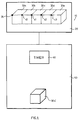
- Figure 1 illustrates the schematic for a system 10 for the dynamic display of three-dimensional (3D) images of a target.
- System 10 generally comprises a memory 20 to store a plurality of time-dependent 3D image data sets 30a-30e and at least one address pointer defining an independent address of a location in memory 20 of each of time-dependent 3D image data : sets 30a-30e.
- a memory 20 to store a plurality of time-dependent 3D image data sets 30a-30e and at least one address pointer defining an independent address of a location in memory 20 of each of time-dependent 3D image data : sets 30a-30e.
- the precise number of time-dependant 3D image data sets is not particularly restricted.
- the concordance between respective time-dependent 3D image data sets and addresses in memory 20 is as follows: 3D Image Data Set Address in Memory 20 30a 35 30b 40 30c 41 30d 42 30e 43 As illustrated, the individual 3D image data sets are preferably of substantially the same size and parameter.
- System 10 further comprises a display means 50 which utilizes the address pointer to retrieve a first time-dependent 3D image data set 30a from address 35 in memory 20 and display the first time-dependent 3D image (30a') for a selected period of time defined by timer 60.
- display means 50 retrieves another in the succession of time-dependent 3D image data sets 30b-30e from addresses 40-43, respectively, in memory 20 using the address pointer, and displays this second time-dependent 3D image, in place of the first time-dependent 3D image, for a selected period of time defined by timer 60.
- the duration of display of each of the successive time-dependent 3D images is not particularly limited and not all the images in a particular series need be displayed for the same length of time.
- the number of time-dependent 3D image data sets in a series is not limited.
- the example in shown in Figure 1 has a series of five time-dependent 3D image data sets. However, for the purposes of the present invention, only two different time-dependent 3D image data sets are required.
- the number of 3D image data sets generally will be less than 20 and possibly less than 10.
- the target is a muscle and the goal is to image it in flexure (total time interval of approximately 5 seconds)
- the number of 3D image data sets generally will be less than about 50 and possible less than 20.
- the system of the present invention is particularly useful in the field of medical imaging, where it can be used to display dynamic 3D images of moving tissue.
- the inventors have successfully used the system and method of this invention to produce real-time, dynamic 3D ultrasonographic images of the human heart, as will be described below.
- a Hewlett-Packard HP Sonos 2500TM ECO cardiology ultrasound machine was used in standard configuration to acquire a plurality of two-dimensional (2D) ultrasound images of a beating heart.
- the data was acquired using an axial scanning technique with a clockwise sweep of 180°.
- the data acquisition time was six minutes and the data was split into twenty two successive phases of the heart beat.
- 3D images of only eleven of these successive phases were constructed.
- Each 3D image comprised 91 2D frames of 224 x 216 pixels.
- Figures 2a-2k show the eleven successive 3D images generated.
- Figures 2a-2f show the systolic phase of the heart beat
- Figures 2g-2k show the diastolic phase of the heart beat.
- Each of the time-dependent 3D image data sets used to generate images 2a-2k are stored in a computer memory in series to give a four-dimensional (4D) data set, where time is the fourth dimension.
- An address pointer defines the location within the memory of the 4D data set and the location within the memory of the start of each of the individual 3D image data sets in the 4D data set.
- Each image can be retrieved from memory and displayed successively for a period of time determined by the user. Further, knowing the heart-rate of the subject, the entire series of 3D images can be displayed in succession in a continuous loop to give a real-time image of the beating heart.
- the present invention is not limited to the display of ultrasound images.
- this dynamic display technique may also be useful in the display of magnetic resonance or computed X-ray tomographic data.
- the 4D data set may not necessarily solely contain time-dependent 3D image data acquired using a single technique. For example, it may be desirable to show successive images of a target where each image is acquired using a different technique (i.e., combining magnetic resonance, computed X-ray tomographic and ultrasound images in a single 4D data set).
- the present method and system are directed toward ultrasonic 3D imaging.
- the present method and system are used in conjunction with ultrasonic 3D imaging it is preferred to incorporate the "fast" reconstruction technique described in copending United States patent application serial number 08/562,590 (which corresponds to International patent application publication number WO 97/20288), and United States provisional patent application serial number 60/041,345, filed March 21, 1997.
- the "fast" reconstruction technique allows manipulation of the displayed image via graphical input device (e.g., a mouse) to allow manipulations, with a single 3D image data set, such as rotation of the entire displayed 3D image about an arbitrary axis, translation of a selected plane of the displayed 3D image and rotation of a selected plane of the displayed 3D image about an arbitrary axis.
- graphical input device e.g., a mouse
- the address pointer may be used to identity in a particular 3D image data set the address corresponding to a desired manipulation.
- the address pointer can be used as described hereinabove with reference to Figure 1 to "refresh" the display image corresponding to the remaining 3D image data sets (recall it is preferred that the various 3D image data sets be of substantially the same size and parameter).
- the practical result of this is that the user simply manipulates one frame of the displayed image (i.e., reconstructed from one 3D image data set) and the remaining frames are displayed with a corresponding manipulation (i.e., reconstructed from each of the remaining 3D image data sets).
- the actual choice and design of an address pointer to switch between two modalities as described above is within the purview of a person skilled in the art.
- the system it is possible to modify the system to allow the user to select the following parameters: (i) total number of 3D image data sets; (ii) time interval of which each individual 3D image data set is collected; and (iii) aggregate time interval over which all 3D image data sets are collected. Further, it is possible, and preferred, to design the system to allow the use to freeze and, optionally, manipulate (as discussed above) a single frame of the dynamic image display.
Abstract
Description
- The present invention relates to the field of image data display. More specifically, the present invention relates to a system and method for the dynamic display of three-dimensional image data.
- Three-dimensional (3D) ultrasound imaging is a technique in which a set of spatially related two dimensional ultrasound slices (tomograms) of a target are collected and mathematically converted to create a virtual Cartesian ultrasound volume. This virtual ultrasound volume facilitates the visualization of non-acquired slices of the target and a variety of rendered surfaces and projections of the target otherwise unobtainable using two-dimensional (2D) ultrasound imaging.
- High fidelity 3D ultrasound requires, by definition, a data set in which the spacial relationship between the individual ultrasound slices is precisely known. High fidelity ultrasound is important for the accurate assessment of volumes and the appreciation of target geometry. The conventional method of choice for obtaining the precise spatial relationship between ultrasound slices is to actively constrain the position of each ultrasound slice. This is achieved by controlling the position of the ultrasound probe during generation of the slices by use of a motorized positioning device (mechanical scanning). Examples of 3D ultrasound imaging systems are described in detail in United States patents 5,454,371 (Fenster et al.) and 5,562,095 (Downey et al.),
- In the three-dimensional ultrasound imaging systems described in the afore-mentioned United States patents, when a succession of two-dimensional images have been captured and digitized, the two-dimensional images are stored as a stack to form an image data array. Before a three-dimensional image of the scanned volume can be created and viewed by a user, the image data array must be reconstructed to form a volumetric image array. This type of reconstruction, in which every pixel in every two-dimensional image slice is converted into an appropriate voxel in an image volume (i.e. volumetric image array) prior to display is known as "full volume" reconstruction. The generation of the complete volume array is somewhat inefficient, i.e. it is a time-consuming intermediate stage. Full volume reconstruction and display of a three-dimensional image using a conventional hardware platform can take upward of one minute and, therefore, has limited application in situations where immediate display of an acquired image is desirable.
- In an attempt to overcome the drawbacks associated with full volume reconstruction, the applicants developed a so-called "fast" reconstruction process which is described in copending United States patent application serial number 08/562,590 (which corresponds to International patent application publication number WO 97/20288), and United States provisional patent
application serial number 60/041,345, filed March 21, 1997. - In fast reconstruction, only the specific image data from the two-dimensional image slices that are actually required to view the user-selected image undergoes reconstruction. In other words, only the image data necessary to view the surface of user-selected image (i.e. as opposed to all of the data representing the entire volume of the target) is used for reconstruction. If, for example, the users wishes to view a particular image of the target volume, the computer uses associated calibration and acquisition parameters of the collected two-dimensional image slices to determine special "look-up" tables which speed up the determination of which data points from the two-dimensional image slices are required to be displayed on the monitor. Only the two-dimensional data points necessary to produce the desired image are reconstructed. There is no necessity to construct a full volume image array. Accordingly, this fast reconstruction is more emcient than conventional full volume reconstruction, i.e. it is less time-consuming (less than ½ second).
- Both "full volume" and "fast" reconstruction techniques are capable of generating and displaying high quality, single, three-dimensional images of a target, i.e., a temporal "snap-shot" of the target. These techniques are particularly useful in displaying images of non-dynamic, effectively stationary targets such as the breast, prostate or liver. However, the display of a single "snap-shot" is not optimally effective for imaging a dynamic target such as the heart or lungs.
- It is an object of the present invention to provide a system and method for dynamic image display which obviates and mitigates. at least one of the disadvantages of the prior art.
- The invention is set out in the claims.
- The terms "dynamic image display" and "dynamic display of three-dimensional images" are used interchangeably throughout this specification and are intended to include any method and/or system capable of displaying, in a time-dependent sequential manner, a three dimensional image of a target (e.g., organ, bodily structure, etc.) which is in a state of motion. The effect of this is to enable three dimensional visualization of changes in a target over time. Nonlimiting examples of applications of dynamic image display in which the present invention is useful include imaging of a beating heart, assessment the change of a physiological structure in the process of disease progression and the like.
- An embodiment of the present invention will now be described, by way of example only, with reference to the following figures, in which:
- Figure 1 is a schematic representation of the dynamic imaging method according to one embodiment of the present invention; and
- Figure 2a-2k illustrate time-dependent, sequential three-dimensional photographic images of a beating heart obtained using the present method and system.
-
- Figure 1 illustrates the schematic for a
system 10 for the dynamic display of three-dimensional (3D) images of a target.System 10 generally comprises amemory 20 to store a plurality of time-dependent 3Dimage data sets 30a-30e and at least one address pointer defining an independent address of a location inmemory 20 of each of time-dependent 3D image data :sets 30a-30e. Of course those of skill in the art will recognize that the precise number of time-dependant 3D image data sets is not particularly restricted. - In the illustrated embodiment, the concordance between respective time-dependent 3D image data sets and addresses in
memory 20 is as follows:3D Image Data Set Address in Memory 2030a 35 30b 40 30c 41 30d 42 30e 43 -
System 10 further comprises a display means 50 which utilizes the address pointer to retrieve a first time-dependent 3D image data set 30a fromaddress 35 inmemory 20 and display the first time-dependent 3D image (30a') for a selected period of time defined bytimer 60. - After the selected period of time, display means 50 retrieves another in the succession of time-dependent 3D
image data sets 30b-30e from addresses 40-43, respectively, inmemory 20 using the address pointer, and displays this second time-dependent 3D image, in place of the first time-dependent 3D image, for a selected period of time defined bytimer 60. - As will be apparent, the duration of display of each of the successive time-dependent 3D images is not particularly limited and not all the images in a particular series need be displayed for the same length of time. Further, the number of time-dependent 3D image data sets in a series is not limited. The example in shown in Figure 1 has a series of five time-dependent 3D image data sets. However, for the purposes of the present invention, only two different time-dependent 3D image data sets are required. Generally, there are three factors which should be taken into account in application of the present method and system: (i) the processor speed of the computer used to conduct image reconstruction; (ii) the duration of the total time interval over which the 3D image data sets are acquired; and (iii) the number of image data sets selected by the user. Thus, if the target is a beating heart and the goal is to image a single heartbeat (total time interval of approximately 1-2 seconds), given current computer processors, the number of 3D image data sets generally will be less than 20 and possibly less than 10. Alternatively, if the target is a muscle and the goal is to image it in flexure (total time interval of approximately 5 seconds), given current computer processors, the number of 3D image data sets generally will be less than about 50 and possible less than 20.
- The system of the present invention is particularly useful in the field of medical imaging, where it can be used to display dynamic 3D images of moving tissue. The inventors have successfully used the system and method of this invention to produce real-time, dynamic 3D ultrasonographic images of the human heart, as will be described below.
- A Hewlett-Packard HP Sonos 2500™ ECO cardiology ultrasound machine, was used in standard configuration to acquire a plurality of two-dimensional (2D) ultrasound images of a beating heart. The data was acquired using an axial scanning technique with a clockwise sweep of 180°. The data acquisition time was six minutes and the data was split into twenty two successive phases of the heart beat. For ease of data managenient, 3D images of only eleven of these successive phases were constructed. Each 3D image comprised 91 2D frames of 224 x 216 pixels. This type of cardiac data acquisition and 3D image reconstruction are both well known in the art and are described in more detail in the above-mentioned United States patents 5,454,371 (Fenster et al.) and 5,562,095 (Downey et al.).
- The eleven successive 3D images generated are shown in Figures 2a-2k. Figures 2a-2f show the systolic phase of the heart beat, while Figures 2g-2k show the diastolic phase of the heart beat.
- Each of the time-dependent 3D image data sets used to generate images 2a-2k are stored in a computer memory in series to give a four-dimensional (4D) data set, where time is the fourth dimension. An address pointer defines the location within the memory of the 4D data set and the location within the memory of the start of each of the individual 3D image data sets in the 4D data set. Each image can be retrieved from memory and displayed successively for a period of time determined by the user. Further, knowing the heart-rate of the subject, the entire series of 3D images can be displayed in succession in a continuous loop to give a real-time image of the beating heart.
- The present invention is not limited to the display of ultrasound images. For example, it is envisioned that this dynamic display technique may also be useful in the display of magnetic resonance or computed X-ray tomographic data. Further, it is envisioned that the 4D data set may not necessarily solely contain time-dependent 3D image data acquired using a single technique. For example, it may be desirable to show successive images of a target where each image is acquired using a different technique (i.e., combining magnetic resonance, computed X-ray tomographic and ultrasound images in a single 4D data set).
- Preferably, the present method and system are directed toward ultrasonic 3D imaging. When the present method and system are used in conjunction with ultrasonic 3D imaging it is preferred to incorporate the "fast" reconstruction technique described in copending United States patent application serial number 08/562,590 (which corresponds to International patent application publication number WO 97/20288), and United States provisional patent application
serial number 60/041,345, filed March 21, 1997. - When the "fast" reconstruction technique is used with the present method and system, it is preferred to design the address pointer such that it is sequentially incremented to allow it to switch between the modality described hereinabove with reference to Figure 1 and the modality in the '"fast"' reconstruction technique as described in the copending applications. The effect of this is as follows. The "fast" reconstruction technique, as described in the copending applications allows manipulation of the displayed image via graphical input device (e.g., a mouse) to allow manipulations, with a single 3D image data set, such as rotation of the entire displayed 3D image about an arbitrary axis, translation of a selected plane of the displayed 3D image and rotation of a selected plane of the displayed 3D image about an arbitrary axis. In the context of the present method and system, the address pointer may be used to identity in a particular 3D image data set the address corresponding to a desired manipulation. Once this is done, the address pointer can be used as described hereinabove with reference to Figure 1 to "refresh" the display image corresponding to the remaining 3D image data sets (recall it is preferred that the various 3D image data sets be of substantially the same size and parameter). The practical result of this is that the user simply manipulates one frame of the displayed image (i.e., reconstructed from one 3D image data set) and the remaining frames are displayed with a corresponding manipulation (i.e., reconstructed from each of the remaining 3D image data sets). The actual choice and design of an address pointer to switch between two modalities as described above is within the purview of a person skilled in the art.
- While this invention has been described with reference to an illustrative embodiment, this description is not intended to be construed in a limiting sense.
- For example, it is possible to modify the system to allow the user to select the following parameters: (i) total number of 3D image data sets; (ii) time interval of which each individual 3D image data set is collected; and (iii) aggregate time interval over which all 3D image data sets are collected. Further, it is possible, and preferred, to design the system to allow the use to freeze and, optionally, manipulate (as discussed above) a single frame of the dynamic image display.
Claims (2)
- A system (10) for the dynamic display of three-dimensional (3D) images of a target, characterised by:scanning means to scan a target volume to generate a succession of digitised two-dimensional (2D) images thereof;timing means (60) to determine the time interval between each of the succession of 2D images; andreconstruction means to generate a plurality of time-dependent 3D image data sets (30) of the target volume from the succession of digitized 2D images:memory means (20) to store the plurality of time-dependent 3D image data sets (30);an address pointer defining an independent address of a location in the memory means of each time-dependent 3D image data set (30); anddisplay means (50) utilising the address pointer successively to retrieve a time-dependent 3D image data set (30) from the memory means (20) and display a time-dependent 3D image corresponding to the time-dependent 3D image data set (30) for a selected period of time.
- A method for the dynamic display of three-dimension (3D) images of a target, the method characterised by the steps:scanning a target volume and generating a succession of digitized two-dimensional (2D) images thereof:determining the time interval between generations of the succession of 2D images; andgenerating a plurality of time-dependent 3D image data sets (30) of the target volume from the succession of digitized 2D images:(i) storing said plurality of time-dependent 3D image data sets (30) in a memory (30);(ii) defining an independent address of a location in the memory (20) for each time-dependent 3D images data set (30); and(iii) retrieving a time-dependent 3D image data set (30) from the memory (20);(iv) displaying the time-dependent 3D image corresponding to the time-dependent 3D image data set (30) for a selected period of time; and(v) repeating steps (iii) and (iv) for each remaining time-dependent 3D image data set (30).
Applications Claiming Priority (3)
| Application Number | Priority Date | Filing Date | Title |
|---|---|---|---|
| US5077997P | 1997-06-25 | 1997-06-25 | |
| US50779P | 1997-06-25 | ||
| PCT/CA1998/000625 WO1999000675A1 (en) | 1997-06-25 | 1998-06-25 | System and method for the dynamic display of three-dimensional image data |
Publications (2)
| Publication Number | Publication Date |
|---|---|
| EP0920639A1 EP0920639A1 (en) | 1999-06-09 |
| EP0920639B1 true EP0920639B1 (en) | 2005-12-14 |
Family
ID=21967377
Family Applications (1)
| Application Number | Title | Priority Date | Filing Date |
|---|---|---|---|
| EP98930595A Expired - Lifetime EP0920639B1 (en) | 1997-06-25 | 1998-06-25 | System and method for the dynamic display of three-dimensional image data |
Country Status (9)
| Country | Link |
|---|---|
| US (1) | US6342891B1 (en) |
| EP (1) | EP0920639B1 (en) |
| KR (1) | KR20000068309A (en) |
| AT (1) | ATE313088T1 (en) |
| AU (1) | AU8097798A (en) |
| CA (1) | CA2261227C (en) |
| DE (1) | DE69832774T2 (en) |
| IL (1) | IL128223A0 (en) |
| WO (1) | WO1999000675A1 (en) |
Families Citing this family (30)
| Publication number | Priority date | Publication date | Assignee | Title |
|---|---|---|---|---|
| US6765570B1 (en) * | 1998-07-21 | 2004-07-20 | Magic Earth, Inc. | System and method for analyzing and imaging three-dimensional volume data sets using a three-dimensional sampling probe |
| US6626834B2 (en) | 2001-01-25 | 2003-09-30 | Shane Dunne | Spiral scanner with electronic control |
| US20020164067A1 (en) * | 2001-05-02 | 2002-11-07 | Synapix | Nearest neighbor edge selection from feature tracking |
| US6971991B2 (en) * | 2002-03-08 | 2005-12-06 | Imperium, Inc. | Apparatus for multimodal plane wave ultrasound imaging |
| US7149566B2 (en) * | 2002-10-31 | 2006-12-12 | Manoa Medical, Inc. | Soft tissue orientation and imaging guide systems and methods |
| DE10308641A1 (en) * | 2003-02-27 | 2004-09-16 | Siemens Ag | Process for the preparation of existing time / phase dependent primary data sets of a computer tomograph from a moving object to a three-dimensional image series |
| CN1798988B (en) * | 2003-06-03 | 2010-11-24 | 皇家飞利浦电子股份有限公司 | Synchronizing a swiveling three-dimensional ultrasound display with an oscillating object |
| US8309428B2 (en) * | 2004-09-15 | 2012-11-13 | Sonetics Ultrasound, Inc. | Capacitive micromachined ultrasonic transducer |
| US7888709B2 (en) * | 2004-09-15 | 2011-02-15 | Sonetics Ultrasound, Inc. | Capacitive micromachined ultrasonic transducer and manufacturing method |
| US8658453B2 (en) * | 2004-09-15 | 2014-02-25 | Sonetics Ultrasound, Inc. | Capacitive micromachined ultrasonic transducer |
| US20070038088A1 (en) * | 2005-08-04 | 2007-02-15 | Rich Collin A | Medical imaging user interface and control scheme |
| US8425418B2 (en) * | 2006-05-18 | 2013-04-23 | Eigen, Llc | Method of ultrasonic imaging and biopsy of the prostate |
| US20080071292A1 (en) * | 2006-09-20 | 2008-03-20 | Rich Collin A | System and method for displaying the trajectory of an instrument and the position of a body within a volume |
| US20080071149A1 (en) * | 2006-09-20 | 2008-03-20 | Collin Rich | Method and system of representing a medical event |
| US8064664B2 (en) * | 2006-10-18 | 2011-11-22 | Eigen, Inc. | Alignment method for registering medical images |
| US7804989B2 (en) * | 2006-10-30 | 2010-09-28 | Eigen, Inc. | Object recognition system for medical imaging |
| US20080161687A1 (en) * | 2006-12-29 | 2008-07-03 | Suri Jasjit S | Repeat biopsy system |
| US8175350B2 (en) * | 2007-01-15 | 2012-05-08 | Eigen, Inc. | Method for tissue culture extraction |
| US20080186378A1 (en) * | 2007-02-06 | 2008-08-07 | Feimo Shen | Method and apparatus for guiding towards targets during motion |
| US7856130B2 (en) * | 2007-03-28 | 2010-12-21 | Eigen, Inc. | Object recognition system for medical imaging |
| US20090048515A1 (en) * | 2007-08-14 | 2009-02-19 | Suri Jasjit S | Biopsy planning system |
| US8571277B2 (en) * | 2007-10-18 | 2013-10-29 | Eigen, Llc | Image interpolation for medical imaging |
| US7942829B2 (en) * | 2007-11-06 | 2011-05-17 | Eigen, Inc. | Biopsy planning and display apparatus |
| US20090324041A1 (en) * | 2008-01-23 | 2009-12-31 | Eigen, Llc | Apparatus for real-time 3d biopsy |
| US20100001996A1 (en) * | 2008-02-28 | 2010-01-07 | Eigen, Llc | Apparatus for guiding towards targets during motion using gpu processing |
| US8315125B2 (en) * | 2009-03-18 | 2012-11-20 | Sonetics Ultrasound, Inc. | System and method for biasing CMUT elements |
| EP2248462B1 (en) * | 2009-05-06 | 2016-04-20 | Brainlab AG | Method for portraying image data of a patient body part |
| WO2017027789A1 (en) | 2015-08-12 | 2017-02-16 | Sonectics Ultrasound, Inc. | Method and system for measuring pressure using ultrasound |
| US10716544B2 (en) | 2015-10-08 | 2020-07-21 | Zmk Medical Technologies Inc. | System for 3D multi-parametric ultrasound imaging |
| EP3520083A4 (en) | 2016-09-30 | 2020-05-06 | University Hospitals Cleveland Medical Center | Apparatus and method for constructing a virtual 3d model from a 2d ultrasound video |
Family Cites Families (7)
| Publication number | Priority date | Publication date | Assignee | Title |
|---|---|---|---|---|
| US4791567A (en) * | 1986-09-15 | 1988-12-13 | General Electric Company | Three dimensional connectivity system employing an equivalence schema for determining connected substructures within a body |
| US5315512A (en) * | 1989-09-01 | 1994-05-24 | Montefiore Medical Center | Apparatus and method for generating image representations of a body utilizing an ultrasonic imaging subsystem and a three-dimensional digitizer subsystem |
| CA2110148C (en) | 1992-12-24 | 1999-10-05 | Aaron Fenster | Three-dimensional ultrasound imaging system |
| US5396890A (en) * | 1993-09-30 | 1995-03-14 | Siemens Medical Systems, Inc. | Three-dimensional scan converter for ultrasound imaging |
| US5454371A (en) | 1993-11-29 | 1995-10-03 | London Health Association | Method and system for constructing and displaying three-dimensional images |
| US5842473A (en) * | 1993-11-29 | 1998-12-01 | Life Imaging Systems | Three-dimensional imaging system |
| CA2181326C (en) * | 1995-07-17 | 2006-12-05 | Takashi Mochizuki | Ultrasound image processing apparatus and method for constructing a three-dimensional image from ultrasound beams in real time |
-
1998
- 1998-06-25 WO PCT/CA1998/000625 patent/WO1999000675A1/en active IP Right Grant
- 1998-06-25 KR KR1019997001461A patent/KR20000068309A/en not_active Application Discontinuation
- 1998-06-25 EP EP98930595A patent/EP0920639B1/en not_active Expired - Lifetime
- 1998-06-25 CA CA002261227A patent/CA2261227C/en not_active Expired - Lifetime
- 1998-06-25 AT AT98930595T patent/ATE313088T1/en not_active IP Right Cessation
- 1998-06-25 US US09/230,558 patent/US6342891B1/en not_active Expired - Lifetime
- 1998-06-25 DE DE69832774T patent/DE69832774T2/en not_active Expired - Lifetime
- 1998-06-25 IL IL12822398A patent/IL128223A0/en unknown
- 1998-06-25 AU AU80977/98A patent/AU8097798A/en not_active Abandoned
Also Published As
| Publication number | Publication date |
|---|---|
| US6342891B1 (en) | 2002-01-29 |
| DE69832774D1 (en) | 2006-01-19 |
| ATE313088T1 (en) | 2005-12-15 |
| AU8097798A (en) | 1999-01-19 |
| IL128223A0 (en) | 1999-11-30 |
| CA2261227C (en) | 2002-11-12 |
| KR20000068309A (en) | 2000-11-25 |
| WO1999000675A1 (en) | 1999-01-07 |
| EP0920639A1 (en) | 1999-06-09 |
| CA2261227A1 (en) | 1999-01-07 |
| DE69832774T2 (en) | 2006-08-10 |
Similar Documents
| Publication | Publication Date | Title |
|---|---|---|
| EP0920639B1 (en) | System and method for the dynamic display of three-dimensional image data | |
| US7386339B2 (en) | Medical imaging and navigation system | |
| Roelandt et al. | Ultrasonic dynamic three-dimensional visualization of the heart with a multiplane transesophageal imaging transducer | |
| JP5148094B2 (en) | Ultrasonic diagnostic apparatus, medical image processing apparatus, and program | |
| US5396890A (en) | Three-dimensional scan converter for ultrasound imaging | |
| US8494250B2 (en) | Animation for conveying spatial relationships in three-dimensional medical imaging | |
| Belohlavek et al. | Three-and four-dimensional cardiovascular ultrasound imaging: a new era for echocardiography | |
| Gee et al. | Engineering a freehand 3D ultrasound system | |
| US8317705B2 (en) | Method for generating a motion-corrected 3D image of a cyclically moving object | |
| US20070247454A1 (en) | 3D visualization with synchronous X-ray image display | |
| JP5481069B2 (en) | A reconstruction unit that reconstructs a detailed reproduction of at least part of an object | |
| JP4855926B2 (en) | Synchronizing swivel 3D ultrasonic display with vibration target | |
| Roelandt et al. | Precordial three‐dimensional echocardiography with a rotational imaging probe: Methods and initial clinical experience | |
| JP2003061956A (en) | Ultrasonic diagnostic apparatus, medical diagnosing apparatus and image processing method | |
| Fulton et al. | Dynamic three‐dimensional echocardiographic imaging of congenital heart defects in infants and children by computer‐controlled tomographic parallel slicing using a single integrated ultrasound instrument | |
| US7529431B2 (en) | Method and device for reconstructing and representing multidimensional objects from one-dimensional or two-dimensional image data | |
| Pini et al. | Echocardiographic three-dimensional visualization of the heart | |
| JP2001128982A (en) | Ultrasonic image diagnosing apparatus and image processor | |
| Salustri et al. | Three dimensional reconstruction of the heart with rotational acquisition: methods and clinical applications | |
| Bartz et al. | Virtual endoscopy for cardio vascular exploration | |
| Brekke et al. | Volume stitching in three-dimensional echocardiography: distortion analysis and extension to real time | |
| JP2012055765A (en) | Ultrasonic diagnostic device and program | |
| Roelandt | Three-dimensional echocardiography: new views from old windows. | |
| Nguyen et al. | Four-dimensional reconstruction of the left ventricle using a fast rotating classical phased array scan head: preliminary results | |
| FR2735966A1 (en) | ECHOGRAPHIC METHOD AND DEVICE FOR IMPLEMENTING THREE-DIMENSIONAL HEART ECHOGRAPHY |
Legal Events
| Date | Code | Title | Description |
|---|---|---|---|
| PUAI | Public reference made under article 153(3) epc to a published international application that has entered the european phase |
Free format text: ORIGINAL CODE: 0009012 |
|
| 17P | Request for examination filed |
Effective date: 19990204 |
|
| AK | Designated contracting states |
Kind code of ref document: A1 Designated state(s): AT BE CH CY DE DK ES FI FR GB GR IE IT LI LU MC NL PT SE |
|
| RAP1 | Party data changed (applicant data changed or rights of an application transferred) |
Owner name: LONDON HEALTH SCIENCES CENTRE |
|
| 17Q | First examination report despatched |
Effective date: 20040303 |
|
| GRAP | Despatch of communication of intention to grant a patent |
Free format text: ORIGINAL CODE: EPIDOSNIGR1 |
|
| GRAS | Grant fee paid |
Free format text: ORIGINAL CODE: EPIDOSNIGR3 |
|
| GRAA | (expected) grant |
Free format text: ORIGINAL CODE: 0009210 |
|
| AK | Designated contracting states |
Kind code of ref document: B1 Designated state(s): AT BE CH CY DE DK ES FI FR GB GR IE IT LI LU MC NL PT SE |
|
| PG25 | Lapsed in a contracting state [announced via postgrant information from national office to epo] |
Ref country code: LI Free format text: LAPSE BECAUSE OF FAILURE TO SUBMIT A TRANSLATION OF THE DESCRIPTION OR TO PAY THE FEE WITHIN THE PRESCRIBED TIME-LIMIT Effective date: 20051214 Ref country code: IT Free format text: LAPSE BECAUSE OF FAILURE TO SUBMIT A TRANSLATION OF THE DESCRIPTION OR TO PAY THE FEE WITHIN THE PRE;WARNING: LAPSES OF ITALIAN PATENTS WITH EFFECTIVE DATE BEFORE 2007 MAY HAVE OCCURRED AT ANY TIME BEFORE 2007. THE CORRECT EFFECTIVE DATE MAY BE DIFFERENT FROM THE ONE RECORDED.SCRIBED TIME-LIMIT Effective date: 20051214 Ref country code: FI Free format text: LAPSE BECAUSE OF FAILURE TO SUBMIT A TRANSLATION OF THE DESCRIPTION OR TO PAY THE FEE WITHIN THE PRESCRIBED TIME-LIMIT Effective date: 20051214 Ref country code: CH Free format text: LAPSE BECAUSE OF FAILURE TO SUBMIT A TRANSLATION OF THE DESCRIPTION OR TO PAY THE FEE WITHIN THE PRESCRIBED TIME-LIMIT Effective date: 20051214 Ref country code: BE Free format text: LAPSE BECAUSE OF FAILURE TO SUBMIT A TRANSLATION OF THE DESCRIPTION OR TO PAY THE FEE WITHIN THE PRESCRIBED TIME-LIMIT Effective date: 20051214 Ref country code: AT Free format text: LAPSE BECAUSE OF FAILURE TO SUBMIT A TRANSLATION OF THE DESCRIPTION OR TO PAY THE FEE WITHIN THE PRESCRIBED TIME-LIMIT Effective date: 20051214 |
|
| REG | Reference to a national code |
Ref country code: GB Ref legal event code: FG4D |
|
| REG | Reference to a national code |
Ref country code: CH Ref legal event code: EP |
|
| REG | Reference to a national code |
Ref country code: IE Ref legal event code: FG4D |
|
| REF | Corresponds to: |
Ref document number: 69832774 Country of ref document: DE Date of ref document: 20060119 Kind code of ref document: P |
|
| PG25 | Lapsed in a contracting state [announced via postgrant information from national office to epo] |
Ref country code: SE Free format text: LAPSE BECAUSE OF FAILURE TO SUBMIT A TRANSLATION OF THE DESCRIPTION OR TO PAY THE FEE WITHIN THE PRESCRIBED TIME-LIMIT Effective date: 20060314 Ref country code: GR Free format text: LAPSE BECAUSE OF FAILURE TO SUBMIT A TRANSLATION OF THE DESCRIPTION OR TO PAY THE FEE WITHIN THE PRESCRIBED TIME-LIMIT Effective date: 20060314 Ref country code: DK Free format text: LAPSE BECAUSE OF FAILURE TO SUBMIT A TRANSLATION OF THE DESCRIPTION OR TO PAY THE FEE WITHIN THE PRESCRIBED TIME-LIMIT Effective date: 20060314 |
|
| PG25 | Lapsed in a contracting state [announced via postgrant information from national office to epo] |
Ref country code: ES Free format text: LAPSE BECAUSE OF FAILURE TO SUBMIT A TRANSLATION OF THE DESCRIPTION OR TO PAY THE FEE WITHIN THE PRESCRIBED TIME-LIMIT Effective date: 20060325 |
|
| PG25 | Lapsed in a contracting state [announced via postgrant information from national office to epo] |
Ref country code: PT Free format text: LAPSE BECAUSE OF FAILURE TO SUBMIT A TRANSLATION OF THE DESCRIPTION OR TO PAY THE FEE WITHIN THE PRESCRIBED TIME-LIMIT Effective date: 20060515 |
|
| PG25 | Lapsed in a contracting state [announced via postgrant information from national office to epo] |
Ref country code: IE Free format text: LAPSE BECAUSE OF NON-PAYMENT OF DUE FEES Effective date: 20060626 |
|
| PG25 | Lapsed in a contracting state [announced via postgrant information from national office to epo] |
Ref country code: MC Free format text: LAPSE BECAUSE OF NON-PAYMENT OF DUE FEES Effective date: 20060630 |
|
| REG | Reference to a national code |
Ref country code: CH Ref legal event code: PL |
|
| ET | Fr: translation filed | ||
| PLBE | No opposition filed within time limit |
Free format text: ORIGINAL CODE: 0009261 |
|
| STAA | Information on the status of an ep patent application or granted ep patent |
Free format text: STATUS: NO OPPOSITION FILED WITHIN TIME LIMIT |
|
| 26N | No opposition filed |
Effective date: 20060915 |
|
| REG | Reference to a national code |
Ref country code: IE Ref legal event code: MM4A |
|
| PG25 | Lapsed in a contracting state [announced via postgrant information from national office to epo] |
Ref country code: LU Free format text: LAPSE BECAUSE OF NON-PAYMENT OF DUE FEES Effective date: 20060625 |
|
| PG25 | Lapsed in a contracting state [announced via postgrant information from national office to epo] |
Ref country code: CY Free format text: LAPSE BECAUSE OF FAILURE TO SUBMIT A TRANSLATION OF THE DESCRIPTION OR TO PAY THE FEE WITHIN THE PRESCRIBED TIME-LIMIT Effective date: 20051214 |
|
| REG | Reference to a national code |
Ref country code: FR Ref legal event code: PLFP Year of fee payment: 19 |
|
| REG | Reference to a national code |
Ref country code: FR Ref legal event code: PLFP Year of fee payment: 20 |
|
| PGFP | Annual fee paid to national office [announced via postgrant information from national office to epo] |
Ref country code: FR Payment date: 20170628 Year of fee payment: 20 Ref country code: GB Payment date: 20170628 Year of fee payment: 20 |
|
| PGFP | Annual fee paid to national office [announced via postgrant information from national office to epo] |
Ref country code: NL Payment date: 20170621 Year of fee payment: 20 |
|
| PGFP | Annual fee paid to national office [announced via postgrant information from national office to epo] |
Ref country code: DE Payment date: 20170627 Year of fee payment: 20 |
|
| REG | Reference to a national code |
Ref country code: DE Ref legal event code: R071 Ref document number: 69832774 Country of ref document: DE |
|
| REG | Reference to a national code |
Ref country code: NL Ref legal event code: MK Effective date: 20180624 |
|
| REG | Reference to a national code |
Ref country code: GB Ref legal event code: PE20 Expiry date: 20180624 |
|
| PG25 | Lapsed in a contracting state [announced via postgrant information from national office to epo] |
Ref country code: GB Free format text: LAPSE BECAUSE OF EXPIRATION OF PROTECTION Effective date: 20180624 |