EP0920295B1 - Massaging apparatus having two rollers and a suction chamber - Google Patents
Massaging apparatus having two rollers and a suction chamber Download PDFInfo
- Publication number
- EP0920295B1 EP0920295B1 EP97924191A EP97924191A EP0920295B1 EP 0920295 B1 EP0920295 B1 EP 0920295B1 EP 97924191 A EP97924191 A EP 97924191A EP 97924191 A EP97924191 A EP 97924191A EP 0920295 B1 EP0920295 B1 EP 0920295B1
- Authority
- EP
- European Patent Office
- Prior art keywords
- suction chamber
- roller
- rollers
- massaging apparatus
- skin
- Prior art date
- Legal status (The legal status is an assumption and is not a legal conclusion. Google has not performed a legal analysis and makes no representation as to the accuracy of the status listed.)
- Expired - Lifetime
Links
- 230000003746 surface roughness Effects 0.000 claims description 15
- 230000036316 preload Effects 0.000 claims description 6
- 238000007789 sealing Methods 0.000 description 9
- 238000010276 construction Methods 0.000 description 7
- 230000002349 favourable effect Effects 0.000 description 5
- 238000003379 elimination reaction Methods 0.000 description 4
- 239000000463 material Substances 0.000 description 4
- 238000005086 pumping Methods 0.000 description 2
- 239000007779 soft material Substances 0.000 description 2
- 230000005540 biological transmission Effects 0.000 description 1
- 230000015572 biosynthetic process Effects 0.000 description 1
- 239000000356 contaminant Substances 0.000 description 1
- 238000013016 damping Methods 0.000 description 1
- 230000001788 irregular Effects 0.000 description 1
- 239000002245 particle Substances 0.000 description 1
Images


Classifications
-
- A—HUMAN NECESSITIES
- A61—MEDICAL OR VETERINARY SCIENCE; HYGIENE
- A61H—PHYSICAL THERAPY APPARATUS, e.g. DEVICES FOR LOCATING OR STIMULATING REFLEX POINTS IN THE BODY; ARTIFICIAL RESPIRATION; MASSAGE; BATHING DEVICES FOR SPECIAL THERAPEUTIC OR HYGIENIC PURPOSES OR SPECIFIC PARTS OF THE BODY
- A61H7/00—Devices for suction-kneading massage; Devices for massaging the skin by rubbing or brushing not otherwise provided for
- A61H7/002—Devices for suction-kneading massage; Devices for massaging the skin by rubbing or brushing not otherwise provided for by rubbing or brushing
- A61H7/004—Devices for suction-kneading massage; Devices for massaging the skin by rubbing or brushing not otherwise provided for by rubbing or brushing power-driven, e.g. electrical
- A61H7/005—Devices for suction-kneading massage; Devices for massaging the skin by rubbing or brushing not otherwise provided for by rubbing or brushing power-driven, e.g. electrical hand-held
-
- A—HUMAN NECESSITIES
- A61—MEDICAL OR VETERINARY SCIENCE; HYGIENE
- A61H—PHYSICAL THERAPY APPARATUS, e.g. DEVICES FOR LOCATING OR STIMULATING REFLEX POINTS IN THE BODY; ARTIFICIAL RESPIRATION; MASSAGE; BATHING DEVICES FOR SPECIAL THERAPEUTIC OR HYGIENIC PURPOSES OR SPECIFIC PARTS OF THE BODY
- A61H15/00—Massage by means of rollers, balls, e.g. inflatable, chains, or roller chains
- A61H15/0078—Massage by means of rollers, balls, e.g. inflatable, chains, or roller chains power-driven
-
- A—HUMAN NECESSITIES
- A61—MEDICAL OR VETERINARY SCIENCE; HYGIENE
- A61H—PHYSICAL THERAPY APPARATUS, e.g. DEVICES FOR LOCATING OR STIMULATING REFLEX POINTS IN THE BODY; ARTIFICIAL RESPIRATION; MASSAGE; BATHING DEVICES FOR SPECIAL THERAPEUTIC OR HYGIENIC PURPOSES OR SPECIFIC PARTS OF THE BODY
- A61H15/00—Massage by means of rollers, balls, e.g. inflatable, chains, or roller chains
- A61H15/0078—Massage by means of rollers, balls, e.g. inflatable, chains, or roller chains power-driven
- A61H15/0085—Massage by means of rollers, balls, e.g. inflatable, chains, or roller chains power-driven hand-held
-
- A—HUMAN NECESSITIES
- A61—MEDICAL OR VETERINARY SCIENCE; HYGIENE
- A61H—PHYSICAL THERAPY APPARATUS, e.g. DEVICES FOR LOCATING OR STIMULATING REFLEX POINTS IN THE BODY; ARTIFICIAL RESPIRATION; MASSAGE; BATHING DEVICES FOR SPECIAL THERAPEUTIC OR HYGIENIC PURPOSES OR SPECIFIC PARTS OF THE BODY
- A61H7/00—Devices for suction-kneading massage; Devices for massaging the skin by rubbing or brushing not otherwise provided for
- A61H7/007—Kneading
- A61H7/008—Suction kneading
-
- A—HUMAN NECESSITIES
- A61—MEDICAL OR VETERINARY SCIENCE; HYGIENE
- A61H—PHYSICAL THERAPY APPARATUS, e.g. DEVICES FOR LOCATING OR STIMULATING REFLEX POINTS IN THE BODY; ARTIFICIAL RESPIRATION; MASSAGE; BATHING DEVICES FOR SPECIAL THERAPEUTIC OR HYGIENIC PURPOSES OR SPECIFIC PARTS OF THE BODY
- A61H15/00—Massage by means of rollers, balls, e.g. inflatable, chains, or roller chains
- A61H2015/0007—Massage by means of rollers, balls, e.g. inflatable, chains, or roller chains with balls or rollers rotating about their own axis
- A61H2015/0014—Massage by means of rollers, balls, e.g. inflatable, chains, or roller chains with balls or rollers rotating about their own axis cylinder-like, i.e. rollers
-
- A—HUMAN NECESSITIES
- A61—MEDICAL OR VETERINARY SCIENCE; HYGIENE
- A61H—PHYSICAL THERAPY APPARATUS, e.g. DEVICES FOR LOCATING OR STIMULATING REFLEX POINTS IN THE BODY; ARTIFICIAL RESPIRATION; MASSAGE; BATHING DEVICES FOR SPECIAL THERAPEUTIC OR HYGIENIC PURPOSES OR SPECIFIC PARTS OF THE BODY
- A61H15/00—Massage by means of rollers, balls, e.g. inflatable, chains, or roller chains
- A61H2015/0007—Massage by means of rollers, balls, e.g. inflatable, chains, or roller chains with balls or rollers rotating about their own axis
- A61H2015/0028—Massage by means of rollers, balls, e.g. inflatable, chains, or roller chains with balls or rollers rotating about their own axis disc-like, i.e. diameter substantially greater than width
- A61H2015/0035—Massage by means of rollers, balls, e.g. inflatable, chains, or roller chains with balls or rollers rotating about their own axis disc-like, i.e. diameter substantially greater than width multiple on the same axis
-
- A—HUMAN NECESSITIES
- A61—MEDICAL OR VETERINARY SCIENCE; HYGIENE
- A61H—PHYSICAL THERAPY APPARATUS, e.g. DEVICES FOR LOCATING OR STIMULATING REFLEX POINTS IN THE BODY; ARTIFICIAL RESPIRATION; MASSAGE; BATHING DEVICES FOR SPECIAL THERAPEUTIC OR HYGIENIC PURPOSES OR SPECIFIC PARTS OF THE BODY
- A61H9/00—Pneumatic or hydraulic massage
- A61H9/005—Pneumatic massage
Definitions
- the invention relates to a massaging apparatus comprising two rollers which are each rotatable about one of two mutually parallel spaced-apart roller spindles, which rollers can be placed onto the skin of a person with their circumferential surfaces and are rotationally drivable in a given direction of rotation when the massaging apparatus with its two rollers is moved over the skin of a person in a given operating direction which extends transversely to the roller spindles, and comprising a suction chamber in the area of the two rollers, which suction chamber encloses a suction space and comprises two transverse walls, which extend substantially perpendicularly to the roller spindles, and two longitudinal walls, which extend parallel to the roller spindles, are connected to the two transverse walls, and each have a free end adjacent the circumferential surface of a roller, which suction chamber is open in its area which faces a person's skin when the rollers are applied to the skin of a person and is connected to a pump for the transfer of air via an air-transfer connection
- Such a massaging apparatus of the type defined in the opening paragraph is known, for example, from the documents US 4,729,368 A and FR 2,573,100 A1.
- this known massaging apparatus the two rollers are disposed inside the suction chamber, in such a manner that both the two longitudinal walls and the two transverse walls of the suction chamber extend around the rollers. This results in a comparatively large contact area with which the suction chamber is in contact with a person's skin during operation of the massaging apparatus. Owing to this comparatively large contact area of the known apparatus it is comparatively difficult to achieve a proper sealing between the skin of a person and the suction chamber.
- the suction chamber has a comparatively large volume, as a result of which the evacuation of air from the suction chamber by means of a pump having a given pump capacity takes a comparatively long time in order to reach a certain desired vacuum and the massaging apparatus also becomes comparatively bulky, while it is further necessary that the roller spindles extend through the transverse walls, which gives rise to undesired leaks and, as a consequence, air leakage problems at the suction chamber.
- the known massaging apparatus further comprises two sealing flaps which are pivotally mounted at the location of a cover wall of the suction chamber, which also enclose the two rollers and during operation of this massaging apparatus engage with the circumferential surface portions of the two rollers which are remote from one another, in order to obtain a sealing inside the suction chamber.
- two sealing flaps since the degree of soiling of the rollers increases as the operating time increases, skin particles and other contaminants settling on the circumferential surfaces of the two rollers, causing an undesirable clearance between the sealing flaps and the circumferential surfaces of the two rollers, these two sealing flaps do not provide a proper sealing.
- another problem of the known massaging apparatus is that in operation of the massaging apparatus a person's skin may be caught or get pinched between the roller which is situated at the rear in the given operating direction and the adjacent longitudinal wall of the suction chamber.
- a massaging apparatus of the type defined in the opening paragraph is characterized in that at least one longitudinal wall of the suction chamber is disposed substantially between the two rollers, and the free end of a longitudinal wall disposed between the two rollers extends up to the circumferential surface of the roller adjacent this free end in that area of its circumferential surface which faces the other roller.
- the comparatively small contact area of the suction chamber with the skin has the advantage that comparatively small frictional forces occur between the walls of the suction chamber and a person's skin and the surface pressure between the walls of the suction chamber and a person's skin is comparatively low, as a result of which the massaging apparatus can be moved over a person's skin with comparatively small forces.
- a further advantage is that the suction chamber can have a comparatively small volume, as a result of which the evacuation of air from the suction chamber by means of a pump having a given pump capacity takes a comparatively short time in order to reach a certain desired vacuum and such a massaging apparatus can be of comparatively compact and simple construction. Moreover, it is thus possible to realize a massaging apparatus in accordance with the invention in which the suction chamber does not give rise to any air leakage problems at all or only to minor air leakage problems.
- a massaging apparatus in accordance with the invention at least that longitudinal side wall of the suction chamber, whose free end extends up to the circumferential surface of the roller which is situated at the front in the given operating direction, can be interposed between the two rollers.
- a dirt scraper is disposed adjacent that area of the circumferential surface of the rearward roller, viewed in the given operating direction, which is remote from forward roller, viewed in the given operating direction, which scraper is urged onto the circumferential surface of the rearward roller, viewed in the given operating direction, by means of at least one spring.
- suction chamber itself is absolutely sealed because the two transverse walls have no passages for leading through or for supporting the roller spindles, so that there are absolutely no air leakage problems caused by the bearing means of the rollers and a particularly rapid build-up of a vacuum in the perfectly sealed suction chamber is possible.
- the two transverse walls of the suction chamber are also disposed substantially between the two rollers. This is advantageous for a particularly small contact area of the suction chamber with a person's skin, and for a particularly compact construction of the suction chamber.
- the two longitudinal walls and the two transverse walls of the suction chamber form a dome-like suction space of substantially ellipsoidal shape without any corners inside the suction chamber. This is advantageous for a particularly gentle cooperation of the suction chamber with a skin portion drawn into the suction chamber and for a desired comparatively high mechanical stiffness of the suction chamber.
- the suction chamber forms part of a suction chamber support
- the bearing walls form parts of a bearing device
- the suction chamber support is fixedly connected to the bearing device. This is favorable for an advantageous construction of the apparatus.
- At least the forward roller has a circumferential surface with a surface roughness in a range between 0 ⁇ m and 2 ⁇ m.
- the two rollers can have a circumferential surface with a surface roughness ranging between 0 ⁇ m and 2 ⁇ m, but that the rearward roller, viewed in the given operating direction, can also have a higher surface roughness and can be made of a comparatively soft material.
- the two longitudinal walls and the two transverse walls of the suction chamber have a surface roughness in a range between 4 ⁇ m and 8 ⁇ m at the location of their bounding surfaces which can be brought into contact with the skin of a person.
- a minimal adhesion of the suction chamber walls to a person's skin and, consequently, a minimal friction between the suction chamber walls and a person's skin it has proved to be very favorable if there is such a surface roughness at the location of those bounding surfaces of the two longitudinal walls and the two transverse walls of the suction chamber which can be brought into contact with a person's skin.
- each of the two longitudinal walls extends up to the circumferential surface of a roller so as to form an air gap having a gap width of at the most 0.2 mm.
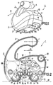
- Figure 1 is an oblique underneath view showing a massaging apparatus in accordance with a first embodiment of the invention, which comprises two rotationally drivable rollers and suction chamber having two longitudinal walls and two transverse walls, both the two longitudinal walls and the two transverse walls of the suction chamber being essentially disposed between the two rollers.
- Figure 2 shows a variant of the massaging apparatus of Figure 1 in a sectional view taken substantially across the center of the massaging apparatus, Figure 2 diagrammatically showing, in particular, the drive means for driving the two rotationally drivable rollers.
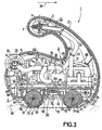
- Figure 3 shows a variant of the massaging apparatus of Figure 1 in a sectional view also taken substantially across the center of the massaging apparatus but inverted with respect to the sectional view of Figure 2, Figure 3 showing, in particular, the means for generating and influencing the partial vacuum in the suction chamber of the massaging apparatus.
- Figure 4 is an oblique underneath view of a suction chamber support for the suction chamber of the massaging apparatus as shown in Figures 1 and 3.
- Figure 5 is an oblique plan view of the suction chamber support shown in Figure 4 for the massaging apparatus as shown in Figures 1 and 3.
- Figure 6 is an oblique plan view of a bearing device included in the massaging apparatus in accordance with Figures 1 and 3, which bearing device serves for supporting the drive means for the rollers and for supporting the rollers themselves.
- Figure 7 shows a roller of a massaging apparatus in accordance with a second embodiment of the invention.
- Figure 8 shows a roller of a massaging apparatus in accordance with a third embodiment of the invention.
- Figure 9 is a highly diagrammatic sectional view of a massaging apparatus in accordance with a fourth embodiment of the invention.
- Figure 10 similarly to Figure 9, shows a highly diagrammatic sectional view of a massaging apparatus in accordance with a fifth embodiment of the invention.
- a massaging apparatus 1 embodying the invention will be described hereinafter with reference to Figures 1 to 6.
- the massaging apparatus 1 comprises a housing 2 having a grip portion 3, which at its free end changes into an end portion 4 of substantially ellipsoidal shape, which can be gripped by the fingers of a hand. At the location of its two side faces the end portion 4 has a push-button 5 and 6, respectively. Each of the two push-buttons 5 and 6 serves for opening an air valve of a vacuum-elimination valve device 7, which is shown in Figure 3.
- the vacuum-elimination valve device 7 will be described in more detail hereinafter.
- a rotary knob 10 which is rotatable about an axis 9, projects from a part 8 of the housing 2.
- the rotary knob 10 can be set from an off-position into an on-position and can then be set continuously from the on-position to various settings.
- a pump or pump motor of the massaging apparatus 1 is switched on and, in addition, a power supply circuit for the roller drive motor is activated.
- the roller drive motor is, in fact, not started until a given vacuum is reached in a suction chamber of the massaging apparatus 1, which is detected by means of an electropneumatic vacuum switch, which turns on the roller drive motor when the given desired vacuum in the suction chamber is detected.
- a controllable vacuum control valve is set to different vacuum values, so that it is possible to obtain different partial vacuums on the suction chamber of the massaging apparatus 1 by means of the controllable vacuum control valve.
- the massaging apparatus 1 further comprises a suction chamber support 11, which is shown separately in Figures 4 and 5.
- the suction chamber support 11 is fixedly connected to a bearing device 12 of the massaging apparatus 1.
- the bearing device 12 is shown separately in Figure 6.
- To connect the suction chamber support 11 to the bearing device 12 the suction chamber support 11 comprises four lugs 13, 14, 15 and 16, which each have a bore 17, 18, 19 and 20, respectively, near their respective free ends.
- To connect the suction chamber support 11 to the bearing device 12 the bearing device 12 comprises four mounting sleeves 21, 22, 23 and 24.
- the massaging apparatus 1 is movable over a part of a person's body, i.e. over the skin covering a part of a person's body, in a given operating direction indicated by an arrow 29 in Figures 1 to 6.
- the massaging apparatus 1 further comprises two rollers 30 and 31.
- Each of the two rollers 30 and 31 is rotatable about one of two spaced-apart mutually parallel roller spindles 32 and 33.
- the bearing device 12 For rotatably supporting the two rollers 30 and 31 the bearing device 12 has two bearing walls, of which only a bearing wall 34 is visible in Figure 6.
- the bearing wall 34 has two bearing bores 35 and 36, in which the roller spindles 32 and 33 are rotatably supported. With their circumferential surfaces 37 and 38 the two rollers 30 and 31 can be placed onto a person's skin 39, shown diagrammatically as a dotted line in Figure 3. During the movement of the massaging apparatus 1.
- the two rollers 30 and 31 can each be driven in a given direction of rotation.
- the two rollers 30 and 31 are each driven in the same direction of rotation, as indicated by means of two arrows 40 and 41 in Figures 2 and 3.
- the massaging apparatus 1 comprises a roller drive motor 42, which is secured to the bearing device 12.
- the roller drive motor has a nominal speed of approximately 8000 r.p.m.
- the roller drive motor 42 drives a first gear wheel 44 via its motor shaft 43, which gear wheel is in mesh with a second gear wheel 45.
- the second gear wheel 45 is rotatably supported on the bearing device 12 by means of a spindle 46.
- the second gear wheel 45 is coaxial with and rotationally locked to a third gear wheel 47.
- the third gear wheel 47 is in mesh with a fourth gear wheel 48, which is rotatably supported on the bearing device 12 by means of a spindle 49.
- the fourth gear wheel 48 is coaxial with and rotationally locked to a fifth gear wheel 50, which meshes with a sixth gear wheel 51 which is coaxial with and has the same diameter as the second gear wheel 45.
- the sixth gear wheel 51 is also rotatably supported on the bearing device 12 by means of the spindle 46.
- the sixth gear wheel 51 is coaxial with and rotationally locked to a seventh gear wheel 52.
- the seventh gear wheel 52 is in mesh with an eighth gear wheel 53, which is rotatably supported on the bearing device 12 by means of a spindle which is not shown in Figure 2.
- the eighth gear wheel 53 is in mesh with a ninth gear wheel 54, which is coaxial with and which is rotationally locked to the roller 30, and with a tenth gear wheel 55, which is coaxial with and which is rotationally locked to the roller 31.
- the forward roller 30, viewed in the given operating direction 29, is wholly made of a comparatively hard material, the circumferential surface 37 of the roller 30 advantageously having a surface roughness ranging between 0 ⁇ m and 2 ⁇ m.
- the interior of the rearward roller 31, viewed in the operating direction 29, is also made of a comparatively hard material but is surrounded by a shell of a comparatively soft material, the circumferential surface 38 of the rearward roller 31 having a higher surface roughness than the circumferential surface 37 of the forward roller 30.
- the surface roughness of the circumferential surface 38 of the rearward roller 31 may range approximately between 3 ⁇ m and 6 ⁇ m.
- the massaging apparatus 1 further has a suction chamber 56 in the area of the two rollers 30 and 31, which chamber bounds a suction space.
- the suction chamber 56 has two transverse walls 57 and 58, which extend substantially perpendicularly to the roller spindles 32 and 33, two longitudinal walls 59 and 60, which extend parallel to the roller spindles 32 and 33 and which are connected to the two transverse walls 57 and 58, and a cover wall 61, which is connected both to the two transverse walls 57 and 58 and to the two longitudinal walls 59 and 60.
- the suction chamber 56 is open in its area which faces a person's skin 39 when the rollers 30 and 31 are applied to the skin 39 of a person.
- Each of the two longitudinal walls 59 and 60 has a free end 62, 63 adjacent the circumferential surface 37, 38 of a roller 30, 31, which free end - viewed in the direction of the roller spindles 32 and 33 - has a shape which is substantially straight only in its center portion and which extends parallel to the two roller spindles 32 and 33 but which is curved in its two end portions.
- the suction chamber 56 - as is apparent particularly from Figure 5 - has two juxtaposed connection tubes 64 and 65.
- the suction chamber 56 is connected to a pump 67 via a first air-transfer line 66, shown in Figure 3, for the transfer of air, which pump is disposed in the massaging apparatus 1 and is secured to the bearing device 12.
- the pump 67 comprises a pump motor 68 to drive an air-pumping device of the pump 67.
- the first air-transfer line 66 between the first connection tube 64 and the pump 67 comprises a first hose section 69 fitted onto the first connection tube 64, a first T-piece 70, which is connected to the first hose section 69, and a second hose section 71, which is connected to the first T-piece 70 and to a pump connection, not shown in Figure 3.
- the pump 67 can generate a partial vacuum in the suction chamber 56 in order to draw a skin fold 72 into the suction chamber 56, shown diagrammatically as a dotted line in Figure 3.
- the afore-mentioned vacuum-elimination valve device 7 is connected to the first T-piece 70 via a third hose section 73.
- the vacuum-elimination valve device 7 comprises two air valves, of which an air valve 74 is shown in Figure 3.
- the air valve 74 can be opened by actuation of the push-button 6.
- the air valve 74, or the second air valve which can be opened by actuation of the push-button 5 and which is not visible in Figure 3 is open the partial vacuum previously formed in the suction chamber 56 by means of the pump 67 is eliminated via the third hose section 73, the first T-piece 70, the first hose section 69 and the connection pipe 64.
- This is advantageous in view of an easy and painless withdrawal of the suction chamber 56 , i.e. of the massaging apparatus 1, from the skin 39 of a person.
- a second air-transfer line 75 is connected to the second connection tube 65 of the suction chamber 56.
- the second air-transfer line 75 comprises a fourth hose section 76 fitted onto the second connection tube 65 of the suction chamber 56, a second T-piece 77, which is connected to the fourth hose section 76, and a fifth hose section 78, which is connected to the second T-piece 77 and to a vacuum control valve 79, by means of which a desired vacuum in the suction chamber 56 can be selected by suitably turning the rotary knob 10.
- a vacuum control valve 79 As long as a vacuum, which can be generated in the suction chamber 56 of the massaging apparatus 1 by the pumping action of the pump 67, is not yet reached the vacuum control valve 79 is in its closed condition. However, when a desired vacuum in the suction chamber 56 is exceeded the vacuum control valve 79 opens automatically, allowing leakage air to flow into the suction chamber 56 via the air-transfer line 75 until the desired partial vacuum is established in the suction chamber 56.
- an electropneumatic vacuum switch 81 is connected to the second T-piece 77 via a sixth hose section 80.
- the vacuum switch 81 performs an electrical switching function.
- the vacuum switch 81 performs an electrical switching function, for example, at a given vacuum having a value of approximately 80 millibar.
- the vacuum switch 81 forms part of a motor supply device, not shown, for the roller drive motor 42, the vacuum switch 81 enabling the roller drive motor 42 to be turned on when a given vacuum in the suction chamber 56 is reached.
- each free end 62 or 63 of a longitudinal wall 59 or 60 interposed between the two rollers 30 and 31 then extends up to the respective circumferential surface 37 or 38 of the roller 30 or 31 adjacent this free end 62 or 63 in its circumferential surface area which faces the other roller 31 or 30.
- each of the two longitudinal walls 59 and 60 extends up to the respective circumferential surface 37 or 38 of a roller 30 or 31 so as to form an air gap, not shown, having a gap width of approximately 0.1 mm.
- the gap width of the air gap between the free ends 62 and 63 of the longitudinal walls 59 and 60 and the circumferential surfaces 37 and 38 of the two rollers 30 and 31 can alternatively have a smaller value of, for example, 0.05 mm but also a larger value of, for example, 0.15 mm to 0.2 mm.
- the two longitudinal walls 59 and 60, the two transverse walls 57 and 58, and the cover wall 61 of the suction chamber 56 bound a dome-like suction space of substantially ellipsoidal shape without any corners inside the suction chamber 56, which is favorable for a comfortable and careful massage of a skin fold 72.
- the two longitudinal walls 59 and 60 and the two transverse walls 57 and 58 of the suction chamber 56 have a surface roughness of approximately 6 ⁇ m at the location of their bounding surfaces which can be brought into contact with the skin 39 of a person.
- these bounding surfaces can alternatively have a surface roughness of 4 ⁇ m, 5 ⁇ m, 7 ⁇ m or 8 ⁇ m.
- Such a surface roughness has proved to be advantageous for a low adhesion of the walls 57, 58, 59 and 60 of the suction chamber 56 to the skin 39 of a person and, consequently, for a minimal friction between the walls 57, 58, 59 and 60 of the suction chamber 56 to the skin 39 of a person.
- a filter 83 is arranged in a passage leading to the two connection pipes 64 and 65, as can be seen in Figures 2 and 3.
- the suction chamber 56 has three mounting sleeves 84, 85 and 86 which are integral with the suction chamber 56 and into which the fixing bolts passed through the bearing device 12 can be screwed, thus providing an additional fixed connection between the suction chamber support 11 and the bearing device 12.
- the massaging apparatus 1 comprises a dirt scraper 87 adjacent that area of the circumferential surface of the rearward roller 31 in the given operating direction 29, which is remote from forward roller 30 in the given operating direction 29, which scraper is urged onto the circumferential surface 38 of the rearward roller 31 in the given operating direction 29 by means of a spring 88 in the form of a leg spring.
- This dirt scraper 87 ensures that in the area of the rearward roller 31 in the given operating direction 29 no ingress of dirt into the massaging apparatus 1 is possible and that the skin 39 of a person cannot get trapped in the area of the rearward roller 31 in the given operating direction 29 because this is precluded by the dirt scraper 87, which is urged onto the circumferential surface 38 of the roller 31.
- the suction chamber can have a very small volume, as a result of which the evacuation of air from the suction chamber by means of a pump of given pump capacity incorporated in the massaging apparatus can be effected in a comparatively short time in order to reach a certain desired vacuum. Owing to the small volume of the suction chamber the massaging apparatus can be comparatively compact at least at the location of the suction chamber.
- a special advantage of the massaging apparatus described above is that the suction chamber itself is absolutely sealed so that there are absolutely no air leakage problems at the location of the suction chamber walls and, as a consequence, a particularly rapid build-up of a vacuum in the perfectly sealed suction chamber is possible. Furthermore, it is to be noted that owing to the dome-like rounded shape of the suction chamber in its interior a particularly gentle cooperation of the suction chamber with the skin fold which has been drawn into suction chamber is guaranteed and an advantageously high mechanical stiffness of the suction chamber is achieved.
- the rotatable mounting of the two rollers of the massaging apparatus in the bearing walls of the bearing device which is fixedly connected to the suction chamber and the suction chamber support has the advantage that by means of the bearing walls of the bearing device the two rollers are rotatably supported in a fixed relationship with the suction chamber, i.e. the walls of the suction chamber, which is advantageous in view of a constant relative position of the rollers with respect to their adjacent longitudinal walls and, consequently, in view of a constant air gap between each roller and its adjacent longitudinal wall.
- the selected surface roughnesses of the circumferential surfaces of the two rollers in the massaging apparatus described above ensures a particularly favorable cooperation of the rollers with a person's skin. In view of a minimal friction between the longitudinal walls of the suction chamber and a person's skin it has also proved to be favorable that the longitudinal walls with their free ends for the greater part recede into the interior of the apparatus.
- Fig. 7 shows only a detail of a massaging apparatus in accordance with a second embodiment of the invention.
- This detail concerns the forward roller 30, viewed in the given operating direction 29 of the massaging apparatus 1, which roller is rotationally drivable about the roller spindle 32 in the direction indicated by the arrow 40.
- the longitudinal wall 59 of the suction chamber 56 which is shown only partly, is disposed behind the roller 30, viewed in the given operating direction 29.
- the roller 30 has circumferential grooves 89. Furthermore, in this massaging apparatus 1 the longitudinal wall 59, which follows the roller 30 viewed in the given operating direction 29, has tooth-like wall extensions 90, each wall extension 90 engaging in a groove 89 of the roller 30. In the present case, the wall extensions 90 are formed as comparatively short projections of the longitudinal wall 59.
- FIG 8 in the same way as Figure 7, shows a detail of a massaging apparatus in accordance with a third embodiment of the invention.
- This Figure also shows the forward roller 30, viewed in the given operating direction 29, and the longitudinal wall 59 of the suction chamber 56 of this massaging apparatus 1, which wall is disposed adjacent this roller 30.
- the roller 30 of this massaging apparatus 1 also has grooves 89, in which the wall extensions 90 of the longitudinal wall 59 engage.
- the wall extensions 90 are formed by comparatively long arcuate projections of the longitudinal wall 59, the arcuate shape of these projections having a radius substantially equal to the radius of the roller 30.
- FIG. 9 is a highly diagrammatically view showing a massaging apparatus in accordance with a fourth embodiment of the invention.
- this massaging apparatus only one longitudinal wall of the suction chamber 56 is interposed between the two rollers 30 and 31, which are rotationally drivable in the directions indicated by the arrows 40 and 41 in accordance with the given operating direction 29.
- the roller spindle 32 of the forward roller 30 in the given operating direction 29 is rotatably supported in the two transverse walls of the suction chamber 56 in the massaging apparatus 1 shown in Figure 9.
- a transverse wall 91 is shown in Figure 9.
- the roller spindle 33 of the rearward roller 31 in the given operating direction 29 is rotatably supported in two transverse wall portions of the housing 2 in the massaging apparatus 1 shown in Figure 9. Of these two transverse wall portions of the housing 2 only a transverse wall portion 92 is shown in Figure 9.
- suction chamber 56 also forms part of a suction chamber support 11.
- suction chamber support 11 is directly secured to the housing 2 by means of diagrammatically shown screwthread connections.
- the massaging apparatus 1 shown in Figure 9 only one longitudinal wall of the suction chamber 56 is interposed between the two rollers 30 and 31 in the massaging apparatus 1 shown in Figure 9.
- This is the longitudinal wall 95 of the suction chamber 56, whose free end 96 extends up to the circumferential surface 38 of the rearward roller 31 in the given operating direction 29.
- the massaging apparatus 1 shown in Figure 9 also has a comparatively small contact area for the suction chamber 56 on the skin 39 of a person and the suction chamber 56 has a comparatively small volume.
- FIG 10 in the same way as Figure 9, shows a massaging apparatus 1 in accordance with a fifth embodiment of the invention.
- the massaging apparatus shown Figure 10 is of a substantially mirror-inverted construction, as is apparent from Figure 10.
- the roller spindle 32 of the forward roller 30 in the given operating direction 29 is rotatably supported in two transverse wall portions of the housing 2. Of these two transverse wall portions of the housing 2 only a transverse wall portion 99 is shown in Figure 10.
- the roller spindle 33 of the rearward roller 31 in the given operating direction 29 is rotatably supported in the two transverse walls of the suction chamber 56. Of the two transverse walls of the suction chamber 56 only a transverse wall 100 is shown in Figure 10.
- the suction chamber 56 In the massaging apparatus 1 shown in Figure 10 only one longitudinal wall of the suction chamber 56 is disposed between the two rollers 30, i.e. the longitudinal wall 101 of the suction chamber 56, whose free end 102 extends up to the circumferential surface 37 of the forward roller 30 in the given operating direction 29.
- the second longitudinal wall 103 of the suction chamber 56 which is partly covered by a longitudinal wall portion 104 of the housing 2 and whose free end 105 extends up to the circumferential surface 38 of the roller 31 in the given operating direction 29, follows the roller 31, viewed in the given operating direction 29, and is consequently not disposed between the two rollers 30 and 31.
- the construction of the suction chamber 56 is such that of the two longitudinal walls 101 and 103 of the suction chamber 56 the respective free ends 102 and 105 of both longitudinal walls 101 and 103 are urged under pre-load against the circumferential surfaces 37 and 38 of the rollers 30 and 31 adjacent the respective free ends 102 and 105.
- This pre-load is obtained by an appropriate design of the longitudinal walls 101 and 103, which has been chosen in such a manner that during assembly of the massaging apparatus 1 shown in Figure 10 the two longitudinal walls 101 and 102 are loaded by the rollers 30 and 31 at the location of their free ends 102 and 105, which gives rise to the pre-load in the two longitudinal walls 101 and 103.
- a pre-load to keep the free end of a longitudinal wall urged against the circumferential surface of the roller adjacent this free end need not necessarily be obtained by the design of the relevant longitudinal wall but can also be achieved by the provision of a separate spring, such as a blade spring, which can be integrated at least partly in a longitudinal wall.
- the massaging apparatus 1 shown in Figure 10 also has the advantages of a comparatively small contact area of the walls of the suction chamber 56 on the skin 39 of a person and a comparatively small volume of the suction chamber 56.
- the invention is not limited to the embodiments described above.
- the measures in accordance with the invention can also be applied advantageously to massaging apparatuses of different constructions.
- a massaging apparatus comprising two rollers which are rotationally drivable by means of a roller drive motor it is alternatively possible to provide independent drive transmissions which are at least partly independent from one another between the roller drive motor and each of the two rollers, and to drive the forward roller, viewed in the given operating direction of a massaging apparatus, with a higher speed than the rearward roller, viewed in the given operating direction of a massaging apparatus, as a result of which it is achieved that the forward roller, which is driven with a higher speed, tends to feed more skin or tissue into the suction cone than is moved out of the suction chamber by the rearward roller, which is driven more slowly, thereby assisting the two rollers in the formation of a skin fold which is drawn into the suction chamber of such a massaging apparatus.
- a motor drive for the two rollers can be dispensed completely in a massaging apparatus in accordance with the invention and the rollers can be driven by the mere friction between a person's skin and the rollers, but in this may lead to an irregular drive of the two rollers and even to a brief standstill of a roller.
Landscapes
- Health & Medical Sciences (AREA)
- Epidemiology (AREA)
- Pain & Pain Management (AREA)
- Physical Education & Sports Medicine (AREA)
- Rehabilitation Therapy (AREA)
- Life Sciences & Earth Sciences (AREA)
- Animal Behavior & Ethology (AREA)
- General Health & Medical Sciences (AREA)
- Public Health (AREA)
- Veterinary Medicine (AREA)
- Dermatology (AREA)
- Massaging Devices (AREA)
Abstract
Description
Claims (14)
- A massaging apparatus (1) comprising two rollers (30,31) which are each rotatable about one of two mutually parallel spaced-apart roller spindles (32,33), which rollers (30,31) can be placed onto the skin of a person with their circumferential surfaces (37,38) and are rotationally drivable in a given direction of rotation (40,41) when the massaging apparatus (1) with its two rollers (30,31) is moved over the skin of a person in a given operating direction (29) which extends transversely to the roller spindles (32,33), and comprising a suction chamber (56) in the area of the two rollers (30,31), which suction chamber (56) encloses a suction space and comprises two transverse walls (57,58), which extend substantially perpendicularly to the roller spindles (32,33), and two longirudinal walls (59,60; 95,97; 101,103), which extend parallel to the roller spindles (32,33), are connected to the two transverse walls (57,58), and each have a free end (62,63) adjacent the circumferential surface (37,38) of a roller (30,31), which suction chamber (56) is open in its area which faces a person's skin when the rollers (30,31) are applied to the skin of a person and is connected to a pump (67) for the transfer of air via an air-transfer connection (66), by means of which pump (67) - with the rollers (30,31) applied to the skin of a person - a partial vacuum can be generated in the suction chamber (56) in order to form a skin fold (72) which is drawn into the suction chamber (56), characterized in that at least one longitudinal wall (59,60; 95; 101) of the suction chamber (56) is disposed substantially between the two rollers (30,31), and the free end (62,63; 96; 102) of a longitudinal wall (59,60; 95; 101) disposed between the two rollers (30,31) extends up to the circumferential surface (37,38) of the roller (30,31) adjacent this free end (62,63; 96; 102) in that area of its circumferential surface (37,38) which faces the other roller (31,30).
- A massaging apparatus (1) as claimed in Claim 1, characterized in that at least that longitudinal wall (60; 95) of the suction chamber (56), whose free end (63; 96) extends up to the circumferential surface (38) of the rearward roller (31) viewed in the given operating direction (29), is disposed substantially between the two rollers (30,31).
- A massaging apparatus (1) as claimed in Claim 2, characterized in that a dirt scraper (87) is disposed adjacent that area of the circumferential surface of the rearward roller (31), viewed in the given operating direction (29), which is remote from forward roller (30), viewed in the given operating direction (29), which scraper (87) is urged onto the circumferential surface (38) of the rearward roller (31), viewed in the given operating direction (29), by means of at least one spring (88).
- A massaging apparatus (1) as claimed in any one of the Claims 1 to 3, characterized in that the two longitudinal walls (59,60) of the suction chamber (56) are disposed substantially between the two rollers (30,31).
- A massaging apparatus (1) as claimed in Claim 4, charactized in that, in addition, the two transverse walls (57,58) of the suction chamber (56) are also disposed substantially between the two rollers (30,31).
- A massaging apparatus (1) as claimed in Claim 5, characterized in that the two longitudinal walls (59,60) and the two transverse walls (57,58) of the suction chamber (56) form a dome-like suction space of substantially ellipsoidal shape without any corners inside the suction chamber (56).
- A massaging apparatus (1) as claimed in any one of the Claims 4 to 6, characterized in that bearing walls (34), which extend transversely to the roller spindles (32,33) and which project laterally from the suction chamber (56), are fixedly connected to the suction chamber (56) disposed between the two rollers (30,31), and the two rollers (30,31) are rotatably supported by means of the bearing walls (34).
- A massaging apparatus (1) as claimed in Claim 7, characterized in that the suction chamber (56) forms part of a suction chamber support (11), the bearing walls (34) form parts of a bearing device (12), and the suction chamber support (11) is fixedly connected to the bearing device (12).
- A massaging apparatus (1) as claimed in any one of the Claims 1 to 8, characterized in that of the two rollers (30,31) at least the forward roller (30), viewed in the given operating direction (29), has a circumferential surface (37) with a surface roughness in a range between 0 µm and 2 µm.
- A massaging apparatus (1) as claimed in any one of the Claims 1 to 9, characterized in that the two longitudinal walls (59,60), and the two transverse walls (57,58) of the suction chamber (56) have a surface roughness in a range between 4 µm and 8 µm at the location of their bounding surfaces which can be brought into contact with the skin (39) of a person.
- A massaging apparatus (1) as claimed in any one of the Claims 1 to 10, characterized in that at least for the greater part the free, end (62,63; 98,96; 102,105) of each of the two longitudinal walls (59,60; 97,95; 101,103) recedes towards the apparatus interior with respect to a tangential plane (82) common to the two rollers in their areas which face the skin of a person - with the rollers applied to the skin of a person.
- A massaging apparatus (1) as claimed in any one of the Claims 1 to 11, characterized in that the free (62,63; 98,96) end of each of the two longitudinal walls (59, 60; 97,95) extends up to the circumferential surface (37,38) of a roller (30,31) so as to form an air gap having a gap width of at the most 0.2 mm.
- A massaging apparatus (1) as claimed in Claim 12, characterized in that the free end (102,105) of at least one longitudinal wall (101,103) of the two longitudinal walls (101,103) of the suction chamber is urged against the circumferential surface (37,38) of the roller (30,31) adjacent this free end (102,105) under pre-load.
- A massaging apparatus (1) as claimed in any one of the Claims 1 to 13, characterized in that a roller (30) which, viewed in the given operating direction (29), is followed by longitudinal wall (59) of the suction chamber (56) has circumferential grooves (89), and the longitudinal wall (59) following this roller (30) has tooth-like wall extensions (90) which each engage in a groove (89) in this roller (30).
Priority Applications (1)
| Application Number | Priority Date | Filing Date | Title |
|---|---|---|---|
| EP97924191A EP0920295B1 (en) | 1996-07-15 | 1997-06-13 | Massaging apparatus having two rollers and a suction chamber |
Applications Claiming Priority (4)
| Application Number | Priority Date | Filing Date | Title |
|---|---|---|---|
| EP96890121 | 1996-07-15 | ||
| EP96890121 | 1996-07-15 | ||
| EP97924191A EP0920295B1 (en) | 1996-07-15 | 1997-06-13 | Massaging apparatus having two rollers and a suction chamber |
| PCT/IB1997/000698 WO1998002124A1 (en) | 1996-07-15 | 1997-06-13 | Massaging apparatus having two rollers and a suction chamber |
Publications (2)
| Publication Number | Publication Date |
|---|---|
| EP0920295A1 EP0920295A1 (en) | 1999-06-09 |
| EP0920295B1 true EP0920295B1 (en) | 2002-03-13 |
Family
ID=8226202
Family Applications (1)
| Application Number | Title | Priority Date | Filing Date |
|---|---|---|---|
| EP97924191A Expired - Lifetime EP0920295B1 (en) | 1996-07-15 | 1997-06-13 | Massaging apparatus having two rollers and a suction chamber |
Country Status (7)
| Country | Link |
|---|---|
| US (1) | US6017320A (en) |
| EP (1) | EP0920295B1 (en) |
| JP (1) | JP4040100B2 (en) |
| CN (1) | CN1165270C (en) |
| AT (1) | ATE214260T1 (en) |
| DE (2) | DE920295T1 (en) |
| WO (1) | WO1998002124A1 (en) |
Cited By (1)
| Publication number | Priority date | Publication date | Assignee | Title |
|---|---|---|---|---|
| RU2506069C2 (en) * | 2012-03-05 | 2014-02-10 | Федеральное государственное бюджетное учреждение науки Государственный научный центр Российской Федерации Институт медико-биологических проблем Российской академии наук | Walk simulator with feedback system |
Families Citing this family (47)
| Publication number | Priority date | Publication date | Assignee | Title |
|---|---|---|---|---|
| FR2768051B1 (en) * | 1997-09-11 | 1999-10-08 | Lpg Systems | MASSAGE APPARATUS EXERCISING SUCTION AND MOBILIZATION OF SKIN TISSUE |
| FR2772263B1 (en) * | 1997-12-16 | 2000-02-11 | Seb Sa | SKIN SUCTION AND MASSAGE APPARATUS |
| FR2782002B1 (en) * | 1998-08-06 | 2000-10-27 | Jean Frajdenrajch | PERFECTED MASSAGE DEVICE INTENDED TO BE APPLIED TO A PERSON'S SKIN |
| DE69923949T2 (en) | 1998-10-16 | 2006-04-06 | Koninklijke Philips Electronics N.V. | MASSAGE DEVICE WITH SUCTION CHAMBER AND TWO ROLL BODIES |
| CN1188098C (en) | 1998-10-16 | 2005-02-09 | 皇家菲利浦电子有限公司 | Massaging apparatus having a suction chamber and two rollers |
| CN1181801C (en) | 1998-10-16 | 2004-12-29 | 皇家菲利浦电子有限公司 | A massager with handle device |
| US6319211B1 (en) * | 1998-10-26 | 2001-11-20 | Matsushita Electric Works, Ltd. | Facial aesthetic treatment apparatus |
| ATE397435T1 (en) | 1998-11-18 | 2008-06-15 | Nugyn Inc | DEVICES FOR TREATING THE CLITORIS |
| US6964643B2 (en) * | 1998-11-18 | 2005-11-15 | Nugyn, Inc. | Devices and methods for treatment of incontinence |
| US6511445B2 (en) * | 1998-11-24 | 2003-01-28 | Tactica International, Inc. | Cellulite massage system with gel dispenser |
| WO2000048548A1 (en) * | 1999-02-18 | 2000-08-24 | Koninklijke Philips Electronics N.V. | Vacuum massaging apparatus having a pump and having noise reduction means in the pump area |
| USD426641S (en) * | 1999-09-02 | 2000-06-13 | Lee Smith | Body shaping device |
| EP1261307A1 (en) * | 1999-12-15 | 2002-12-04 | Tensor Technologies, LLC | Massage device |
| FR2809952B1 (en) * | 2000-06-09 | 2004-04-23 | Louis Paul Guitay | MASSAGE APPARATUS COMPRISING AT LEAST ONE ROTATOR POSITIVELY ROTATED |
| US20020002346A1 (en) * | 2000-06-29 | 2002-01-03 | Horst Patricia J. | Apparatus and method of massaging back and alleviating back pain using suction cup |
| DE60211128T2 (en) | 2001-02-27 | 2007-01-11 | Koninklijke Philips Electronics N.V. | MASSAGE DEVICE WITH A HOUSING LOOKING ON THE SKIN OF A USER |
| US20040260210A1 (en) * | 2003-06-23 | 2004-12-23 | Engii (2001) Ltd. | System and method for face and body treatment |
| US20040260209A1 (en) * | 2003-06-23 | 2004-12-23 | Engli (2001) Ltd. | System and method for face and body treatment |
| US20050148910A1 (en) | 2003-12-24 | 2005-07-07 | Gregory Skover | Apparatus having a skin-contactable element containing an agent |
| JP2005296042A (en) * | 2004-04-06 | 2005-10-27 | Japan Esthetique Kyokai:Kk | Fat removing apparatus |
| US7585284B2 (en) * | 2004-05-04 | 2009-09-08 | Sam Zhadanov | Body rubbing device |
| ATE481958T1 (en) * | 2006-01-20 | 2010-10-15 | Eleme Medical Inc | MECHANICAL MASSAGER |
| ITFI20060047A1 (en) * | 2006-02-23 | 2007-08-24 | Maurizio Busoni | EQUIPMENT FOR THE TREATMENT OF INESTETISMS DUE TO THE CUTANEOUS STRIES AND METHOD FOR THE COSMETIC TREATMENT OF THESE INESTETISMS |
| FR2902318B1 (en) * | 2006-06-19 | 2009-01-30 | Louisin Res And Dev Ltd | DEVICE FOR THE TREATMENT, IN PARTICULAR OF MASSAGE, OF THE CONNECTIVE TISSUE OF THE SKIN |
| WO2008060494A2 (en) | 2006-11-09 | 2008-05-22 | Lumenis, Inc. | Apparatus and method for treating tissue |
| USD610692S1 (en) * | 2009-06-10 | 2010-02-23 | David Heilman | Personal massager |
| JP5186441B2 (en) * | 2009-06-29 | 2013-04-17 | パナソニック株式会社 | Beauty machine |
| USD626657S1 (en) * | 2009-08-18 | 2010-11-02 | Kessel Marketing & Vertriebs Gmbh | Manual erection system |
| CN101904794B (en) * | 2010-08-25 | 2012-07-25 | 浙江金恒数控科技股份有限公司 | Kneading and message device |
| USD696786S1 (en) * | 2012-07-27 | 2013-12-31 | The Global DR Group LLC | Hand-held massager |
| FR3012035B1 (en) * | 2013-10-17 | 2016-01-01 | Seb Sa | MASSAGE APPARATUS WITH MASSAGE HEAD EQUIPPED WITH A PALLET ROLLER AND A ROLL WITH A SMOOTH-TYPE SURFACE |
| EP3160414B1 (en) * | 2014-06-30 | 2019-10-30 | Koninklijke Philips N.V. | A bodycare device |
| JP6175636B2 (en) * | 2015-08-31 | 2017-08-09 | 株式会社ユニッシュ | Beauty machine |
| US10959907B2 (en) | 2018-09-15 | 2021-03-30 | Uccellini LLC | Stimulation device having a pressure field stimulator and a roller massager |
| US11007113B2 (en) | 2018-09-15 | 2021-05-18 | Uccellini LLC | Pressure field stimulator having a cup integrated with a sheath |
| CN108309740B (en) * | 2018-02-12 | 2019-10-18 | 西北工业大学 | A mobile back massage robot |
| US11229574B2 (en) | 2018-09-15 | 2022-01-25 | Uccellini LLC | Massager device with expansion function |
| EP3644936A4 (en) * | 2018-09-15 | 2021-01-27 | Uccellini LLC | Personal massager having an arm adaptable in shape |
| US10940076B2 (en) | 2018-09-15 | 2021-03-09 | Uccellini LLC | Personal massager |
| US11517495B2 (en) | 2018-09-15 | 2022-12-06 | Uccellini Inc. | Pressure field stimulation device having adaptable arm |
| US11504296B2 (en) | 2018-09-15 | 2022-11-22 | Uccellini, Inc. | Personal massager |
| CN109199827B (en) * | 2018-11-08 | 2023-10-20 | 范亚硕 | Portable abdominal push and massage care device |
| CN109646881B (en) * | 2019-01-14 | 2020-05-15 | 佳木斯大学 | A kind of auxiliary rehabilitation device for fracture patients |
| FR3097431B1 (en) * | 2019-06-20 | 2022-09-23 | Seb Sa | IMPROVED MASSAGE HEAD FOR MASSAGE APPLIANCE AND MASSAGE APPLIANCE EQUIPPED WITH SUCH A HEAD |
| JP1702209S (en) * | 2021-04-08 | 2021-12-13 | ||
| CN117224374A (en) * | 2023-10-12 | 2023-12-15 | 深圳市御美高标科技有限公司 | A multifunctional beauty instrument |
| CN120114315B (en) * | 2025-02-26 | 2025-12-12 | 中国科学院半导体研究所 | Automatic ridge pinching equipment imitating human hand and control method thereof |
Family Cites Families (15)
| Publication number | Priority date | Publication date | Assignee | Title |
|---|---|---|---|---|
| US1268963A (en) * | 1917-10-12 | 1918-06-11 | Halla F Gray | Carpet-cleaning machine. |
| US1514949A (en) * | 1921-03-24 | 1924-11-11 | Bell Schoenleber Mfg Co Inc | Sweeper |
| US1663167A (en) * | 1927-06-15 | 1928-03-20 | Koester Walter | Massage apparatus |
| CH135999A (en) * | 1928-11-09 | 1929-10-31 | Wilhelm Mellwig Joseph | Device for processing floors by means of motor-driven processing rollers arranged on two axes. |
| US1840796A (en) * | 1930-05-20 | 1932-01-12 | John D Schweers | Massage device |
| US2574601A (en) * | 1949-11-28 | 1951-11-13 | Hugo R Swanson | Therapeutic massager |
| GB926968A (en) * | 1960-10-10 | 1963-05-22 | Ozonair Engineering Company Lt | Improvements in or relating to pneumatic suction nozzles |
| US3297024A (en) * | 1963-11-04 | 1967-01-10 | Fred M Robinson | Massaging machine having suction means and oppositely rotating rollers |
| FR2057514A5 (en) * | 1969-08-25 | 1971-05-21 | Lapasset Andre | |
| FR2579100B1 (en) * | 1985-03-19 | 1989-03-03 | Guitay Louis Paul | HUMAN BODY MASSAGE APPARATUS |
| FR2589726B1 (en) * | 1985-11-14 | 1987-12-04 | Guitay Louis | HUMAN BODY MASSAGE APPARATUS |
| FR2612395B1 (en) * | 1987-03-17 | 1992-01-17 | Guitay Louis Paul | HUMAN BODY MASSAGE APPARATUS |
| US5127128A (en) * | 1989-07-27 | 1992-07-07 | Goldstar Co., Ltd. | Cleaner head |
| US5086539A (en) * | 1990-10-31 | 1992-02-11 | Racine Industries, Inc. | Carpet cleaning machine with pattern-oriented vacuum nozzle |
| US5665053A (en) * | 1996-09-27 | 1997-09-09 | Jacobs; Robert A. | Apparatus for performing endermology with ultrasound |
-
1997
- 1997-06-13 JP JP50578998A patent/JP4040100B2/en not_active Expired - Fee Related
- 1997-06-13 AT AT97924191T patent/ATE214260T1/en not_active IP Right Cessation
- 1997-06-13 WO PCT/IB1997/000698 patent/WO1998002124A1/en not_active Ceased
- 1997-06-13 EP EP97924191A patent/EP0920295B1/en not_active Expired - Lifetime
- 1997-06-13 DE DE0920295T patent/DE920295T1/en active Pending
- 1997-06-13 CN CNB971912572A patent/CN1165270C/en not_active Expired - Lifetime
- 1997-06-13 DE DE69711056T patent/DE69711056T2/en not_active Expired - Lifetime
- 1997-07-11 US US08/891,607 patent/US6017320A/en not_active Expired - Lifetime
Cited By (1)
| Publication number | Priority date | Publication date | Assignee | Title |
|---|---|---|---|---|
| RU2506069C2 (en) * | 2012-03-05 | 2014-02-10 | Федеральное государственное бюджетное учреждение науки Государственный научный центр Российской Федерации Институт медико-биологических проблем Российской академии наук | Walk simulator with feedback system |
Also Published As
| Publication number | Publication date |
|---|---|
| CN1204956A (en) | 1999-01-13 |
| DE920295T1 (en) | 2002-02-21 |
| ATE214260T1 (en) | 2002-03-15 |
| CN1165270C (en) | 2004-09-08 |
| DE69711056T2 (en) | 2002-11-07 |
| DE69711056D1 (en) | 2002-04-18 |
| WO1998002124A1 (en) | 1998-01-22 |
| US6017320A (en) | 2000-01-25 |
| JP4040100B2 (en) | 2008-01-30 |
| EP0920295A1 (en) | 1999-06-09 |
| JPH11512961A (en) | 1999-11-09 |
Similar Documents
| Publication | Publication Date | Title |
|---|---|---|
| US6017320A (en) | Massaging apparatus having two rollers and a suction chamber | |
| US5891064A (en) | Massaging apparatus having two rollers and suction chamber | |
| US6370798B1 (en) | Clothes dryer with vacuum assistance | |
| JPH0675560B2 (en) | Vacuum cleaner | |
| EP1554947A1 (en) | Skin care device | |
| MXPA05001610A (en) | Surface treating appliance. | |
| GB2320421A (en) | Air-driven power brush for vacuum cleaner | |
| JPH10192204A (en) | Brush head assembly of vacuum cleaner | |
| JP2774073B2 (en) | Vacuum cleaner suction port | |
| JP2002537021A (en) | Vacuum massage device having a pump and having noise reduction means in the area of the pump | |
| KR100778690B1 (en) | Upright type vacuum cleaner angle adjuster | |
| WO2000023031A1 (en) | Massaging apparatus having a suction chamber and at least one roller | |
| JPH11244204A (en) | Suction tool for floor | |
| JP2918155B2 (en) | Remote control vacuum cleaner | |
| JP2006158783A (en) | Electric vacuum cleaner | |
| KR970011912B1 (en) | Device for controlling the suction power of vacuum cleaner without the power source | |
| JP3597367B2 (en) | Suction port body and vacuum cleaner provided with the suction port body | |
| JP3421802B2 (en) | Air suction adjustment device in vacuum cleaner | |
| KR950003347Y1 (en) | Brake device for wheel of vacuum cleaner | |
| JP2005296042A (en) | Fat removing apparatus | |
| KR0148951B1 (en) | Flexible neck structure of vacuum cleaner | |
| KR100396767B1 (en) | Suction pump of vacuum cleanet | |
| KR100222645B1 (en) | Extention pipe of vacuum cleaner | |
| JP2008023016A (en) | Upright vacuum cleaner | |
| KR100345273B1 (en) | Rotary brush for vacuum cleaner |
Legal Events
| Date | Code | Title | Description |
|---|---|---|---|
| PUAI | Public reference made under article 153(3) epc to a published international application that has entered the european phase |
Free format text: ORIGINAL CODE: 0009012 |
|
| 17P | Request for examination filed |
Effective date: 19980722 |
|
| AK | Designated contracting states |
Kind code of ref document: A1 Designated state(s): AT DE FR GB |
|
| TCAT | At: translation of patent claims filed | ||
| EL | Fr: translation of claims filed | ||
| 17Q | First examination report despatched |
Effective date: 20010709 |
|
| GRAG | Despatch of communication of intention to grant |
Free format text: ORIGINAL CODE: EPIDOS AGRA |
|
| GRAG | Despatch of communication of intention to grant |
Free format text: ORIGINAL CODE: EPIDOS AGRA |
|
| GRAH | Despatch of communication of intention to grant a patent |
Free format text: ORIGINAL CODE: EPIDOS IGRA |
|
| REG | Reference to a national code |
Ref country code: GB Ref legal event code: IF02 |
|
| GRAG | Despatch of communication of intention to grant |
Free format text: ORIGINAL CODE: EPIDOS AGRA |
|
| GRAH | Despatch of communication of intention to grant a patent |
Free format text: ORIGINAL CODE: EPIDOS IGRA |
|
| GRAA | (expected) grant |
Free format text: ORIGINAL CODE: 0009210 |
|
| DET | De: translation of patent claims | ||
| AK | Designated contracting states |
Kind code of ref document: B1 Designated state(s): AT DE FR GB |
|
| REF | Corresponds to: |
Ref document number: 214260 Country of ref document: AT Date of ref document: 20020315 Kind code of ref document: T |
|
| REF | Corresponds to: |
Ref document number: 69711056 Country of ref document: DE Date of ref document: 20020418 |
|
| ET | Fr: translation filed | ||
| PLBE | No opposition filed within time limit |
Free format text: ORIGINAL CODE: 0009261 |
|
| STAA | Information on the status of an ep patent application or granted ep patent |
Free format text: STATUS: NO OPPOSITION FILED WITHIN TIME LIMIT |
|
| 26N | No opposition filed |
Effective date: 20021216 |
|
| PGFP | Annual fee paid to national office [announced via postgrant information from national office to epo] |
Ref country code: AT Payment date: 20090625 Year of fee payment: 13 |
|
| PG25 | Lapsed in a contracting state [announced via postgrant information from national office to epo] |
Ref country code: AT Free format text: LAPSE BECAUSE OF NON-PAYMENT OF DUE FEES Effective date: 20100613 |
|
| REG | Reference to a national code |
Ref country code: DE Ref legal event code: R082 Ref document number: 69711056 Country of ref document: DE Representative=s name: GOESSMANN, KLEMENS, DIPL.-ING., DE |
|
| REG | Reference to a national code |
Ref country code: DE Ref legal event code: R082 Ref document number: 69711056 Country of ref document: DE Representative=s name: GOESSMANN, KLEMENS, DIPL.-ING., DE Effective date: 20140331 Ref country code: DE Ref legal event code: R081 Ref document number: 69711056 Country of ref document: DE Owner name: KONINKLIJKE PHILIPS N.V., NL Free format text: FORMER OWNER: KONINKLIJKE PHILIPS ELECTRONICS N.V., EINDHOVEN, NL Effective date: 20140331 |
|
| REG | Reference to a national code |
Ref country code: FR Ref legal event code: CD Owner name: KONINKLIJKE PHILIPS N.V., NL Effective date: 20141126 Ref country code: FR Ref legal event code: CA Effective date: 20141126 |
|
| REG | Reference to a national code |
Ref country code: FR Ref legal event code: PLFP Year of fee payment: 20 |
|
| PGFP | Annual fee paid to national office [announced via postgrant information from national office to epo] |
Ref country code: GB Payment date: 20160630 Year of fee payment: 20 |
|
| PGFP | Annual fee paid to national office [announced via postgrant information from national office to epo] |
Ref country code: FR Payment date: 20160630 Year of fee payment: 20 |
|
| PGFP | Annual fee paid to national office [announced via postgrant information from national office to epo] |
Ref country code: DE Payment date: 20160831 Year of fee payment: 20 |
|
| REG | Reference to a national code |
Ref country code: DE Ref legal event code: R071 Ref document number: 69711056 Country of ref document: DE |
|
| REG | Reference to a national code |
Ref country code: GB Ref legal event code: PE20 Expiry date: 20170612 |
|
| PG25 | Lapsed in a contracting state [announced via postgrant information from national office to epo] |
Ref country code: GB Free format text: LAPSE BECAUSE OF EXPIRATION OF PROTECTION Effective date: 20170612 |