BACKGROUND OF THE INVENTION
The present invention relates to a method and apparatus
for multiplex transmission suitable for use in the Synchronous
Digital Hierarchy. The preset patent application pertains to
Japanese Published Unexamined Patent Application No. Hei
9-321729 and corresponding U.S. Patent Application Serial
No. 08/863675, the disclosure of which is hereby incorporated
by reference.
In today's digital transmission networks, the technology
of synchronization has been advanced to such a degree that a
communication network is synchronized with faster transmission
apparatuses employing optical transmission. For functions and
configurations of the digital transmission networks and
transmission apparatuses, worldwide standards have been
established such that a transmission apparatus and/or a
communication network may be introduced in conformity to the
standards to provide high quality transmission anywhere in the
world. Examples of specific standards may include the standard
(established in 1988) on a transmission system referred to as
"SDH" (Synchronous Digital Hierarchy) defined in
Recommendation G.707 and so on by International
Telecommunication Union-Telecommunication Sector ("ITU-T"),
and the standard (established in 1991) on a transmission system
referred to as "SONET" (Synchronous Optical Network) defined
in Standard T1.105 American National Standard Institute
("ANSI"), both of which define the configuration of optical
synchronous communication systems and functions of
transmission apparatuses.
The SDH and SONET standards are intended for the process
(for transmission or multiplexing/demultiplexing) of
synchronous multiplex signals (frames) which are the main
signal section of digitized and multiplex main signals called
"payload" added by signals called "transport overhead" used
for the operation, administration, maintenance and
provisioning (OAM&P) of the transmission equipment and
communication network. The transport overhead has a pointer,
which is used for the stuff control of phase accommodation and
frequency justification. Based on this scheme, it becomes
possible to provide a transmission system which is less
susceptible to transmission delay and is superior in the OAM&P
ability.
Transmission techniques based on this kind of transport
overhead are disclosed in Japanese Published Unexamined Patent
Application No. Hei 4-79628 and U.S. Patent No.5, 682, 257 for
example. In regard to the transmission scheme with the
intention of enhancing the latitude of SDH or SONET-based
network organization, there is known suggestive article
T1X1.5/96-085 addressed to ANSI for example.
The synchronous digital transmission network of this type
uses the bidirectional line switched ring (BLSR) which is the
ring-wise connection of OC-12 transmission paths for example.
The transmission paths have their protection switching made
conformable to the protocols of the Bidirectional Line Switched
Ring stated in the ANSI Recommendation T1.105.01 and the MS
Shared Protection Rings stated in the ITU-T Recommension G.841.
Specifically, the protection switching operation is carried
out among plural multiplex units which constitute the ring
network by use of the K1 byte and K2 byte, which are called
"automatic protection switching (APS) bytes", placed in the
transport overhead of synchronous-multiplex signals.
For grading up a transmission network, OC-12 paths in
ring-wise connection are replaced partially with OC-192 paths
which have a larger transmission capability. In this case,
transaction of the above-mentioned K1 and K2 bytes needed for
the protection switching operation is shut off at the multiplex
transmission unit located between the OC-12 path and OC-192
path, causing the OC-12 ring network to fail to retain its
protection switching operation. The reason is because the APS
bytes sent over the OC-12 path is terminated by the multiplex
unit connected at one end of the OC-192 path, and is not
propagated to the counterpart of another end, as stated in the
SONET and SDH standards. The APS bytes sent over the OC-192
path is used solely for the protection switching operation of
the OC-192 path. Therefore, it is not easy in general to
accomplish a network in which a section of the BLSR
(Bidirectional Line Switched Ring) network of OC-M is multiplex
to a network of OC-N (N is greater than M) having a larger
transmission capability.
The sole feasible manner for this accomplishment is to
send by through-transport the OAM&P information inclusive of
the APS bytes, which comes in from the OC-12 path, through the
OC-192 section. For example, it is assumed that multiplex
units A, F, G, D and E form a BLSR network of A ↔ F ↔ G
↔ D ↔ E ↔ A, of which the F ↔ G is a high-speed OC-192
path section and the rest are low-speed OC-12 path sections.
If a fault arises in the OC-12 path section E ↔ A, the
multiplex units A and E detect the fault and transact the APS
bytes which are coded in accordance with the BLSR protocol over
the paths A ↔ F ↔ G ↔ D ↔ E by transporting through
the OC-192 path section E ↔ G, thereby implementing the
protection switching. This scheme allows a OC-12 ring network,
even though it includes a OC-192 path, to retain the protection
switching operation, and enables the network organization at
a relatively high latitude.
However, the above-mentioned scheme can possibly fail to
implement the protection switching in need in case a fault
arises at a specific position of transmission paths. For
example, if a fault arises in the transmission path section
A ↔ F of the above-mentioned BLSR network, it is expected
according to the above-mentioned scheme that the OAM&P
information inclusive of the APS bytes from the OC-12 path
should be sent by through-transport through the OC-192 path
section and protection switching should be carried out.
However, it does not take place this time. This fault differs
from the above-mentioned case in that the faulty OC-12 path
has its one end connected with the multiplex unit F which is
connected to the OC-192 path. In such a case, even if the fault
of the upstream path is indicated to the downstream multiplex
unit D, BLSR switching (span switching or ring switching of
BLSR) does not take place in the multiplex unit D. The following
will explain the reason in detail.
In the SONET and SDH standards, it is stated that in
response to the detection by a multiplex unit of a fault of
transmission path such as the loss of signal, loss of frame,
or AIS-L (or MS-AIS in the SDH), AIS-P (or AU-AIS in the SDH)
which is the alarm for the STS path layer is transported to
the downstream unit. The AIS-P is to set a "1"s bit string to
the STS synchronous payload envelope and STS pointers (H1, H2
and H3 bytes). The OC-12 receiver of the unit F detects the
loss of signal and transports the AIS-P to the downstream unit
G. On receiving the AIS-P, the unit G further transports the
AIS-P to the downstream unit D. However, in the SONET and SDH
standards, the reception of AIS-P does not cause the BLSR
switching of OC-12 paths.
Accordingly, any alarm information, either for transport
overhead or payload, which causes the BLSR switching will not
be transported depending on the faulty section, and therefore
the BLSR switching of OC-12 paths which is needed for the unit
D for example will not be implemented. Consequently, the OC-12
network is left unrecoverable. This signifies that the path
which runs between the multiplex units A and D by way of the
units F and G, for example, is left in the defective state,
causing the OC-12 network to be inoperative.
A conceivable preventive manner against this impropriety
is the multiplex units F and G installing the protection
switching, i.e., BLSR switching, function for the OC-12 network,
so that the units F and G are treated as nodes of the OC-12
network equally to the A and other multiplex units.
Accordingly, the units F and G implement the BLSR switching
of OC-12 paths in accordance with the APS bytes of the
transmission frame of OC-12. At that time, the APS bytes for
the BLSR switching of the OC-12 paths is sent through the OC-192
path section between the units F and G by being inserted into
the undefined area of the line overhead of the OC-192
transmission frame. The BLSR switching is implemented by the
unit G instead of F since a partial band of the OC-192 path
cannot be operated for the OC-12 BLSR. This manner, however,
necessitates the BLSR switching function for a maximum of 16
low-speed OC-12 paths, and it is not realistic from the
viewpoints of system scale and cost.
The foregoing is an example of a fault occurring on the
OC-12 path of the direction from unit A to unit F, and it is
also relevant to a fault occurring on the OC-12 path of the
direction from unit D to unit G. Moreover, in the event of a
fault which is irrecoverable by the protection switching, e.g.,
simultaneous switching failure of the working line and
protection line, on the OC-192 path between the units F and
G, which is the case of demand of BLSR switching by the units
A and D, switching does not take place by the same reason as
described above.
A problem involved in the art stated above is that at the
occurrence of a fault on a OC-M transmission path which is
immediately preceding the multiplexing to a high-speed OC-N
signal (N is greater than M), or at the occurrence of a fault
which is irrecoverable by the protection switching on the OC-12
path, the protection switching which is inherently the case
of demand by the OC-M network is not implemented and moreover
the system is left in a state in which the OC-M signal is treated
to be normal.
SUMMARY OF THE INVENTION
Accordingly, it is an object of the present invention to
provide a method and apparatus for multiplex transmission which
are capable of implementing the protection switching of
transmission paths reliably.
The above objective is achieved in such a manner that at
the occurrence of a fault on a low-speed transmission path which
is immediately preceding the multiplexing to a high-speed
transmission path, an alarm is sent by through-transport to
the high-speed path by being inserted into a certain location
of the transport overhead of the multiplex signal of the
high-speed path. The location of insertion of the transport
overhead is a predetermined undefined area, and the alarm is
such a signal having low-order 3 bits of "111".
At the occurrence of a fault on a high-speed transmission
path which is immediately preceding the demultiplexing to a
low-speed transmission path, an alarm is transported to the
low-speed path by being inserted into a certain location of
the transport overhead of the multiplex signal of the low-speed
path. At the occurrence of a fault on a high-speed
transmission path of a multiplex transmission unit which is
located between two high-speed paths, an alarm is sent by
through-transport to the high-speed path by being inserted into
a certain location of the transport overhead of the multiplex
signal of the high-speed path.
The arrangement in this manner ensures the alteration of
the configuration of transmission network and the operation
of protection switching of transmission paths. The inventive
method and apparatus are capable of accomplishing a multiplex
transmission equipment and multiplex transmission network
having the invariable ability of protection switching
operation even if the transmission network is altered.
It should be noted that throughout this patent
specification, the term "low-speed path" signifies a
transmission path which carries low-speed signals, and the term
"high-speed path" signifies a transmission path which carries
high-speed signals. The low-speed signal is a multiplex signal
having a lower bit rate and the high-speed signal is a multiplex
signal having a higher bit rate in a sense of relativity.
BRIEF DESCRIPTION OF THE DRAWINGS
Preferred embodiments of the present invention will now
be described in conjunction with the accompanying drawings,
in which:
DESCRIPTION OF THE PREFERRED EMBODIMENTS
Preferred embodiments of the present invention will be
explained with reference to the drawings. Although the
following embodiments deal with the SONET-based transmission,
the invention is equally applicable to the SDH-based
transmission.
The inventive method and apparatus are designed to
terminate the transport overhead of the transmission frame at
each node and transport the specified transport overhead
through. Namely, this invention is intended to transport an
alarm, which will cause the protection switching of
transmission paths, to the path section between intended nodes
of the transmission network, thereby retaining the ability of
operation, administration, maintenance and provisioning
(OAM&P) of the transmission system, particularly the ability
of protection switching operation of transmission paths at the
occurrence of a fault.
Fig. 1 shows a ring-shaped multiplex network. In the
network, multiplex units are connected by OC-12 transmission
paths, except that units F and G are connected by an OC-192
transmission path. The figure shows the normal state of the
network without a fault in all path sections among the units
A, F, G, D and E. The APS bytes originating from the units A
and D go through the path section between the units F and G
and reach the units D and A, respectively.
The OC-192 path is of the four-fiber type, with its
protection switching scheme being linear 1+1, which is stated
in the ANSI Recommendation T1.105.01 of the SONET standard or
in the ITU-T Recommendation G.783 of the SDH standard.
Although the multiplex units F and G which constitute
nodes of the high-speed OC-192 network are of the LTE type in
the following explanation, these multiplex units may be of the
ADM type. Whereas, the multiplex units A, D and E which
constitute nodes of the low-speed OC-12 network are of the usual
ADM type, and these units may not have the overhead
through-transport function. The arrangement of the multiplex
units of both types will be explained later.
The multiplex unit F transmits intact a signal having the
bandwidth for working and a signal having the bandwidth for
protection from the unit A over the OC-12 path by using the
working or both the working and protection OC-192 paths.
Similarly, the multiplex unit G transmits intact signals from
the unit D over the working and protection OC-12 paths by using
the working or both the working and protection OC-192 paths.
Shown in Fig. 1 is the case of using the working OC-192 path,
with the protection OC-192 path being omitted. The OC-12 BLSR
network, which is of the two-fiber type in the following
explanation, may be of the four-fiber type.
Fig. 1 also shows by the dashed line a STS-3 like path
which runs between the multiplex units A and D by way of the
OC-192 path between the units F and G. This STS-3 like path
is branched to OC-3 paths (155.52 MHz) at the units A and D.
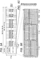
The frame form of multiplex signals in this multiplex
network will be explained in the following. Figs. 5A, 5B and
5C show the frame form of the multiplex signal on the OC-12
path (622.08 MHz) stated in the SONET standard. In this frame
form, the signals of 36 leading octets in Fig. 5A are the
transport overhead and the rest are the payload of multiplex
main signals. Fig. 5B shows the details of the transport
overhead, and Fig. 5C shows the content of the 1-octet STS path
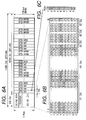
overhead (POH). Figs. 6A, 6B and 6C show the frame form of the
multiplex signal on the OC-192 path (9953.28 MHz) stated in
the SONET standard. In this frame form, the signals of 576
leading octets in Fig. 6A are the transport overhead and the
rest are the payload of multiplex main signals. Figs. 6B and
6C show the details of the transport overhead and the content
of the POH, respectively.
Among the transport overheads shown in Figs. 5B and 6B,
columns 1, 2 and 3 are called "section overhead". The section
overhead is used for the OAM&P of each path segment (defined
to be "section") between transmission units or relay units.
A section overhead created by one transmission unit (or relay
unit) is sent to the neighboring unit over the transmission
path, and terminated by it. Columns 5 through 9 of the transport
overhead is called "line overhead". The line overhead is used
for the OAM&P of each path segment (defined to be "line") between
transmission units which deal with multiplex main signals. A
line overhead created by one transmission unit is sent to the
neighboring unit via a transmission path and relay unit, and
terminated by it. Bytes on row 4 of the transport overhead are
pointers. Indicated by "X" are unused bytes (undefined areas).
In regard to the undefined area, the suggestive article
T1X1.5/96-085 addressed to ANSI describes a concept of
inserting the APS bytes from a OC-M network into the undefined
areas of the line overhead of the transmission frame of OC-N
(N is greater than M).
The functions of individual parts of transport overhead
are as shown in Fig. 4. Among the items of the section overhead,
A1 and A2 are for framing, B1 is for error monitoring within
the section layer, D1-D3 are for OAM, especially data
communication, E1 is for voice communication, J0 is for section
tracing, and Z0 is reserved for future use. Among the items
of the line overhead, H1 and H2 are for indicating the first
byte of STS synchronous payload envelope, H3 is for frequency
justification, B2 and M1 are for error monitoring within the
line layer, K1 and K2 are for automatic protection switch
signaling and alarm transport, D4-D12 are for OAM, E2 is for
voice communication, S1 is the synchronization status, and Z1
and Z2 are reserved for future use. These frame form and
functions are all stated in the above-mentioned standards.
The following explains how various OAM&P information
issued by the multiplex unit A and D are placed in which
locations of the undefined area of the OC-192 transport overhead
or sent by through-transport by the units F and G.
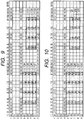
Fig. 7 shows the OC-192 transmission frame, in which the
areas enclosed by the bold line are locations 1000, 1100 and
1200 allotted to through-bytes (bytes to be transported
through). In case the low-speed signal to be multiplexed is
OC-12, the areas indicated by (a), (b) and (c) in Fig. 7 have
detailed forms as shown for example in Figs. 8, 9 and 10,
respectively. In these figures, the areas enclosed by the bold
line are locations 1001-1004, 1101-1107, and 1201-1208
allotted to the through-bytes.
The multiplex units F and G insert the APS bytes of the
OC-12 transmission frame coming from the units A and D, i.e.,
K1 and K2 bytes, into the locations indicated by "Trb.K1" and
"Trb.K2" in Fig. 7. More detailed locations of insertion are
shown by "K1Tr#i" 1104 in Fig. 9 and "K2Tr#i" 1204 in Fig. 10
(where i is an integer greater than 0 and smaller than 16).
Areas used for the through-transport of OAM&P information other
than the APS bytes, e.g., bytes D4-D12, are indicated by
"Trb.D4" through "Trb.D12" in Fig. 7, and these areas are shown
in more detail in Figs. 8, 9 and 10. The OAM&P information may
be placed in any undefined area of the line overhead, instead
of the above example shown in Figs. 8, 9 and 10.
The following deals with the occurrence of a fault on a
transmission path in the multiplex network shown in Fig. 1
during the transmission of a multiplex signal having the
above-mentioned frame form.
Fig. 2 shows the case of a line break occurring on the
OC-12 path of the direction from unit A to unit F. The unit
F detects the loss of signal (LOS) for the incoming signal from
the OC-12 path, and then suspends the through-transport of the
APS bytes from unit A to unit G. Specifically, the unit F
inserts, into the locations indicated by "K1Tr#i" in Fig. 9
and "K2Tr#i" in Fig. 10 (where i is an integer greater than
0 and smaller than 16), a signal having low-order 3 bits of
"111" at least for the "K2Tr#i". This signal can be, "11111111",
i.e., "FF" in hexadecimal, for example. The unit F keeps
inserting the signal in each frame until the transmission path
recovers from the fault.
The unit G inserts intact the received APS bytes which
have been transported through, i.e., the contents of "K1Tr#i"
in Fig. 9 and "K2Tr#i" in Fig. 10, into the defined areas for
the APS bytes in the OC-12 transport overhead, i.e., locations
of K1 and K2 in Fig. 5B, and sends the resulting APS bytes to
the unit D. Accordingly, the unit D receives the APS bytes of
"11111111" from the unit G.
It is stated in the SONET standard that the reception of
the K2 byte having low-order 3 bits of "111" for five consecutive
frames or more indicates the transport of AIS-L which is the
line layer alarm. The standard also states the AIS-L to be one
of the alarms which cause the BLSR switching. Accordingly, the
unit D determines the transport of line layer alarm AIS-L from
the unit G. Namely, the alarm which causes the BLSR switching
is transported up to the multiplex unit D.
In consequence of the foregoing development following the
occurrence of the fault shown in Fig. 2, the BLSR switching
is implemented for the path section between the units A and
D, and the STS-3 like path shown by the dashed line between
the units A and D is relieved. Specifically, the APS bytes are
transacted between the units A and D by way of the unit E until
the BLSR switching completes, while at the same time the APS
bytes are sent by through-transport from unit D to unit A via
the OC-192 path continuously in the same manner as the case
shown in Fig. 1.
The transport of alarm from unit A to unit D via the OC-192
path continues even after the BLSR switching has completed until
the transmission path recovers from the fault. After the
recovery of the fault, the unit F sends by through-transport
intact the APS bytes coming from the unit A to the unit G in
the same manner as shown in Fig. 1. The unit D does not detect
the alarm any longer, and the OC-12 network recovers from the
BLSR switching state to restore the normal operation shown in
Fig. 1.
Based on this transmission scheme, at the occurrence of
a fault on the transmission path which is immediately preceding
the multiplexing to the OC-192 signal, it is possible to
transport the alarm which is needed for the protection switching
of transmission paths in the OC-12 network, irrespective of
the presence or absence of a section terminating equipment such
as a repeater in the high-speed OC-192 path section, whereby
a multiplex transmission apparatus and multiplex transmission
network which are independent of the alteration of network
configuration and have the superior OAM&P functions can readily
be accomplished.
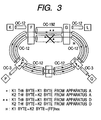
Fig. 3 shows the case of line breaks occurring
simultaneously on the working and protection lines of the OC-192
path of the direction from unit F to unit G. Due to the line
breakage, the protection switching of the OC-192 path does not
take place.
The unit G detects the LOS for the incoming signal from
the OC-192 path, and then inserts, into certain locations for
the APS bytes (K1 and K2) of the OC-12 transport overhead, a
signal having low-order 3 bits of "111" at least for the K2
byte. This signal can be "11111111", i.e., "FF" in hexadecimal,
for example. The unit G keeps inserting the signal in each frame
and sending the resulting APS bytes to the unit D until the
transmission path recovers from the fault.
On receiving the signal, the unit D determines the
transport of line layer alarm AIS-L from the unit G. It means
that the alarm which causes the BLSR switching is transported
up to the unit D. In consequence, the BLSR switching is
implemented for the path section between the units A and D,
and the STS-3 like path shown by the dashed line between the
units A and D is relieved as shown in Fig. 3.
Consequently, at the occurrence of a fault which is
irrecoverable by the protection switching on the OC-192 path,
it is possible to transport the alarm which is needed for the
protection switching of transmission paths in the OC-12 network,
irrespective of the presence or absence of a section terminating
equipment such as a repeater in the high-speed OC-192 path
section, whereby a multiplex transmission apparatus and
multiplex transmission network which are independent of the
alteration of network configuration and have the superior OAM&P
functions can readily be accomplished.
Although the embodiments shown in Fig. 2 and Fig. 3 are
of the cases of line breakage on the transmission paths, these
schemes are also applicable to other faults caused by the
degradation of transmission path, provided that a multiplex
unit which receives the signal of fault occurrence can detect
the LOF and AIS-L and the SF and SD related to the deterioration
of error rate of the transmission path.
Specifically, at the occurrence of this kind of fault on
a low-speed OC-M path which is immediately preceding the
multiplexing to a high-speed path of OC-N (N is greater than
M) as shown in Fig. 2, the above-mentioned alarm is inserted
into a certain location of the undefined area of the transport
overhead of the OC-N frame and sent by through-transport through
the high-speed OC-N path, so that the protection switching
operation of the low-speed OC-M path is induced. At the
occurrence of this kind of fault on a high-speed OC-N path which
is immediately preceding the demultiplexing to a low-speed OC-M
path as shown in Fig. 3, the above-mentioned alarm is inserted
directly into the APS bytes of the OC-M frame and sent to the
low-speed OC-M path, so that the protection switching operation
of the low-speed path is induced.
This alarm transport scheme is also applicable to the case
of sending by through-transport the OAM&P information of the
low-speed network through the high-speed network by way of three
nodes, as will be explained in the following embodiment. The
term "node" signifies a multiplex unit having at least both
the section termination function and line termination
function.
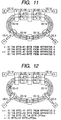
Fig. 11 shows a multiplex network in which the OC-192
network includes three OC-192 multiplex units F, H and G
connected tandem. The figure shows the normal state of the
network without a fault in all path sections among the units
A, F, H, G, D and E. This network configuration is exactly the
same as that shown in Fig. 1, except for the presence of the
unit H. The OC-192 path is of the four-fiber type, with its
protection switching scheme being linear 1+1. The OAM&P
information of the low-speed network is placed in the same
undefined areas of the OC-192 transport overhead as in the case
of the preceding embodiment.
The multiplex unit H is of the ADM type, which will be
explained later. The OC-12 path of BLSR network is not
demultiplexed at the unit H, but it merely serves for the
through-transport of the high-speed signal of OC-192 of one
direction and the high-speed signal of OC-192 of another
direction. Specifically, the STS-12 like path from the unit
A multiplexed by the unit F is demultiplexed entirely by the
unit G, and it reaches the unit D via the OC-12 path. Another
STS-12 like path from the unit D multiplexed by the unit G is
demultiplexed entirely by the unit F, and it reaches the unit
A via the OC-12 path.
The multiplex unit H inserts intact the contents of the
undefined areas (e.g., "K1Tr#i" in Fig. 9 and "K2Tr#i" in Fig.
10) in the OC-192 transport overhead, which are reserved for
the through-transport of APS bytes in the OC-192 transmission
frame received from the unit F, into the undefined areas (e.g.,
"K1Tr#j" in Fig. 9 and "K2Tr#j" in Fig. 10) in the OC-192
transport overhead which are reserved for the through-transport
of APS bytes in the OC-192 transmission frame to be
sent to the unit G. The arguments i and j can be a same integer
or different integers greater than 0 and smaller than 16. For
example, in case the time slot position allotted to the STS-12
like path from the OC-12 BLSR in the OC-192 frame is not
converted at the front and end of the unit H, a same value is
set to the arguments i and j. Otherwise, in the case of the
conversion of time slot position, the value corresponding to
the time slot position after conversion is set to the argument
j. In any case, at demultiplexing by the units F and G, the
"K1Tr#j" and "K2Tr#j" corresponding to the "K1Tr#i" and
"K2Tr#i" are demultiplexed. For the sake of simplicity of the
following explanation, the arguments i and j are given the same
value as the case without the conversion of time slot position.
Fig. 12 shows the case of a fault such as a line break
occurring on the OC-12 path of the direction from unit A to
unit F. The units F and G have the same operations as the
preceding case of Fig. 2, while the unit H has the same operation
as the preceding case of Fig. 11. Specifically, the unit F
detects the LOS for the incoming signal from the OC-12 path,
and, at the through-transport of the APS bytes from unit A to
unit G, it inserts, in the undefined areas (e.g., "K1Tr#i" in
Fig. 9 and "K2Tr#i" in Fig. 10) in the OC-192 transport overhead
which are reserved for the through-transport of APS bytes, a
signal having low-order 3 bits of "111" at least for the "K2Tr#i".
This signal can be "11111111", i.e., "FF" in hexadecimal, for
example. The unit F keeps inserting the signal in each frame
until the transmission path recovers from the fault.
The unit G inserts intact the contents of the received
APS bytes which have been transported through, i.e., "K1Tr#i"
in Fig. 9 and "K2Tr#i" in Fig. 10, into the defined areas for
the APS bytes (K1 and K2) in the OC-12 transport overhead, and
sends the resulting APS bytes to the unit D in the same manner
as the operation of Fig. 11.
The unit D determines the transport of line layer alarm
AIS-L from the unit G. It means that the alarm which causes
the BLSR switching is transported up to the unit D. In
consequence, the BLSR switching is implemented for the path
section between the units A and D in the OC-12 network, and
the STS-3 like path shown by the dashed line between the units
A and D is relieved.
Consequently, at the occurrence of a fault on the OC-12
path which is immediately preceding the multiplexing to the
high-speed OC-192 signal, it is possible to transport the alarm
which is needed for the protection switching of transmission
paths in the OC-12 network, irrespective of the presence or
absence of a section terminating equipment such as a repeater
in the high-speed OC-192 path section, whereby a multiplex
transmission apparatus and multiplex transmission network
which are independent of the alteration of network
configuration and have the superior OAM&P functions can readily
be accomplished.
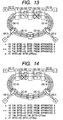
Fig. 13 shows the case of faults such as simultaneous line
breaks occurring on the working and protection lines of the
OC-192 path of the direction from unit H to unit G. Due to the
line breakage, the protection switching of the OC-192 path does
not take place.
The units F and G have the same operations as the preceding
case of Fig. 3, while the unit H has the same operation as the
preceding case of Fig. 11. Specifically, the unit G detects
the LOS for the incoming signal from the OC-192 path, and then
inserts, to the locations of K1 and K2 of the OC-12 transport
overhead, a signal having low-order 3 bits of "111" at least
for the K2 byte. This signal can be "11111111", i.e., "FF" in
hexadecimal, for example. The unit G keeps inserting the
signal in each frame and sending the resulting APS bytes to
the unit D until the transmission path recovers from the fault.
The unit D determines the transport of line layer alarm
AIS-L from the unit G as in the case of Fig. 2. It means that
the alarm which causes the BLSR switching is transported up
to the unit D. In consequence, the BLSR switching is
implemented for the path section between the units A and D,
and the STS-3 like path shown by the dashed line between the
units A and D is relieved.
Consequently, at the occurrence of a fault which is
irrecoverable by the protection switching on the high-speed
OC-192, it is possible to transport the alarm which is needed
for the protection switching of transmission paths in the OC-12
network, irrespective of the presence or absence of a section
terminating equipment such as a repeater in the high-speed
OC-192 path, whereby a multiplex transmission apparatus and
multiplex transmission network which are independent of the
alteration of network configuration and have the superior OAM&P
functions can readily be accomplished.
Fig. 14 shows the case of faults such as simultaneous line
breaks occurring on the working and protection lines of the
OC-192 path of the direction from unit F to unit H. Due to the
line breakage, the protection switching of the OC-192 path does
not take place. The units F and G have the same operations as
the preceding case of Fig. 11, and only the unit H operates
differently from the case of Fig. 11, as will be explained in
the following.
The unit H detects the LOS for the incoming signal from
the OC-192 path, and then it inserts a signal having low-order
3 bits of "111" at least for the "K2Tr#i" out of the "K1Tr#i"
and "K2Tr#i" which are sent to the unit G. This signal can be
"11111111", i.e., "FF" in hexadecimal, for example. The unit
H keeps inserting the signal in each frame and sending the
resulting APS bytes to the unit G until the transmission path
recovers from the fault.
The unit G inserts intact the contents of the received
APS bytes which have been transported through, i.e., "K1Tr#i"
in Fig. 9 and "K2Tr#i" in Fig. 10, into the defined areas for
the APS bytes (K1 and K2) in the OC-12 transport overhead, and
sends the resulting APS bytes to the unit D in the same manner
as the operation of Fig. 11.
The unit D determines the transport of line layer alarm
AIS-L from the unit G, as in the case of Fig. 2. It means that
the alarm which causes the BLSR switching is transported up
to the unit D. In consequence, the BLSR switching is
implemented for the path section between the units A and D in
the OC-12 network, and the STS-3 like path shown by the dashed
line between the units A and D is relieved.
Consequently, at the occurrence of a fault path which is
irrecoverable by the protection switching on the high-speed
OC-192 path, it is possible to transport the alarm which is
needed for the protection switching of transmission paths in
the OC-12 network, irrespective of the presence or absence of
a section terminating equipment such as a repeater in the
high-speed OC-192 path section, whereby a multiplex
transmission apparatus and multiplex transmission network
which are independent of the alteration of network
configuration and have the superior OAM&P functions can readily
be accomplished.
Although the embodiments shown in Fig. 11 through Fig.
14 are of the cases of line breakage on the transmission paths,
these schemes are also applicable to other faults caused by
the degradation of transmission path, provided that a multiplex
unit which receives the signal of fault occurrence can detect
the LOF and AIS-L and the SF and SD related to the deterioration
of error rate of the transmission path.
Specifically, at the occurrence of any of these faults
on a low-speed OC-M path which is immediately preceding the
multiplexing to a high-speed path of OC-N (N is greater than
M) as shown in Fig. 12, the above-mentioned alarm is inserted
into a certain location of the undefined area of the transport
overhead of the OC-N frame and sent by through-transport through
the high-speed OC-N path, so that the protection switching
operation of the low-speed OC-M path is induced. At the
occurrence of any of these faults on a high-speed OC-N path
which is immediately preceding the demultiplexing to a
low-speed OC-M path as shown in Fig. 13, the above-mentioned
alarm is inserted directly into the APS bytes of the OC-M frame
and sent to the low-speed path, so that the protection switching
operation of the low-speed path is induced. At the occurrence
of any of these faults on a high-speed OC-N path which is
immediately preceding the intermediate node on that path as
shown in Fig. 14, the above-mentioned alarm is inserted into
a certain location of the undefined area of the transport
overhead of the OC-N frame and sent by through-transport through
the remaining section of the high-speed path, so that the
protection switching operation of the low-speed path is
induced.
Although the foregoing embodiments shown in Fig. 11
through Fig. 14 are the transport of alarm of the case of the
high-speed network having three nodes, the number of nodes may
be more than three. In case it is intended to feed through the
maintenance information of the low-speed network through a
section of the high-speed network, the processes carried out
by the nodes at both ends of the high-speed network are the
same as those of the multiplex units F and G and the process
of all nodes existing in that section are the same as that of
the unit H explained above.
Although the foregoing embodiments shown in Fig. 1 through
Fig. 3 and Fig. 11 through Fig. 14 are of the case of the
high-speed OC-192 path and its protection switching scheme of
linear 1+1 of four-fiber type, they may be linear 1:N (N is
an integer greater than 0), BLSR of four-fiber type, or BLSR
of two-fiber type. The switching scheme of linear 1:N is stated
in the ANSI Recommendation T1.105.01 of the SONET standard and
in the ITU-T Recommendation G.783 of the SDH standard. In any
switching scheme, the low-speed network detects the AIS-L alarm
at the occurrence of a fault on the OC-12 path which is
immediately preceding the multiplexing to the high-speed
OC-192 signal, or at the occurrence of a fault which is
irrecoverable by the protection switching on the high-speed
OC-192 path. Based on this scheme, it is possible to implement
the protection switching of transmission paths in the OC-12
network reliably.
Although the foregoing embodiments are of the case of the
low-speed OC-12 network being a BLSR, it may be a so-called
linear-type network having a protection switching scheme of
linear 1+1 or linear 1:N (N is an integer greater than 0). In
any switching scheme, causes of switching include the AIS-L
alarm, and therefore at the occurrence of a fault on the OC-12
path which is immediately preceding the multiplexing to the
high-speed OC-192 signal, or at the occurrence of a fault which
is irrecoverable by the protection switching on the high-speed
OC-192 path, it is possible to implement the protection
switching of transmission paths in the OC-12 network reliably.
Although in the foregoing embodiments, the low-speed
network and the high-speed network, with the former being
multiplexed to the latter, have transmission speeds of OC-12
and OC-192, respectively, the low-speed and high-speed
networks can generically have speeds of OC-M and OC-N, where
N is a multiple of M. Although in the foregoing embodiments
of Fig. 11 through Fig. 14, the high-speed paths between the
multiplex units F and H and between H and G have a same
transmission speed of OC-192, these sections may have different
speeds. For example, the path between the units F and H has
speed OC-N' and the path between the units H and G has speed
OC-N, where N and N' are both multiples of M.
Although in the foregoing embodiments, the "K1Tr#i" and
"K2Tr#i" defined in the undefined area of the line overhead
of the OC-N frame are used for the transport of alarm through
the high-speed OC-N path section, an alternative scheme is to
define multiple bytes dedicated to alarm transport (will be
called "TTAIS bytes") in correspondence to multiple low-speed
signals to be multiplexed. For example, the multiplex unit F,
which has detected a fault on the low-speed OC-M path
immediately preceding the multiplexing to the high-speed path,
inserts a certain code, e.g., "F0" in hexadecimal, indicative
of the alarm to the corresponding TTAIS byte and sends the
resulting byte to the high-speed path OC-N (N is greater than
M). The multiplex unit G, when it detects the TTAIS byte of
the alarm code, e.g., "F0" in hexadecimal, from the high-speed
path OC-N or when it detects a fault on the high-speed path
which is immediately preceding the demultiplexing to the
low-speed path, inserts, to the APS bytes, i.e., K1 byte and
K2 byte, of the corresponding OC-M frame, the above-mentioned
alarm, i.e., a signal having low-order 3 bits of "111" at least
for the K2 byte, e.g., "11111111" ("FF" in hexadecimal), and
sends the resulting APS bytes to the low-speed path. The
multiplex unit H which becomes the intermediate node, when it
detects a fault on the high-speed OC-N path, inserts a certain
code, e.g., "F0" in hexadecimal, of the alarm to the TTAIS byte,
and sends the resulting byte to the high-speed OC-N path.
Although in the foregoing embodiments, the alarm
information which has been transported through the high-speed
OC-N path section is sent to the low-speed path by being inserted
into the APS bytes of the transport overhead of the low-speed
OC-M frame, it may be sent to the low-speed path by use of the
framing bytes of transport overhead of the low-speed signal
or, alternatively, the transmission of the low-speed signal
may be halted in response to the through-transported alarm
information having a certain code value indicative of the alarm.
For example, the multiplex unit G, when receiving a
high-speed signal, with its "K1Tr#i" and "K2Tr#i" or its TTAIS
byte being a certain code value, e.g., "FF" in hexadecimal,
indicative of the alarm, it inserts for each frame a value
excluding "F6" and "28" in hexadecimal that are the framing
patterns, e.g., "FF", to the framing bytes, i.e., A1 byte and
A2 byte, of transport overhead of the low-speed signal, and
sends the resulting bytes to the low-speed OC-12 path.
Consequently, the unit D on the low-speed side detects the loss
of frame (LOF). Since the LOF is a cause of switching based
on the BLSR switching schemes of linear 1+1 and linear 1:N,
it is possible to induce the protection switching operation
of the low-speed path.
For another example, the multiplex unit G, when receiving
a high-speed signal, with its "K1Tr#i" and "K2Tr#i" or its TTAIS
byte being a certain code value, e.g., "FF" in hexadecimal,
indicative of the alarm, it halts the transmission of the
corresponding low-speed signal. Consequently, the unit D on
the low-speed side detects the loss of signal (LOS). Since the
LOS is a cause of switching based on the BLSR switching schemes
of linear 1+1 and linear 1:N, it is possible to induce the
protection switching operation of the low-speed path.
The foregoing embodiments use the undefined area of the
line overhead of the OC-N frame for the transport of alarm
through the high-speed OC-N path section. The insertion or
detection of the alarm code at these byte positions is carried
out obviously in the location for the so-called line termination
function or multiplex section termination function stated in
the SONET and SDH standards. For example, in case the alarm
code is inserted into the Trb.K1" or "Trb.K2" of one frame,
these bytes are included in the operation area of the B2 byte
to be inserted into the next frame.
Next, the multiplex equipment used in this invention,
which is of the line terminating equipment (LTE) type or the
add/drop multiplex (ADM) type for example, will be explained.
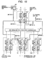
Fig. 15 shows the arrangement of an LTE-type multiplex
equipment. The LTE-type multiplex equipment has functions of
multiplexing low-speed signals (OC-M) into a high-speed signal
(OC-N) and demultiplexing a high-speed signal (OC-N) into
low-speed signals (OC-M). More specifically, it introduces
low-speed multiplex signals consisting of multiple transport
overheads and multiplex main signals and a high-speed multiplex
signal consisting of a transport overhead and multiplex main
signal to implement the processes of termination and
replacement of transport overheads of these multiplex signals,
and carries out the multiplexing and demultiplexing between
the low-speed multiplex main signals and the high-speed
multiplex main signal.
For example, the multiplex equipment introduces 16
low-speed multiplex signals of OC-12, and implements for their
main signals the multiplexing/demultiplexing process and
overhead process in connection with a high-speed multiplex
signal of OC-192 in accordance with the SONET standard. It also
transports through for other multiplex equipment the transport
overheads of the input multiplex signals.
The multiplex equipment, which performs these signal
multiplexing/demultiplexing and overhead process, includes
low-speed signal sending/receiving units 10-1 through 10-M
which receive and release M sets of low-speed multiplex signals
and implement the processes of their transport overheads and
main signals, a high-speed signal sending/receiving unit 11
which receives and releases a high-speed multiplex signal and
implements the processes of its transport overhead and main
signal, a main signal multiplexing/demultiplexing unit 100
which implements the multiplexing and demultiplexing between
the low-speed main signals and high-speed main signal, and a
control unit 400 which controls the whole equipment.
The low-speed signal sending/receiving units 10-1 through
10-M include section overhead (SOH) terminating units 20-1
through 20-M which receive low-speed signals and implement the
termination process for the received section overheads, line
overhead (LOH) terminating units 30-1 through 30-M which
implement the termination process for the received line
overheads, LOH inserting units 80-1 through 80-M which put the
sending line overhead bytes to the outgoing signals, and SOH
inserting units 90-1 through 90-M which put the sending section
overhead bytes to the outgoing signals. Similarly, the
high-speed signal sending/receiving unit 11 includes a SOH
terminating unit 60, a LOH terminating unit 70, a LOH inserting
unit 40, and a SOH inserting unit 50 for the high-speed signals.
Through-transport of OAM&P information signifies that the
OAM&P information in the low-speed signals received by
low-speed units 10-i (1≦i≦M) is sent by through-transport
through the high-speed path by being inserted into the undefined
area of the transport overhead in the high-speed signal to be
sent out of the high-speed unit 11, and the content of the
undefined area of the transport overhead in the high-speed
signal received by the high-speed unit 11 is sent out to the
low-speed paths by being inserted intact into the defined areas
of transport overheads of the low-speed signals to be sent out
of the low-speed units 10-i.
There are three conceivable methods of the transport of
OAM&P information through the equipment, as follows.
Based on the foregoing arrangement, the multiplex
equipment introduces the low-speed and high-speed multiplex
signals, implements the multiplexing and demultiplexing of the
main signals, and feeds through or terminates the overheads
that are predetermined for the network which uses the equipment.
Fig. 16 shows the arrangement of an ADM-type multiplex
equipment. The ADM-type multiplex equipment, which is
connected with high-speed paths (OC-N) on its both sides and
with multiple low-speed paths (OC-M) (M is smaller than or equal
to N), has functions of multiplexing low-speed signals (OC-M)
into a high-speed signal (OC-N) and demultiplexing a high-speed
signal (OC-N) into low-speed signals (OC-M), and further
has functions of replacing the time slots of STS paths between
the high-speed signals (OC-N) and conducting through the time
slots. More specifically1 it introduces low-speed multiplex
signals consisting of multiple transport overheads and
multiplex main signals and two high-speed multiplex signals
consisting of two transport overheads and multiplex main
signals to implement the processes of termination and
replacement of transport overheads of these multiplex signals,
and carries out the addition of the low-speed multiplex main
signals to a high-speed multiplex main signal, the dropping
of the low-speed multiplex main signals from a high-speed
multiplex main signal, and the cross-connection and
through-transport of the high-speed multiplex main signals.
For example, it implements the above-mentioned main
signal process and overhead process stated in the SONET standard
for the low-speed multiplex signals of OC-12 and high-speed
multiplex signals of OC-192, while sending by through-transport
the transport overheads of the incoming multiplex
signals for use in other equipment. The above-mentioned
high-speed and low-speed signals can be signals of the same
speed.
The ADM-type equipment is virtually identical in
arrangement to the LTE-type equipment explained previously,
with the same functional blocks being referred to by the common
symbols in Fig. 15 and Fig. 16. It is converted from the
LTE-type equipment in terms of the disposition and the number
of the functional blocks, and provided additionally with a main
signal adding/dropping unit 105 which implements the addition,
dropping, cross-connection and through-transport of the main
signals. The following explains only portions different from
the LTE-type equipment.
The ADM-type equipment has two high-speed signal
sending/receiving units, i.e., West-side unit 11-1 and
East-side unit 11-2, which are used to connect ADM-type
equipment on its both sides on the high-speed path. In order
to carry out the above-mentioned main signal processing based
on the connection of the high-speed units 11-1 and 11-2 and
low-speed units 10-2 through 10-M or the connection between
the high-speed units 11-1 and 11-2, the additional main signal
adding/dropping unit 105 is disposed between the high-speed
units 11-1 and 11-2 and the main signal
multiplexing/demultiplexing unit 100.
The equipment is designed to transport through the
transport overheads of high-speed multiplex signals based on
any of the Schemes 1, 2 and 3 explained previously in connection
with the LTE-type equipment.
The transmission network arranged with these multiplex
equipment operates to transport the alarm for inducing the
protection switching to the low-speed network at the occurrence
of a fault on the low-speed path which is immediately preceding
the multiplexing to the high-speed network or at the occurrence
of a fault on a high-speed path section, whereby a multiplex
transmission apparatus and multiplex transmission network
which are independent of the alteration of network
configuration and have the superior OAM&P functions,
particularly the protection switching operation, can readily
be accomplished.
According to the present invention, it becomes possible
to realize a method and apparatus for multiplex transmission
which implement the protection switching of transmission paths
reliably.