EP0920107A2 - Winding arrangement for switched reluctance machine based internal starter generator - Google Patents
Winding arrangement for switched reluctance machine based internal starter generator Download PDFInfo
- Publication number
- EP0920107A2 EP0920107A2 EP98308027A EP98308027A EP0920107A2 EP 0920107 A2 EP0920107 A2 EP 0920107A2 EP 98308027 A EP98308027 A EP 98308027A EP 98308027 A EP98308027 A EP 98308027A EP 0920107 A2 EP0920107 A2 EP 0920107A2
- Authority
- EP
- European Patent Office
- Prior art keywords
- inner layer
- winding arrangement
- turn
- stator coil
- coil
- Prior art date
- Legal status (The legal status is an assumption and is not a legal conclusion. Google has not performed a legal analysis and makes no representation as to the accuracy of the status listed.)
- Granted
Links
Images


Classifications
-
- F—MECHANICAL ENGINEERING; LIGHTING; HEATING; WEAPONS; BLASTING
- F02—COMBUSTION ENGINES; HOT-GAS OR COMBUSTION-PRODUCT ENGINE PLANTS
- F02N—STARTING OF COMBUSTION ENGINES; STARTING AIDS FOR SUCH ENGINES, NOT OTHERWISE PROVIDED FOR
- F02N11/00—Starting of engines by means of electric motors
- F02N11/04—Starting of engines by means of electric motors the motors being associated with current generators
-
- H—ELECTRICITY
- H02—GENERATION; CONVERSION OR DISTRIBUTION OF ELECTRIC POWER
- H02K—DYNAMO-ELECTRIC MACHINES
- H02K3/00—Details of windings
- H02K3/04—Windings characterised by the conductor shape, form or construction, e.g. with bar conductors
- H02K3/18—Windings for salient poles
-
- Y—GENERAL TAGGING OF NEW TECHNOLOGICAL DEVELOPMENTS; GENERAL TAGGING OF CROSS-SECTIONAL TECHNOLOGIES SPANNING OVER SEVERAL SECTIONS OF THE IPC; TECHNICAL SUBJECTS COVERED BY FORMER USPC CROSS-REFERENCE ART COLLECTIONS [XRACs] AND DIGESTS
- Y10—TECHNICAL SUBJECTS COVERED BY FORMER USPC
- Y10T—TECHNICAL SUBJECTS COVERED BY FORMER US CLASSIFICATION
- Y10T29/00—Metal working
- Y10T29/49—Method of mechanical manufacture
- Y10T29/49002—Electrical device making
- Y10T29/4902—Electromagnet, transformer or inductor
- Y10T29/49071—Electromagnet, transformer or inductor by winding or coiling
Definitions
- the present invention relates, in general to coil winding arrangements and more particularly to a winding arrangement for an internal starter generator based in a switched reluctance machine.
- Eddy current losses tend to exceed the I 2 R losses in high speed, high power switched reluctance machines as will be utilized for internal jet-engine starter-generators. These machines are characterized by a low number of turns per phase made from rectangular, hollow conductors with outside dimensions of typically 0.090 inch by 0.125 inch or larger. These conductors are exposed to high magnetic fields which change amplitude very rapidly at a rate of typically more than 1000 Hz. the electrical losses in the conductors, generally called I 2 R losses, are much larger than the losses calculated by multiplying the square of the rms value of the winding current times the DC resistance of the conductor. These additional losses are due to eddy currents induced by the rapidly changing magnetic field in the solid walls of the conductor.
- High eddy current losses introduce a number of challenges.
- the cooling required by the high eddy current losses challenges the conventional cooling system for which standard engine lubrication oil is used.
- the adverse impact on efficiency of the system becomes rather significant with high eddy current losses.
- the present invention provides for loss reduction by specific stator coil placement and winding arrangement.
- the first turn of the winding of the coil is directly on top of the second turn in the inside layer of the coil.
- the first turn is moved to the outside, over the second layer; the wire, after completing the first turn, then returns to the inner layer.
- the winding arrangement according to the present invention provides major eddy current loss reduction/prevention compared to the convention winding arrangement, without any significant weight and size impact.
- a stator coil winding arrangement comprises an inner layer and an outer layer which define two layers of the coil. A first turn of the inner layer is positioned over the outer layer and a subsequent turn of the inner layer is positioned over the inner layer.
- the present invention results in major eddy current loss reduction/prevention for internal starter/generators based in switched reluctance machines.
- conventional wisdom dictates using smaller, hollow conductors in parallel. That, however, becomes very quickly impractical because of the very expensive fabrication procedures necessary for these types of coils. Also, since these coils are located in rather wide and open slots, the eddy current effects are more pronounced than in conventional high power machines with deep and narrow slots.
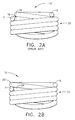
- Figs. 1A and 2A illustrate conventional stator coil winding arrangements 10; while Figs. 1B and 2B illustrate stator coil winding arrangements 12 wound in accordance with the teachings of the present invention.
- the coil winding arrangements 10 and 12 start at point S and end at point F.
- these coils are wound as two layer coils having an outer layer with one less turn than the inner layer, for winding reasons.
- a first turn 14 of the winding of the coil 10 is directly on top of second turn 16 in inside layer 18 of the coil 10.
- top turn 22 which is positioned directly over the inner layer 18 in the prior art, and which is close to the stator pole top (not shown), is actually moved over toward the outside, and positioned directly over outer layer 20. After completing the first turn 22, the coil returns to the inner layer 18 in the second turn 24.
- the winding arrangement of the present invention is feasible and does not require any increased slot depth. Therefore, the winding arrangement of the present invention has the advantage of having little or no weight impact.
- the total losses in the coil are reduced by almost a factor of two, as predicted by time stepping finite element analysis, known and understood by persons skilled in the art.
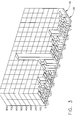
- Fig. 3 The distribution of the losses over the different conductors for two nine turn coils wound in the conventional manner and wound in accordance with the present invention are compared in Fig. 3.
- Fig. 3 different conductors are positioned along the X-axis, and corresponding eddy current losses, measured as W/in, are measured along the Y-axis.
- Conductor row 26 illustrates the loss distribution for conventional coil winding arrangements, while conductor row 28 illustrates the loss distribution for coil winding arrangements in accordance with the present invention.
- conductors C9 and C14 are located at the top of the stator pole (one on each side).
- Fig. 4 the electromagnetics of a switched reluctance machine are shown with rotor core 30 and stator electromagnetics of stator core 32, to illustrate a typical application of the coils of the present invention, and their orientation.
- the coils 10 are embedded in large slots 34 in the stator and wound around individual teeth or poles 36.
- the top 10t of each coil is located adjacent to the air gap between the rotor and stator cores 30 and 32, respectively.
- the bottom 10b of each coil is located adjacent to the bottom of the slot 34 in the stator core. Because of the wide open slots, the top 10t of any coil is exposed to rather high magnetic field levels which, in turn, are responsible for eddy current losses.
- the coil winding arrangement according to the present invention results in major eddy current loss reduction/prevention for internal starter/generators based in switched reluctance machines.
- the two layer coil arrangement of the present invention is applicable to any coil where the top turns are exposed to high flux density fields, changing at frequencies above 100 Hertz.
Landscapes
- Engineering & Computer Science (AREA)
- Power Engineering (AREA)
- Chemical & Material Sciences (AREA)
- Combustion & Propulsion (AREA)
- Mechanical Engineering (AREA)
- General Engineering & Computer Science (AREA)
- Windings For Motors And Generators (AREA)
- Synchronous Machinery (AREA)
Abstract
Description
- The present invention relates, in general to coil winding arrangements and more particularly to a winding arrangement for an internal starter generator based in a switched reluctance machine.
- The invention herein described was made in the performance of work done under Air Force Contract No. F33615-94-C-2504, awarded by the Department of the U.S. Air Force under which the U.S. Government has certain rights.
- Eddy current losses tend to exceed the I2R losses in high speed, high power switched reluctance machines as will be utilized for internal jet-engine starter-generators. These machines are characterized by a low number of turns per phase made from rectangular, hollow conductors with outside dimensions of typically 0.090 inch by 0.125 inch or larger. These conductors are exposed to high magnetic fields which change amplitude very rapidly at a rate of typically more than 1000 Hz. the electrical losses in the conductors, generally called I2R losses, are much larger than the losses calculated by multiplying the square of the rms value of the winding current times the DC resistance of the conductor. These additional losses are due to eddy currents induced by the rapidly changing magnetic field in the solid walls of the conductor. Normally these eddy current losses are between 10 to 80% of the DCI2R losses. However, in high speed, high power switched reluctance machines, the additional losses due to the eddy currents can be a multiple of the DCI2R losses. Applying the same machine type to an internal starter/generator, the power rating and the fundamental frequency can readily be higher than for an external starter generator, potentially resulting in very high eddy current losses.
- High eddy current losses introduce a number of challenges. For example, the cooling required by the high eddy current losses challenges the conventional cooling system for which standard engine lubrication oil is used. Also, the adverse impact on efficiency of the system becomes rather significant with high eddy current losses.
- It would be desirable, then, to be able to reduce the eddy current losses in internal starter/generator arrangements.
- The present invention provides for loss reduction by specific stator coil placement and winding arrangement. In the prior art, the first turn of the winding of the coil is directly on top of the second turn in the inside layer of the coil. With the coil configuration of the present invention, the first turn is moved to the outside, over the second layer; the wire, after completing the first turn, then returns to the inner layer. The winding arrangement according to the present invention provides major eddy current loss reduction/prevention compared to the convention winding arrangement, without any significant weight and size impact.
- In accordance with one aspect of the present invention, a stator coil winding arrangement comprises an inner layer and an outer layer which define two layers of the coil. A first turn of the inner layer is positioned over the outer layer and a subsequent turn of the inner layer is positioned over the inner layer.
- An embodiment of the invention will now be described, by way of example, with reference to the accompanying drawings, in which:-
- Figs. 1A and 2A illustrate an isometric view and a front view, respectively, of a conventional coil winding arrangement;
- Figs. 1B and 2B illustrate an isometric view and a front view, respectively, of a coil winding arrangement in accordance with the present invention;
- Fig. 3 is a graph comparing distribution of eddy current losses over different conductors wound as in Figs. 1A and 2A, to losses over conductors wound in accordance with the present invention as shown in Figs. 1B and 2B; and
- Fig. 4 illustrates an application of the coil winding arrangement of the present invention, with switched reluctance machine electromagnetics.
-
- The present invention will be described with respect to winding arrangements for switched reluctance machine based internal starter generators; those skilled in the art, however, will recognize that the principles of the present invention could be easily adapted or modified for use on a variety of components.
- The present invention results in major eddy current loss reduction/prevention for internal starter/generators based in switched reluctance machines. To reduce eddy current losses, conventional wisdom dictates using smaller, hollow conductors in parallel. That, however, becomes very quickly impractical because of the very expensive fabrication procedures necessary for these types of coils. Also, since these coils are located in rather wide and open slots, the eddy current effects are more pronounced than in conventional high power machines with deep and narrow slots.
- Referring to the drawings, Figs. 1A and 2A illustrate conventional stator
coil winding arrangements 10; while Figs. 1B and 2B illustrate statorcoil winding arrangements 12 wound in accordance with the teachings of the present invention. Thecoil winding arrangements first turn 14 of the winding of thecoil 10 is directly on top ofsecond turn 16 ininside layer 18 of thecoil 10. - With the coil configuration of the present invention, illustrated in Figs. 1B and 2B,
top turn 22, which is positioned directly over theinner layer 18 in the prior art, and which is close to the stator pole top (not shown), is actually moved over toward the outside, and positioned directly overouter layer 20. After completing thefirst turn 22, the coil returns to theinner layer 18 in thesecond turn 24. - The winding arrangement of the present invention is feasible and does not require any increased slot depth. Therefore, the winding arrangement of the present invention has the advantage of having little or no weight impact. The total losses in the coil are reduced by almost a factor of two, as predicted by time stepping finite element analysis, known and understood by persons skilled in the art.
- The distribution of the losses over the different conductors for two nine turn coils wound in the conventional manner and wound in accordance with the present invention are compared in Fig. 3. In Fig. 3, different conductors are positioned along the X-axis, and corresponding eddy current losses, measured as W/in, are measured along the Y-axis.
Conductor row 26 illustrates the loss distribution for conventional coil winding arrangements, whileconductor row 28 illustrates the loss distribution for coil winding arrangements in accordance with the present invention. In Fig. 3, conductors C9 and C14 are located at the top of the stator pole (one on each side). - It is clear from Fig. 3 that not only are the losses in the top conductor (C9 and C14) reduced, but because of the changed flux distribution, the majority of the conductors show a reduction in total losses, when wound in accordance with the present invention. Consequently, the present invention allows a major eddy current loss reduction/prevention, as compared to convention stator coil winding arrangements, without any significant weight and size impact.
- In Fig. 4, the electromagnetics of a switched reluctance machine are shown with
rotor core 30 and stator electromagnetics ofstator core 32, to illustrate a typical application of the coils of the present invention, and their orientation. Thecoils 10 are embedded inlarge slots 34 in the stator and wound around individual teeth orpoles 36. The top 10t of each coil is located adjacent to the air gap between the rotor andstator cores bottom 10b of each coil is located adjacent to the bottom of theslot 34 in the stator core. Because of the wide open slots, the top 10t of any coil is exposed to rather high magnetic field levels which, in turn, are responsible for eddy current losses. The coil winding arrangement according to the present invention results in major eddy current loss reduction/prevention for internal starter/generators based in switched reluctance machines. - While preferred embodiments of the present invention have been shown and described herein, it will be obvious to those skilled in the art that such embodiments are provided by way of example only. Numerous variations, changes, and substitutions will now occur to those skilled in the art without departing from the invention, and those skilled in the art will recognize that the principles of the present invention could be easily adapted or modified to achieve goals in various arrangements. In particular, the two layer coil arrangement of the present invention is applicable to any coil where the top turns are exposed to high flux density fields, changing at frequencies above 100 Hertz.
Claims (5)
- A stator coil winding arrangement comprising:an inner layer and an outer layer for defining two layers of the coil;a first turn of the inner layer positioned over the outer layer;a subsequent turn of the inner layer positioned over the inner layer.
- A stator coil winding arrangement as claimed in claim 1 wherein the outer layer comprises one less turn than the inner layer.
- A stator coil winding arrangement as claimed in claim 1 wherein total losses in the stator coil are reduced by approximately a factor of two.
- A stator coil winding arrangement as claimed in claim 1 further comprising a plurality of turns of the inner layer subsequent to the first turn of the inner layer, each of the subsequent plurality of turns of the inner layer positioned over the inner layer.
- A stator coil winding arrangement as claimed in claim 1 wherein the stator coil is embedded in a large slot in the stator and wound around individual poles.
Applications Claiming Priority (2)
| Application Number | Priority Date | Filing Date | Title |
|---|---|---|---|
| US982002 | 1997-12-01 | ||
| US08/982,002 US6255756B1 (en) | 1997-12-01 | 1997-12-01 | Winding arrangement for switched reluctance machine based internal starter generator |
Publications (3)
| Publication Number | Publication Date |
|---|---|
| EP0920107A2 true EP0920107A2 (en) | 1999-06-02 |
| EP0920107A3 EP0920107A3 (en) | 2000-12-20 |
| EP0920107B1 EP0920107B1 (en) | 2004-09-22 |
Family
ID=25528782
Family Applications (1)
| Application Number | Title | Priority Date | Filing Date |
|---|---|---|---|
| EP98308027A Expired - Lifetime EP0920107B1 (en) | 1997-12-01 | 1998-10-01 | Winding arrangement for switched reluctance machine based internal starter generator |
Country Status (4)
| Country | Link |
|---|---|
| US (1) | US6255756B1 (en) |
| EP (1) | EP0920107B1 (en) |
| JP (1) | JP3566559B2 (en) |
| DE (1) | DE69826419T2 (en) |
Cited By (5)
| Publication number | Priority date | Publication date | Assignee | Title |
|---|---|---|---|---|
| FR2869474A1 (en) * | 2004-04-26 | 2005-10-28 | Denso Corp | CONCENTRATED WINDING STATOR COIL FOR A ROTATING ELECTRICAL MACHINE |
| FR2869473A1 (en) * | 2004-04-26 | 2005-10-28 | Denso Corp | CONCENTRATED WINDING STATOR COIL FOR AN ELECTRIC ROTATING MACHINE |
| FR2890798A1 (en) * | 2005-09-13 | 2007-03-16 | Valeo Equip Electr Moteur | STATOR FOR AN ALTERNATOR OR ALTERNO-STARTER TYPE POLYPHASE ELECTRICAL ROTATING MACHINE |
| WO2008113086A2 (en) * | 2007-03-16 | 2008-09-25 | Egston System Electronics Eggenburg Gmbh | Method for the mechanical winding of a coil |
| EP3706290A1 (en) | 2019-03-05 | 2020-09-09 | Kongsberg Maritime CM AS | Method for winding of a concentrated coil for an electric machine |
Families Citing this family (22)
| Publication number | Priority date | Publication date | Assignee | Title |
|---|---|---|---|---|
| US6699081B1 (en) | 2003-01-16 | 2004-03-02 | Brunswick Corporation | Marine propulsion device with a switched reluctance starter motor and generator system |
| JP3903922B2 (en) * | 2003-01-27 | 2007-04-11 | 株式会社デンソー | Concentrated winding stator coil of rotating electric machine |
| US7119467B2 (en) | 2003-03-21 | 2006-10-10 | Pratt & Whitney Canada Corp. | Current limiting means for a generator |
| US6920023B2 (en) * | 2003-03-21 | 2005-07-19 | Pratt & Whitney Canada Corp. | Current limiting means for a generator |
| US6965183B2 (en) * | 2003-05-27 | 2005-11-15 | Pratt & Whitney Canada Corp. | Architecture for electric machine |
| US7583063B2 (en) | 2003-05-27 | 2009-09-01 | Pratt & Whitney Canada Corp. | Architecture for electric machine |
| US7262539B2 (en) * | 2004-11-26 | 2007-08-28 | Pratt & Whitney Canada Corp. | Saturation control of electric machine |
| US7545056B2 (en) * | 2003-05-27 | 2009-06-09 | Pratt & Whitney Canada Corp. | Saturation control of electric machine |
| US7253548B2 (en) | 2003-06-16 | 2007-08-07 | Pratt & Whitney Canada Corp. | Method and apparatus for controlling an electric machine |
| JP4148115B2 (en) * | 2003-12-02 | 2008-09-10 | 株式会社村田製作所 | Coil winding method and coil component using the same |
| JP2005312182A (en) * | 2004-04-21 | 2005-11-04 | Denso Corp | Concentrated winding stator coil of rotary electric machine |
| US7288923B1 (en) | 2006-04-21 | 2007-10-30 | Pratt & Whitney Canada Corp. | Voltage-limited electric machine |
| US7719147B2 (en) | 2006-07-26 | 2010-05-18 | Millennial Research Corporation | Electric motor |
| JP5315743B2 (en) * | 2008-03-26 | 2013-10-16 | アイシン精機株式会社 | Electric rotary motor |
| WO2009137623A2 (en) * | 2008-05-06 | 2009-11-12 | Millenial Research Corporation | Apparatus and system for efficiently controlling a hub motor |
| US10038349B2 (en) | 2008-08-15 | 2018-07-31 | Millennial Research Corporation | Multi-phase modular coil element for electric motor and generator |
| WO2010019951A1 (en) | 2008-08-15 | 2010-02-18 | Millennial Research Corporation | Regenerative motor and coil |
| CA2690309A1 (en) * | 2009-01-15 | 2010-07-15 | Eric Nadeau | Electric motor |
| CN102474145B (en) * | 2009-06-29 | 2014-02-19 | 丰田自动车株式会社 | Multilayered wound coil, stator, and manufacturing method therefor |
| US20110062805A1 (en) * | 2009-09-17 | 2011-03-17 | Caterpillar Inc. | Switched reluctance machine with eddy current loss dampener |
| CN105493383B (en) * | 2013-10-30 | 2018-09-18 | 三菱电机株式会社 | Motor and the manufacturing method for having its compressor, motor |
| KR20220127558A (en) * | 2021-03-11 | 2022-09-20 | 엘지이노텍 주식회사 | Motor |
Citations (2)
| Publication number | Priority date | Publication date | Assignee | Title |
|---|---|---|---|---|
| US1451374A (en) * | 1919-08-15 | 1923-04-10 | Remy Electric Co | Construction of electrical windings |
| US4794361A (en) * | 1988-03-10 | 1988-12-27 | General Motors Corporation | Coil winding method for maximum utilization of winding envelope |
Family Cites Families (7)
| Publication number | Priority date | Publication date | Assignee | Title |
|---|---|---|---|---|
| US3802066A (en) | 1972-04-06 | 1974-04-09 | Zenner W | Assembly method for stator or dynamo-electric machine |
| FR2181464B1 (en) * | 1972-04-25 | 1976-08-06 | Barthalon Maurice | |
| US4131988A (en) * | 1976-10-29 | 1979-01-02 | The Globe Tool And Engineering Company | Method of manufacturing a dynamoelectric field member |
| US4684867A (en) | 1984-05-31 | 1987-08-04 | General Electric Company | Regenerative unipolar converter for switched reluctance motors using one main switching device per phase |
| JPH0815376B2 (en) * | 1984-11-09 | 1996-02-14 | 株式会社北斗製作所 | Winding method and winding device for multilayer air-core coil using self-bonding electric wire |
| US4967464A (en) | 1989-03-24 | 1990-11-06 | General Electric Company | Method of making a switched reluctance motor having plural-stage form-wound coil winding |
| US5376851A (en) | 1992-05-18 | 1994-12-27 | Electric Power Research Institute, Inc. | Variable reluctance motor with full and short pitch windings |
-
1997
- 1997-12-01 US US08/982,002 patent/US6255756B1/en not_active Expired - Fee Related
-
1998
- 1998-09-30 JP JP27686098A patent/JP3566559B2/en not_active Expired - Fee Related
- 1998-10-01 DE DE69826419T patent/DE69826419T2/en not_active Expired - Fee Related
- 1998-10-01 EP EP98308027A patent/EP0920107B1/en not_active Expired - Lifetime
Patent Citations (2)
| Publication number | Priority date | Publication date | Assignee | Title |
|---|---|---|---|---|
| US1451374A (en) * | 1919-08-15 | 1923-04-10 | Remy Electric Co | Construction of electrical windings |
| US4794361A (en) * | 1988-03-10 | 1988-12-27 | General Motors Corporation | Coil winding method for maximum utilization of winding envelope |
Cited By (11)
| Publication number | Priority date | Publication date | Assignee | Title |
|---|---|---|---|---|
| FR2869474A1 (en) * | 2004-04-26 | 2005-10-28 | Denso Corp | CONCENTRATED WINDING STATOR COIL FOR A ROTATING ELECTRICAL MACHINE |
| FR2869473A1 (en) * | 2004-04-26 | 2005-10-28 | Denso Corp | CONCENTRATED WINDING STATOR COIL FOR AN ELECTRIC ROTATING MACHINE |
| US7126247B2 (en) | 2004-04-26 | 2006-10-24 | Denso Corporation | Concentrated winding stator coil for an electric rotary machine |
| US7262538B2 (en) | 2004-04-26 | 2007-08-28 | Denso Corporation | Concentrated winding stator coil for an electric rotary machine |
| FR2890798A1 (en) * | 2005-09-13 | 2007-03-16 | Valeo Equip Electr Moteur | STATOR FOR AN ALTERNATOR OR ALTERNO-STARTER TYPE POLYPHASE ELECTRICAL ROTATING MACHINE |
| WO2007031679A2 (en) * | 2005-09-13 | 2007-03-22 | Valeo Equipements Electriques Moteur | Polyphase stator of a rotating electrical machine with claw-pole rotor and alternator or alternator starter comprising same |
| WO2007031679A3 (en) * | 2005-09-13 | 2007-08-02 | Valeo Equip Electr Moteur | Polyphase stator of a rotating electrical machine with claw-pole rotor and alternator or alternator starter comprising same |
| WO2008113086A2 (en) * | 2007-03-16 | 2008-09-25 | Egston System Electronics Eggenburg Gmbh | Method for the mechanical winding of a coil |
| WO2008113086A3 (en) * | 2007-03-16 | 2008-11-06 | Egston System Electronics Egge | Method for the mechanical winding of a coil |
| US8450900B2 (en) | 2007-03-16 | 2013-05-28 | Egston System Electronics Eggenburg Gmbh | Method for the mechanical winding of a coil |
| EP3706290A1 (en) | 2019-03-05 | 2020-09-09 | Kongsberg Maritime CM AS | Method for winding of a concentrated coil for an electric machine |
Also Published As
| Publication number | Publication date |
|---|---|
| DE69826419T2 (en) | 2005-09-29 |
| EP0920107A3 (en) | 2000-12-20 |
| JP3566559B2 (en) | 2004-09-15 |
| DE69826419D1 (en) | 2004-10-28 |
| JPH11178256A (en) | 1999-07-02 |
| US6255756B1 (en) | 2001-07-03 |
| EP0920107B1 (en) | 2004-09-22 |
Similar Documents
| Publication | Publication Date | Title |
|---|---|---|
| EP0920107B1 (en) | Winding arrangement for switched reluctance machine based internal starter generator | |
| Du-Bar et al. | Eddy current losses in a hairpin winding for an automotive application | |
| EP0225132B1 (en) | Stator for electrical machine | |
| US7436098B2 (en) | Current limiting means for a generator | |
| US4117360A (en) | Self-supporting amortisseur cage for high-speed synchronous machine solid rotor | |
| US4852245A (en) | Toothless stator electrical machine construction method | |
| US5323079A (en) | Half-coil configuration for stator | |
| US20060238061A1 (en) | Electric machine with a damping device | |
| KR100373961B1 (en) | Method for reducing winding failure of switched magnetoresistive machine and switched reluctance drive | |
| GB1514307A (en) | Dynamoelectric machine stators and stator laminations | |
| Yang et al. | Design and analysis of a novel hybrid excitation synchronous machine with asymmetrically stagger permanent magnet | |
| US20080054733A1 (en) | Slotless Ac Induction Motor | |
| US20140265708A1 (en) | Dual magnetic phase rotor laminations for induction machines | |
| US6920023B2 (en) | Current limiting means for a generator | |
| JP2006166692A (en) | Superconducting coils with parallel winding for synchronous machines | |
| EP1633032A1 (en) | Windings for electrical machines | |
| Levran et al. | Design of polyphase motors with PM excitation | |
| US4210836A (en) | Permanent magnet generator | |
| GB2312332A (en) | Magnetic circuit structure for an electric machine | |
| EP1348251A1 (en) | Superconductive armature winding for an electrical machine | |
| US3409788A (en) | Spark suppressor for commutating electrical machines | |
| US3440456A (en) | Commutating arrangement for electric machines with superconducting armature coils | |
| Mohamed et al. | Integrating the magnetics of an LCL filter into a high speed machine with pre-compressed coils | |
| JP2006340488A (en) | Rotating electric machine | |
| AU766315B2 (en) | Electrical machine with large number of poles |
Legal Events
| Date | Code | Title | Description |
|---|---|---|---|
| PUAI | Public reference made under article 153(3) epc to a published international application that has entered the european phase |
Free format text: ORIGINAL CODE: 0009012 |
|
| AK | Designated contracting states |
Kind code of ref document: A2 Designated state(s): DE FR GB |
|
| AX | Request for extension of the european patent |
Free format text: AL;LT;LV;MK;RO;SI |
|
| PUAL | Search report despatched |
Free format text: ORIGINAL CODE: 0009013 |
|
| AK | Designated contracting states |
Kind code of ref document: A3 Designated state(s): AT BE CH CY DE DK ES FI FR GB GR IE IT LI LU MC NL PT SE |
|
| AX | Request for extension of the european patent |
Free format text: AL;LT;LV;MK;RO;SI |
|
| 17P | Request for examination filed |
Effective date: 20010620 |
|
| AKX | Designation fees paid |
Free format text: DE FR GB |
|
| 17Q | First examination report despatched |
Effective date: 20020114 |
|
| GRAP | Despatch of communication of intention to grant a patent |
Free format text: ORIGINAL CODE: EPIDOSNIGR1 |
|
| GRAS | Grant fee paid |
Free format text: ORIGINAL CODE: EPIDOSNIGR3 |
|
| GRAA | (expected) grant |
Free format text: ORIGINAL CODE: 0009210 |
|
| AK | Designated contracting states |
Kind code of ref document: B1 Designated state(s): DE FR GB |
|
| REG | Reference to a national code |
Ref country code: GB Ref legal event code: FG4D |
|
| REF | Corresponds to: |
Ref document number: 69826419 Country of ref document: DE Date of ref document: 20041028 Kind code of ref document: P |
|
| PLBE | No opposition filed within time limit |
Free format text: ORIGINAL CODE: 0009261 |
|
| STAA | Information on the status of an ep patent application or granted ep patent |
Free format text: STATUS: NO OPPOSITION FILED WITHIN TIME LIMIT |
|
| ET | Fr: translation filed | ||
| 26N | No opposition filed |
Effective date: 20050623 |
|
| PGFP | Annual fee paid to national office [announced via postgrant information from national office to epo] |
Ref country code: DE Payment date: 20071130 Year of fee payment: 10 |
|
| PG25 | Lapsed in a contracting state [announced via postgrant information from national office to epo] |
Ref country code: DE Free format text: LAPSE BECAUSE OF NON-PAYMENT OF DUE FEES Effective date: 20090501 |
|
| PGFP | Annual fee paid to national office [announced via postgrant information from national office to epo] |
Ref country code: FR Payment date: 20101105 Year of fee payment: 13 |
|
| PGFP | Annual fee paid to national office [announced via postgrant information from national office to epo] |
Ref country code: GB Payment date: 20101025 Year of fee payment: 13 |
|
| GBPC | Gb: european patent ceased through non-payment of renewal fee |
Effective date: 20111001 |
|
| REG | Reference to a national code |
Ref country code: FR Ref legal event code: ST Effective date: 20120629 |
|
| PG25 | Lapsed in a contracting state [announced via postgrant information from national office to epo] |
Ref country code: FR Free format text: LAPSE BECAUSE OF NON-PAYMENT OF DUE FEES Effective date: 20111102 Ref country code: GB Free format text: LAPSE BECAUSE OF NON-PAYMENT OF DUE FEES Effective date: 20111001 |