EP0920076A2 - Multiple beam by shaped reflector antenna - Google Patents
Multiple beam by shaped reflector antenna Download PDFInfo
- Publication number
- EP0920076A2 EP0920076A2 EP98308731A EP98308731A EP0920076A2 EP 0920076 A2 EP0920076 A2 EP 0920076A2 EP 98308731 A EP98308731 A EP 98308731A EP 98308731 A EP98308731 A EP 98308731A EP 0920076 A2 EP0920076 A2 EP 0920076A2
- Authority
- EP
- European Patent Office
- Prior art keywords
- feed
- primary
- reflector
- radiation
- sidelobes
- Prior art date
- Legal status (The legal status is an assumption and is not a legal conclusion. Google has not performed a legal analysis and makes no representation as to the accuracy of the status listed.)
- Withdrawn
Links
Images


Classifications
-
- H—ELECTRICITY
- H01—ELECTRIC ELEMENTS
- H01Q—ANTENNAS, i.e. RADIO AERIALS
- H01Q15/00—Devices for reflection, refraction, diffraction or polarisation of waves radiated from an antenna, e.g. quasi-optical devices
- H01Q15/14—Reflecting surfaces; Equivalent structures
- H01Q15/147—Reflecting surfaces; Equivalent structures provided with means for controlling or monitoring the shape of the reflecting surface
-
- H—ELECTRICITY
- H01—ELECTRIC ELEMENTS
- H01Q—ANTENNAS, i.e. RADIO AERIALS
- H01Q19/00—Combinations of primary active antenna elements and units with secondary devices, e.g. with quasi-optical devices, for giving the antenna a desired directional characteristic
- H01Q19/10—Combinations of primary active antenna elements and units with secondary devices, e.g. with quasi-optical devices, for giving the antenna a desired directional characteristic using reflecting surfaces
- H01Q19/12—Combinations of primary active antenna elements and units with secondary devices, e.g. with quasi-optical devices, for giving the antenna a desired directional characteristic using reflecting surfaces wherein the surfaces are concave
- H01Q19/17—Combinations of primary active antenna elements and units with secondary devices, e.g. with quasi-optical devices, for giving the antenna a desired directional characteristic using reflecting surfaces wherein the surfaces are concave the primary radiating source comprising two or more radiating elements
-
- H—ELECTRICITY
- H01—ELECTRIC ELEMENTS
- H01Q—ANTENNAS, i.e. RADIO AERIALS
- H01Q25/00—Antennas or antenna systems providing at least two radiating patterns
- H01Q25/007—Antennas or antenna systems providing at least two radiating patterns using two or more primary active elements in the focal region of a focusing device
Definitions
- This invention relates to an antenna having a reflector and a primary feed illuminating the reflector, the reflector serving to establish a cross-sectional configuration of a primary beam, wherein the antenna includes a secondary feed comprising an array of feed elements illuminating the reflector to produce a secondary beam with control of sidelobes away from a direction of the primary beam.
- An antenna constructed of a reflector illuminated by a feed may be employed in a situation wherein the antenna is required to generate plural beams of electromagnetic radiation.
- a satellite carrying such an antenna encircles the earth in a stationary orbit.
- the antenna produces the plural beams for simultaneous illumination of plural regions of the earth.
- Each of the beams has a prescribed cross-sectional configuration for producing a desired footprint at each of the respective illuminated regions of the earth.
- a feature in the construction of an antenna comprising a reflector illuminated by a feed is the shaping of the reflector for configuring the rays of radiation from the feed into a beam of desired cross-sectional configuration. This provides optimum efficiency in the transference of electromagnetic power from the feed to the illuminated region.
- a secondary feed is positioned for illuminating the reflector, the two feeds being spaced apart so as to introduce the angulation between the two beams. Since the reflector has been configured for optimizing efficiency of the primary feed, the efficiency of transmission of radiant energy from the secondary feed occurs at a lower efficiency. Nevertheless, such an antenna is able to illuminate two separate regions of the earth's surface by the two beams.
- the beams may have sidelobes in their respective radiation patterns with the result that a sidelobe of the primary beam may interfere with the propagation of signals from the main lobe of the secondary beam.
- a sidelobe of the secondary beam may be oriented in the direction of the main lobe of the primary beam so as to interfere with the transmission of signals by the primary beam. It is, therefore, desirable to construct the antenna in a manner which avoids interference of the sidelobe of one beam within the main lobe of the other beam.
- a construction of antenna which introduces sufficient isolation of the plural beams has not been available heretofore, and separate antennas have been required for the generation of the separate beams.
- a construction in accordance with the invention has an antenna which includes a reflector illuminated by both a primary feed and a secondary feed for generating plural beams while maintaining isolation between the respective beams.
- an antenna system comprising a reflector and a primary feed positioned for illuminating the reflector to produce a primary beam, secondary feed positioned for illuminating the reflector to produce a secondary beam angled relative to the primary beam, wherein the secondary feed comprises an array of secondary feed elements positioned relative to each other with predetermined values of spacing for establishing directions of sidelobes of the secondary beam, a surface of the reflector is contoured for radiation of primary beam power at an efficiency of radiation greater than an efficiency of radiation of secondary beam power, a shape of the reflector offsetting directions of primary-beam sidelobes from a direction of radiation of the secondary beam, and the system further comprises means for establishing relative phases and amplitudes among signals of respective ones of the secondary feed elements for adjustment of the sidelobes to offset each of the sidelobes away from a direction of the primary beam.
- a method of modifying an antenna having a reflector illuminated by a primary feed to accept a secondary feed for generation of both primary and secondary beams angled relative to each other comprising steps of constructing the secondary feed of an array of feed elements, locating the secondary feed relative to the reflector for illuminating the reflector, said locating including an offsetting of a position of the secondary feed relative to the primary feed and establishing values of spacing among the feed elements of the secondary feed, values of phasing of signals among the feed elements of the secondary feed, and values of amplitude of the signals among the feed elements of the secondary feed to establish a radiation pattern of the secondary beam having all lobes offset from a main lobe of the primary beam.
- the invention provides for a reflector and a primary feed positioned for illuminating the reflector, wherein the reflector is configured for reflecting the radiation of the primary feed to form a beam of desired cross section. This optimizes efficiency of transmission of the electromagnetic power in the sense that virtually all of the power radiated by the primary feed is captured within the footprint.
- the primary feed comprises a single radiating element, such as a horn, but may, if desired, comprise a plurality of radiating elements, such as a cluster of four horns.
- the antenna of the invention includes also a secondary feed which is offset in position from the primary feed, and which also illuminates the reflector for generation of a secondary beam produced by the reflector.
- the secondary beam is oriented in a direction angled relative to the direction of the primary beam. The secondary beam is less efficient in the transmission of radiant energy from the secondary feed due to the fact that the reflector has been shaped specifically for coverage by the primary beam.
- sidelobes of the primary beam are dependent on the cross-sectional configuration of the reflector and the surface contour of the reflector.
- a diameter of the radiating aperture of the reflector is on the order of 50 to 100 times as great as the diameter of the radiating aperture of the primary feed.
- the sidelobes of the primary beam can be brought closer, in terms of angulation, to the main lobe of the primary beam.
- the reflector is shaped to suppress primary-beam sidelobes in the secondary-beam direction.
- the reflector is specifically shaped with a surface contour which directs lobes of the primary beam in directions away from the axis of the secondary beam.
- the secondary feed may be constructed of an array of feed elements which results in the generation, in cooperation with the reflector, of the secondary beam which comprises both a main lobe and sidelobes.
- the configuration of the reflector has already been established for optimizing the configuration of the primary beam. Accordingly, optimization of the configuration of the secondary beam may be accomplished by a selection of spacings among the feed elements in the array, by use of a phase taper to signals transmitted by the respective feed elements of the array, and by adjustment of the relative amplitudes of the signals transmitted by the respective elements of the array.
- the parameters of spacing, phasing and amplitude are employed to configure the secondary beam by adjustment of the orientations of the sidelobes relative to the main lobe.
- the sidelobes are positioned such that there is essentially no sidelobe radiation being transmitted in the direction of the main lobe of the primary beam.
- the invention has attained the desired isolation between signals transmitted via the main lobes of the primary and the secondary beams.
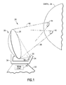
- Figure 1 shows a communication system 20 having a satellite 22 which encircles the earth 24.
- the satellite 22 carries an antenna 26 constructed in accordance with the invention and having a reflector 28 illuminated by a primary feed 30 and a secondary feed 32.
- the feeds 30 and 32 constitute a feed assembly 34 which is positioned by a frame 36 relative to the reflector 28.
- the primary feed 30 transmits radiation to the reflector 28 which reflects the radiation to form a primary beam 38 which illuminates a portion of the earth as shown by a primary beam footprint 40.
- a secondary feed 32 transmits radiation to the reflector 28 which reflects the radiation to form a secondary beam 42 which illuminates a separate portion of the earth indicated by a secondary beam footprint 44.
- Figure 2 shows a system of coordinate axes of azimuth and elevation superposed upon a circle 46 (partially shown) which represents the projection of angles to the earth upon the feed assembly 34.
- the intersection of zero degrees in azimuth and zero degrees in elevation represents the centre 46A of the circle 46.
- the primary feed 30 is shown in Fig. 2, and is represented by a rectangular radiating aperture identified as Beam 1.
- the secondary feed 32 has a complex shape comprising, by way of example, eight feed elements 52, further identified by the numerals 1-8, and collectively identified as Beam 2.
- the centre of the array of feed elements 52 is displaced from the centre of the primary feed 30.
- the feed elements 52 of the secondary feed 32 radiate an electromagnetic signal provided by a transmitter 54 connected to individual ones of the feed elements 52 by a beam controller 56, also shown in Figure 1. Only three of the radiating elements 52 are shown in Figure 3 to simplify the drawing.
- the beam controller 56 comprises a power divider 58 which divides the power of the transmitter 54 among respective signal channels for respective ones of the feed elements 52, wherein each signal channel comprises an amplifier 60 and a phase shifter 62.
- Each of the amplifiers 60 has a gain which is preset, and each of the phase shifters 62 is preset to a specific amount of phase shift to provide the desired configuration to the secondary beam.
- the description of the beam controller 56 and the transmitter 54 is provided for the situation wherein the secondary feed 32 is transmitting radiant energy for the formation of a beam by the reflector 28 ( Figure 1).
- the teachings of the invention apply also to the case wherein the secondary feed 32 is receiving a signal via the secondary beam 42 ( Figure 1) in which case the beam controller 56 would include a power combiner (not shown) coupled to a receiver (not shown).
- each of the signal channels of the respective feed elements 52 would include a phase shifter, such as the phase shifter 62, and an amplifier including an adjustable attenuator (not shown).
- the signal amplitudes and phases are adjustable electronically by signals stored in a memory.
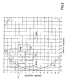
- Figure 4 shows an antenna radiation pattern 66, presented in solid lines, of the primary beam 38 (Figure 1) produced by radiation of the primary feed 30.
- Fig. 4 also shows an antenna radiation pattern 68, presented in dashed lines, of the secondary beam 42 ( Figure 1) provided by radiation from the secondary feed 32.
- the radiation pattern 66 has a main lobe 66A and a plurality of sidelobes 66B.
- the radiation pattern 68 also has a main beam 68A and a plurality of sidelobes 68B.
- the invention provides for a configuring of the radiation patterns 66 and 68 such that the sidelobes of one of the patterns 66 and 68 do not interfere with the main lobes of the other of the radiation patterns 66 and 68.
- the generation of the primary beam 38 and the secondary beam 42 are shown also in the diagram of Figure 5 wherein the components of the antenna 26 ( Figure 1) are shown diagrammatically superposed upon a system of coordinate axes X, Y and Z.
- the shaping of the reflector 28 to provide a specific configuration of beam is represented by a wavy line.
- the offsetting of the feed 30 and the feed elements 52 of the feed 32 is indicated also with reference to the X, Y, Z coordinate axes. To simplify the drawing, only three of the feed elements 52 of the secondary feed 32 are shown.
- the centre of the secondary feed 32 is offset from the centre of the feed 30 resulting in angulation of the primary beam 38 relative to the secondary beam 42.
- the angulation of the primary beam 38 relative to the secondary beam 42 is selected in accordance with the mission of the satellite 22 ( Figure 1) for illuminating the spaced apart regions of the earth, as represented by the footprints 40 and 44.
- the configuration of the reflector 28, the configuration of the array of the feed elements 52 of the secondary feed 32, the relative amplitudes of the signals of the respective feed elements 52, and the relative phases among the signals of the respective feed elements 52 establish the relationship among the lobes of the radiation patterns 66 and 68 of the primary beam 30 and the secondary beam 32 wherein, as noted hereinabove, the sidelobes of one of the radiation patterns does not interfere with the other of the radiation patterns.
- a diameter of the radiating aperture of the reflector 28 is on the order of 50 to 100 times as great as the diameter of the radiating aperture of the primary feed 30.
- a larger radiating aperture decreases angular spacing among the sidelobes 66B and a smaller radiating aperture enlarges the angular spacing among the sidelobes 66B.
- the angular spacing among the sidelobes 66B of the primary radiation pattern 66 are selected to provide for essentially zero radiation in the direction of the main lobe 68A of the secondary radiation pattern 68 by appropriate shaping of the surface contour of the reflector.
- the spacings of the feed elements 52 relative to each other, the amplitudes of the respective signals radiated by the feed elements 52, and the phasing among the signals of the respective feed elements 52 are selected to adjust the angular spacing among the sidelobes 68B of the secondary radiation pattern 68 to insure that there is essentially no sidelobe radiation from any of the sidelobes 68B in the direction of the main lobe 66A of the primary radiation pattern 66.
- spacings between neighbouring ones of the feed elements 52 are in the range of 0.5 to 5.0 wavelengths of the radiation emitted by the respective feed elements 52.
- the invention has provided for the generation of separate beams by use of separate feeds with a common reflector. This is accomplished by development of radiation patterns of interlaced lobe structure such that a lobe of one radiation pattern does not interfere with the radiation from the main lobe of the other radiation pattern. Since the reflector of the antenna has been configured to optimize efficiency of only one of the feeds, this being the primary feed 30, the foregoing advantage of improved isolation among the beams is attained at a cost of reduced efficiency of transmission of the signal of the secondary feed 32.
Abstract

Description
- This invention relates to an antenna having a reflector and a primary feed illuminating the reflector, the reflector serving to establish a cross-sectional configuration of a primary beam, wherein the antenna includes a secondary feed comprising an array of feed elements illuminating the reflector to produce a secondary beam with control of sidelobes away from a direction of the primary beam.
- An antenna constructed of a reflector illuminated by a feed may be employed in a situation wherein the antenna is required to generate plural beams of electromagnetic radiation. By way of example, in a satellite communication system, a satellite carrying such an antenna encircles the earth in a stationary orbit. The antenna produces the plural beams for simultaneous illumination of plural regions of the earth. Each of the beams has a prescribed cross-sectional configuration for producing a desired footprint at each of the respective illuminated regions of the earth.
- A feature in the construction of an antenna comprising a reflector illuminated by a feed is the shaping of the reflector for configuring the rays of radiation from the feed into a beam of desired cross-sectional configuration. This provides optimum efficiency in the transference of electromagnetic power from the feed to the illuminated region.
- To develop a second beam angled in direction relative to the primary beam of the primary feed, a secondary feed is positioned for illuminating the reflector, the two feeds being spaced apart so as to introduce the angulation between the two beams. Since the reflector has been configured for optimizing efficiency of the primary feed, the efficiency of transmission of radiant energy from the secondary feed occurs at a lower efficiency. Nevertheless, such an antenna is able to illuminate two separate regions of the earth's surface by the two beams.
- However, a problem arises in that the beams may have sidelobes in their respective radiation patterns with the result that a sidelobe of the primary beam may interfere with the propagation of signals from the main lobe of the secondary beam. Similarly, a sidelobe of the secondary beam may be oriented in the direction of the main lobe of the primary beam so as to interfere with the transmission of signals by the primary beam. It is, therefore, desirable to construct the antenna in a manner which avoids interference of the sidelobe of one beam within the main lobe of the other beam. However, a construction of antenna which introduces sufficient isolation of the plural beams has not been available heretofore, and separate antennas have been required for the generation of the separate beams.
- The invention seeks to reduce or overcome the problem previously mentioned and may provide other advantages. A construction in accordance with the invention, has an antenna which includes a reflector illuminated by both a primary feed and a secondary feed for generating plural beams while maintaining isolation between the respective beams.
- According to one aspect of the invention there is provided an antenna system, comprising a reflector and a primary feed positioned for illuminating the reflector to produce a primary beam, secondary feed positioned for illuminating the reflector to produce a secondary beam angled relative to the primary beam, wherein the secondary feed comprises an array of secondary feed elements positioned relative to each other with predetermined values of spacing for establishing directions of sidelobes of the secondary beam, a surface of the reflector is contoured for radiation of primary beam power at an efficiency of radiation greater than an efficiency of radiation of secondary beam power, a shape of the reflector offsetting directions of primary-beam sidelobes from a direction of radiation of the secondary beam, and the system further comprises means for establishing relative phases and amplitudes among signals of respective ones of the secondary feed elements for adjustment of the sidelobes to offset each of the sidelobes away from a direction of the primary beam.
- According to another aspect of the invention there is provided a method of modifying an antenna having a reflector illuminated by a primary feed to accept a secondary feed for generation of both primary and secondary beams angled relative to each other, the method comprising steps of constructing the secondary feed of an array of feed elements, locating the secondary feed relative to the reflector for illuminating the reflector, said locating including an offsetting of a position of the secondary feed relative to the primary feed and establishing values of spacing among the feed elements of the secondary feed, values of phasing of signals among the feed elements of the secondary feed, and values of amplitude of the signals among the feed elements of the secondary feed to establish a radiation pattern of the secondary beam having all lobes offset from a main lobe of the primary beam.
- The invention provides for a reflector and a primary feed positioned for illuminating the reflector, wherein the reflector is configured for reflecting the radiation of the primary feed to form a beam of desired cross section. This optimizes efficiency of transmission of the electromagnetic power in the sense that virtually all of the power radiated by the primary feed is captured within the footprint. Typically, the primary feed comprises a single radiating element, such as a horn, but may, if desired, comprise a plurality of radiating elements, such as a cluster of four horns. The antenna of the invention includes also a secondary feed which is offset in position from the primary feed, and which also illuminates the reflector for generation of a secondary beam produced by the reflector. The secondary beam is oriented in a direction angled relative to the direction of the primary beam. The secondary beam is less efficient in the transmission of radiant energy from the secondary feed due to the fact that the reflector has been shaped specifically for coverage by the primary beam.
- In the construction of the antenna, it is recognized that sidelobes of the primary beam are dependent on the cross-sectional configuration of the reflector and the surface contour of the reflector. By way of example in a typical construction of the antenna, a diameter of the radiating aperture of the reflector is on the order of 50 to 100 times as great as the diameter of the radiating aperture of the primary feed. By increasing the diameter of the radiating aperture of the reflector, the sidelobes of the primary beam can be brought closer, in terms of angulation, to the main lobe of the primary beam. In order to minimize interference with transmissions of the secondary beam, the reflector is shaped to suppress primary-beam sidelobes in the secondary-beam direction. Furthermore, the reflector is specifically shaped with a surface contour which directs lobes of the primary beam in directions away from the axis of the secondary beam.
- The secondary feed may be constructed of an array of feed elements which results in the generation, in cooperation with the reflector, of the secondary beam which comprises both a main lobe and sidelobes. The configuration of the reflector has already been established for optimizing the configuration of the primary beam. Accordingly, optimization of the configuration of the secondary beam may be accomplished by a selection of spacings among the feed elements in the array, by use of a phase taper to signals transmitted by the respective feed elements of the array, and by adjustment of the relative amplitudes of the signals transmitted by the respective elements of the array. The parameters of spacing, phasing and amplitude are employed to configure the secondary beam by adjustment of the orientations of the sidelobes relative to the main lobe. In particular, the sidelobes are positioned such that there is essentially no sidelobe radiation being transmitted in the direction of the main lobe of the primary beam. Thereby, the invention has attained the desired isolation between signals transmitted via the main lobes of the primary and the secondary beams.
- In order that the invention and its various other preferred features may be understood more easily, some embodiments thereof will now be described, by way of example only, with reference to the drawings, in which,
- Figure 1 is a stylized view of a satellite carrying an antenna constructed in accordance with the invention while circling the earth,
- Figure 2 is a diagram showing an arrangement of feed elements in a feed assembly of the antenna of Figure 1,
- Figure 3 is a block diagram showing components of a beam controller for the antenna of Figure 1,
- Figure 4 shows radiation patterns of a primary beam and a secondary beam for the antenna of Figure 1 and
- Figure 5 shows diagrammatically the relative orientations of the primary beam and the secondary beam produced, respectively, by a primary feed and an array of secondary feed elements in the antenna of Figure 1.
-
- Identically labelled elements appearing in different ones of the figures refer to the same element but may not be referenced in the description for all figures.
- Figure 1 shows a
communication system 20 having asatellite 22 which encircles theearth 24. Thesatellite 22 carries anantenna 26 constructed in accordance with the invention and having areflector 28 illuminated by aprimary feed 30 and asecondary feed 32. Thefeeds feed assembly 34 which is positioned by aframe 36 relative to thereflector 28. Theprimary feed 30 transmits radiation to thereflector 28 which reflects the radiation to form aprimary beam 38 which illuminates a portion of the earth as shown by aprimary beam footprint 40. Asecondary feed 32 transmits radiation to thereflector 28 which reflects the radiation to form asecondary beam 42 which illuminates a separate portion of the earth indicated by asecondary beam footprint 44. - Figure 2 shows a system of coordinate axes of azimuth and elevation superposed upon a circle 46 (partially shown) which represents the projection of angles to the earth upon the
feed assembly 34. The intersection of zero degrees in azimuth and zero degrees in elevation represents the centre 46A of thecircle 46. Theprimary feed 30 is shown in Fig. 2, and is represented by a rectangular radiating aperture identified as Beam 1. Thesecondary feed 32 has a complex shape comprising, by way of example, eightfeed elements 52, further identified by the numerals 1-8, and collectively identified as Beam 2. The centre of the array offeed elements 52 is displaced from the centre of theprimary feed 30. - In Figure 3, the
feed elements 52 of thesecondary feed 32 radiate an electromagnetic signal provided by atransmitter 54 connected to individual ones of thefeed elements 52 by abeam controller 56, also shown in Figure 1. Only three of theradiating elements 52 are shown in Figure 3 to simplify the drawing. Thebeam controller 56 comprises apower divider 58 which divides the power of thetransmitter 54 among respective signal channels for respective ones of thefeed elements 52, wherein each signal channel comprises anamplifier 60 and aphase shifter 62. Each of theamplifiers 60 has a gain which is preset, and each of thephase shifters 62 is preset to a specific amount of phase shift to provide the desired configuration to the secondary beam. - It is noted that the description of the
beam controller 56 and thetransmitter 54 is provided for the situation wherein thesecondary feed 32 is transmitting radiant energy for the formation of a beam by the reflector 28 (Figure 1). However, it is to be understood that the teachings of the invention apply also to the case wherein thesecondary feed 32 is receiving a signal via the secondary beam 42 (Figure 1) in which case thebeam controller 56 would include a power combiner (not shown) coupled to a receiver (not shown). In the case of the receiving of signals, each of the signal channels of therespective feed elements 52 would include a phase shifter, such as thephase shifter 62, and an amplifier including an adjustable attenuator (not shown). For the receiving of signals, the signal amplitudes and phases are adjustable electronically by signals stored in a memory. - Figure 4 shows an
antenna radiation pattern 66, presented in solid lines, of the primary beam 38 (Figure 1) produced by radiation of theprimary feed 30. Fig. 4 also shows anantenna radiation pattern 68, presented in dashed lines, of the secondary beam 42 (Figure 1) provided by radiation from thesecondary feed 32. Theradiation pattern 66 has amain lobe 66A and a plurality ofsidelobes 66B. Theradiation pattern 68 also has amain beam 68A and a plurality ofsidelobes 68B. The invention provides for a configuring of theradiation patterns patterns radiation patterns - The generation of the
primary beam 38 and thesecondary beam 42 are shown also in the diagram of Figure 5 wherein the components of the antenna 26 (Figure 1) are shown diagrammatically superposed upon a system of coordinate axes X, Y and Z. The shaping of thereflector 28 to provide a specific configuration of beam is represented by a wavy line. The offsetting of thefeed 30 and thefeed elements 52 of thefeed 32 is indicated also with reference to the X, Y, Z coordinate axes. To simplify the drawing, only three of thefeed elements 52 of thesecondary feed 32 are shown. The centre of thesecondary feed 32 is offset from the centre of thefeed 30 resulting in angulation of theprimary beam 38 relative to thesecondary beam 42. - In the operation of the invention, the angulation of the
primary beam 38 relative to thesecondary beam 42 is selected in accordance with the mission of the satellite 22 (Figure 1) for illuminating the spaced apart regions of the earth, as represented by thefootprints reflector 28, the configuration of the array of thefeed elements 52 of thesecondary feed 32, the relative amplitudes of the signals of therespective feed elements 52, and the relative phases among the signals of therespective feed elements 52 establish the relationship among the lobes of theradiation patterns primary beam 30 and thesecondary beam 32 wherein, as noted hereinabove, the sidelobes of one of the radiation patterns does not interfere with the other of the radiation patterns. - In the case wherein the
primary feed 30 has only one feed element, as has been depicted in Figures 2 and 5, adjustment of the lobe structure of theprimary radiation pattern 66 is obtained by selection of the cross-sectional and surface shaping dimensions of the radiating aperture of thereflector 28. Typically, in the construction of the antenna, a diameter of the radiating aperture of thereflector 28, by way of example, is on the order of 50 to 100 times as great as the diameter of the radiating aperture of theprimary feed 30. A larger radiating aperture decreases angular spacing among thesidelobes 66B and a smaller radiating aperture enlarges the angular spacing among thesidelobes 66B. In particular, the angular spacing among the sidelobes 66B of theprimary radiation pattern 66 are selected to provide for essentially zero radiation in the direction of themain lobe 68A of thesecondary radiation pattern 68 by appropriate shaping of the surface contour of the reflector. - Furthermore, in the
secondary feed 32, the spacings of thefeed elements 52 relative to each other, the amplitudes of the respective signals radiated by thefeed elements 52, and the phasing among the signals of therespective feed elements 52 are selected to adjust the angular spacing among the sidelobes 68B of thesecondary radiation pattern 68 to insure that there is essentially no sidelobe radiation from any of thesidelobes 68B in the direction of themain lobe 66A of theprimary radiation pattern 66. In the construction of thesecondary feed 32, typically, spacings between neighbouring ones of thefeed elements 52 are in the range of 0.5 to 5.0 wavelengths of the radiation emitted by therespective feed elements 52. The foregoing control of the relative angular locations of the respective sidelobes of theradiation pattern feeds - In this way, the invention has provided for the generation of separate beams by use of separate feeds with a common reflector. This is accomplished by development of radiation patterns of interlaced lobe structure such that a lobe of one radiation pattern does not interfere with the radiation from the main lobe of the other radiation pattern. Since the reflector of the antenna has been configured to optimize efficiency of only one of the feeds, this being the
primary feed 30, the foregoing advantage of improved isolation among the beams is attained at a cost of reduced efficiency of transmission of the signal of thesecondary feed 32.
Claims (6)
- An antenna system, comprising a reflector (28) and a primary feed (30) positioned for illuminating the reflector to produce a primary beam (38), secondary feed (32) positioned for illuminating the reflector (28) to produce a secondary beam (42) angled relative to the primary beam, wherein the secondary feed (32) comprises an array of secondary feed elements (52) positioned relative to each other with predetermined values of spacing for establishing directions of sidelobes (68B) of the secondary beam (42), a surface of the reflector (28) is contoured for radiation of primary beam power at an efficiency of radiation greater than an efficiency of radiation of secondary beam power, a shape of the reflector offsetting directions of primary-beam sidelobes (66B) from a direction of radiation of the secondary beam (42), and the system further comprises means (56) for establishing relative phases and amplitudes among signals of respective ones of the secondary feed elements (52) for adjustment of the sidelobes (68B) to offset each of the sidelobes away from a direction of the primary beam.
- A system as claimed in Claim 1, wherein the predetermined values of spacing are in a range of approximately 0.5 wavelengths to 5.0 wavelengths of radiation emanating from the secondary feed.
- A system as claimed in Claim 2, wherein the diameter of the reflector (28) exceeds a diameter of the array of secondary feed elements (52) by a factor in a range of approximately 50 to 100.
- A system as claimed in Claim 3, wherein the factor effects an orientation of a sidelobe (66B) of the primary beam (38) relative to a main lobe (66A) of the primary beam (38), the factor having a value for offsetting the sidelobes (66B) of the primary beam (38) relative to a direction of the secondary beam (42).
- A system as claimed in any one of the preceding claims, wherein the contour of the surface of the reflector (28) provides for a maximum efficiency of radiation of the primary beam (38).
- A method of modifying an antenna having a reflector illuminated by a primary feed to accept a secondary feed for generation of both primary and secondary beams angled relative to each other, the method comprising steps of constructing the secondary feed of an array of feed elements, locating the secondary feed relative to the reflector for illuminating the reflector, said locating including an offsetting of a position of the secondary feed relative to the primary feed and establishing values of spacing among the feed elements of the secondary feed, values of phasing of signals among the feed elements of the secondary feed, and values of amplitude of the signals among the feed elements of the secondary feed to establish a radiation pattern of the secondary beam having all lobes offset from a main lobe of the primary beam.
Applications Claiming Priority (2)
| Application Number | Priority Date | Filing Date | Title |
|---|---|---|---|
| US08/961,169 US6137451A (en) | 1997-10-30 | 1997-10-30 | Multiple beam by shaped reflector antenna |
| US961169 | 1997-10-30 |
Publications (2)
| Publication Number | Publication Date |
|---|---|
| EP0920076A2 true EP0920076A2 (en) | 1999-06-02 |
| EP0920076A3 EP0920076A3 (en) | 2000-08-23 |
Family
ID=25504158
Family Applications (1)
| Application Number | Title | Priority Date | Filing Date |
|---|---|---|---|
| EP98308731A Withdrawn EP0920076A3 (en) | 1997-10-30 | 1998-10-26 | Multiple beam by shaped reflector antenna |
Country Status (4)
| Country | Link |
|---|---|
| US (1) | US6137451A (en) |
| EP (1) | EP0920076A3 (en) |
| JP (1) | JPH11225018A (en) |
| CA (1) | CA2247700A1 (en) |
Cited By (3)
| Publication number | Priority date | Publication date | Assignee | Title |
|---|---|---|---|---|
| EP1085598A2 (en) * | 1999-09-20 | 2001-03-21 | EADS Deutschland Gmbh | Reflector with shaped surface and spatial separated foci for the illumination of identical areas, antenna system and method for determining the surface |
| EP1107359A1 (en) * | 1999-12-09 | 2001-06-13 | Alcatel | Radiating source for an antenna to be installed in a satellite |
| WO2003081717A1 (en) * | 2002-03-21 | 2003-10-02 | Kathrein-Werke Kg | Method and device for tracking an antenna |
Families Citing this family (11)
| Publication number | Priority date | Publication date | Assignee | Title |
|---|---|---|---|---|
| US7369847B1 (en) * | 2000-09-14 | 2008-05-06 | The Directv Group, Inc. | Fixed cell communication system with reduced interference |
| US7038632B2 (en) * | 2001-09-14 | 2006-05-02 | Andrew Corporation | Co-located multi-band antenna |
| US6570528B1 (en) * | 2001-11-09 | 2003-05-27 | The Boeing Company | Antenna system for multiple orbits and multiple areas |
| US7856243B2 (en) * | 2007-12-05 | 2010-12-21 | Telefonaktiebolaget Lm Ericsson | Power control for a radio transceiver that uses interference cancellation |
| JP5317821B2 (en) * | 2009-05-13 | 2013-10-16 | 三菱電機株式会社 | Antenna device |
| US20110032143A1 (en) * | 2009-08-05 | 2011-02-10 | Yulan Sun | Fixed User Terminal for Inclined Orbit Satellite Operation |
| JP5659905B2 (en) * | 2011-03-29 | 2015-01-28 | 日本電気株式会社 | Microwave transmission apparatus for satellite installation, target area tracking method using the apparatus, and control program |
| JP2014017708A (en) * | 2012-07-10 | 2014-01-30 | Nippon Hoso Kyokai <Nhk> | Space synthesis antenna device and manufacturing method for modified mirror surface reflector |
| FR3026896B1 (en) * | 2014-10-03 | 2018-07-06 | Thales | REFLECTING ANTENNA (S) CONFORMING (S) RECONFIGURABLE IN ORBIT |
| US10122085B2 (en) | 2014-12-15 | 2018-11-06 | The Boeing Company | Feed re-pointing technique for multiple shaped beams reflector antennas |
| US9893417B2 (en) * | 2015-01-29 | 2018-02-13 | Speedcast International Limited | Satellite communications terminal for a ship and associated methods |
Citations (5)
| Publication number | Priority date | Publication date | Assignee | Title |
|---|---|---|---|---|
| US3936835A (en) * | 1974-03-26 | 1976-02-03 | Harris-Intertype Corporation | Directive disk feed system |
| DE2752680A1 (en) * | 1977-11-25 | 1979-05-31 | Siemens Ag | Directional aerial for very short waves - has main exciter producing main lobe, and secondary exciters producing secondary lobes compensating interferences |
| EP0467738A1 (en) * | 1990-07-20 | 1992-01-22 | Thomson-Csf | Azimuth angle measuring device for a radar provided with a double curvature reflective-type antenna |
| FR2674377A1 (en) * | 1991-03-22 | 1992-09-25 | Alcatel Espace | Radio frequency antenna with multi-focal reflector |
| GB2262387A (en) * | 1991-12-09 | 1993-06-16 | Alcatel Espace | Multibeam antenna |
Family Cites Families (9)
| Publication number | Priority date | Publication date | Assignee | Title |
|---|---|---|---|---|
| US3435453A (en) * | 1967-11-06 | 1969-03-25 | Us Navy | Sidelobe cancelling system for array type target detectors |
| US3569976A (en) * | 1968-08-29 | 1971-03-09 | William Korvin | Antenna array at focal plane of reflector with coupling network for beam switching |
| US3534365A (en) * | 1969-05-01 | 1970-10-13 | Nasa | Tracking antenna system |
| US3898667A (en) * | 1974-02-06 | 1975-08-05 | Rca Corp | Compact frequency reuse antenna |
| US4647938A (en) * | 1984-10-29 | 1987-03-03 | Agence Spatiale Europeenne | Double grid reflector antenna |
| US5202700A (en) * | 1988-11-03 | 1993-04-13 | Westinghouse Electric Corp. | Array fed reflector antenna for transmitting & receiving multiple beams |
| GB2264006B (en) * | 1992-02-01 | 1995-09-27 | British Aerospace Space And Co | A reflector antenna assembly for dual linear polarisation |
| US5546097A (en) * | 1992-12-22 | 1996-08-13 | Hughes Aircraft Company | Shaped dual reflector antenna system for generating a plurality of beam coverages |
| US5576721A (en) * | 1993-03-31 | 1996-11-19 | Space Systems/Loral, Inc. | Composite multi-beam and shaped beam antenna system |
-
1997
- 1997-10-30 US US08/961,169 patent/US6137451A/en not_active Expired - Lifetime
-
1998
- 1998-09-22 CA CA002247700A patent/CA2247700A1/en not_active Abandoned
- 1998-10-21 JP JP10299263A patent/JPH11225018A/en active Pending
- 1998-10-26 EP EP98308731A patent/EP0920076A3/en not_active Withdrawn
Patent Citations (5)
| Publication number | Priority date | Publication date | Assignee | Title |
|---|---|---|---|---|
| US3936835A (en) * | 1974-03-26 | 1976-02-03 | Harris-Intertype Corporation | Directive disk feed system |
| DE2752680A1 (en) * | 1977-11-25 | 1979-05-31 | Siemens Ag | Directional aerial for very short waves - has main exciter producing main lobe, and secondary exciters producing secondary lobes compensating interferences |
| EP0467738A1 (en) * | 1990-07-20 | 1992-01-22 | Thomson-Csf | Azimuth angle measuring device for a radar provided with a double curvature reflective-type antenna |
| FR2674377A1 (en) * | 1991-03-22 | 1992-09-25 | Alcatel Espace | Radio frequency antenna with multi-focal reflector |
| GB2262387A (en) * | 1991-12-09 | 1993-06-16 | Alcatel Espace | Multibeam antenna |
Cited By (7)
| Publication number | Priority date | Publication date | Assignee | Title |
|---|---|---|---|---|
| EP1085598A2 (en) * | 1999-09-20 | 2001-03-21 | EADS Deutschland Gmbh | Reflector with shaped surface and spatial separated foci for the illumination of identical areas, antenna system and method for determining the surface |
| DE19945062A1 (en) * | 1999-09-20 | 2001-04-12 | Daimler Chrysler Ag | Reflector with a shaped surface and spatially separated foci for illuminating identical areas, antenna system and method for determining the surface |
| JP2001127538A (en) * | 1999-09-20 | 2001-05-11 | Daimlerchrysler Ag | Reflecting mirror for antenna, antenna system using the reflecting mirror, and method for deciding surface shape of the reflecting mirror |
| US6255997B1 (en) | 1999-09-20 | 2001-07-03 | Daimlerchrysler Ag | Antenna reflector having a configured surface with separated focuses for covering identical surface areas and method for ascertaining the configured surface |
| EP1085598A3 (en) * | 1999-09-20 | 2002-07-31 | EADS Deutschland Gmbh | Reflector with shaped surface and spatial separated foci for the illumination of identical areas, antenna system and method for determining the surface |
| EP1107359A1 (en) * | 1999-12-09 | 2001-06-13 | Alcatel | Radiating source for an antenna to be installed in a satellite |
| WO2003081717A1 (en) * | 2002-03-21 | 2003-10-02 | Kathrein-Werke Kg | Method and device for tracking an antenna |
Also Published As
| Publication number | Publication date |
|---|---|
| EP0920076A3 (en) | 2000-08-23 |
| JPH11225018A (en) | 1999-08-17 |
| US6137451A (en) | 2000-10-24 |
| CA2247700A1 (en) | 1999-04-30 |
Similar Documents
| Publication | Publication Date | Title |
|---|---|---|
| US5949370A (en) | Positionable satellite antenna with reconfigurable beam | |
| US6366256B1 (en) | Multi-beam reflector antenna system with a simple beamforming network | |
| US6094166A (en) | Conical omni-directional coverage multibeam antenna with parasitic elements | |
| US5872547A (en) | Conical omni-directional coverage multibeam antenna with parasitic elements | |
| US6456252B1 (en) | Phase-only reconfigurable multi-feed reflector antenna for shaped beams | |
| US6268828B1 (en) | Cylindrical antenna coherent feed system and method | |
| EP0845833B1 (en) | On-orbit reconfigurability of a shaped reflector with feed/reflector defocusing and reflector gimballing | |
| US6137451A (en) | Multiple beam by shaped reflector antenna | |
| US6011512A (en) | Thinned multiple beam phased array antenna | |
| EP0466126B1 (en) | Method and apparatus for producing multiple, frequency-addressable scanning beams | |
| US6172654B1 (en) | Conical omni-directional coverage multibeam antenna | |
| EP1020952A1 (en) | Gregorian antenna system | |
| US7242904B2 (en) | Dual-band multiple beam antenna system for communication satellites | |
| US6392611B1 (en) | Array fed multiple beam array reflector antenna systems and method | |
| EP1289059A3 (en) | Dual-band reflector antenna using dual-band feed horns and equal up-link and down-link beamwidths | |
| EP1076377B1 (en) | Satellite antenna pointing system | |
| US6215452B1 (en) | Compact front-fed dual reflector antenna system for providing adjacent, high gain antenna beams | |
| JP2021524723A (en) | Array fed reflector antenna | |
| JPH06318817A (en) | Molded double reflector antenna system for generating a plurality of beam-covered range | |
| US6211835B1 (en) | Compact side-fed dual reflector antenna system for providing adjacent, high gain antenna beams | |
| US6504516B1 (en) | Hexagonal array antenna for limited scan spatial applications | |
| CA2293506C (en) | A compact folded optics antenna system for providing adjacent, high gain antenna beams | |
| US6424312B2 (en) | Radiating source for a transmit and receive antenna intended to be installed on board a satellite | |
| JPH0515081B2 (en) | ||
| JPH0295003A (en) | Scanning antenna |
Legal Events
| Date | Code | Title | Description |
|---|---|---|---|
| PUAI | Public reference made under article 153(3) epc to a published international application that has entered the european phase |
Free format text: ORIGINAL CODE: 0009012 |
|
| AK | Designated contracting states |
Kind code of ref document: A2 Designated state(s): DE FR GB IT |
|
| AX | Request for extension of the european patent |
Free format text: AL;LT;LV;MK;RO;SI |
|
| PUAL | Search report despatched |
Free format text: ORIGINAL CODE: 0009013 |
|
| AK | Designated contracting states |
Kind code of ref document: A3 Designated state(s): AT BE CH CY DE DK ES FI FR GB GR IE IT LI LU MC NL PT SE |
|
| AX | Request for extension of the european patent |
Free format text: AL;LT;LV;MK;RO;SI |
|
| 17P | Request for examination filed |
Effective date: 20001108 |
|
| AKX | Designation fees paid |
Free format text: DE FR GB IT |
|
| STAA | Information on the status of an ep patent application or granted ep patent |
Free format text: STATUS: THE APPLICATION HAS BEEN WITHDRAWN |
|
| 18W | Application withdrawn |
Effective date: 20030710 |